SlideShare a Scribd company logo
1 of 25
Download to read offline
郭珂/Guoke +86 132 9904 2234 Skype: guoke896884090
Page 1 of 25
guoke1207@hotmail.com
5T
INTERMEDIATE FREQUENCY WITHOUT CORE INDUCTION
MELT COOKER TECHNOLOGY SCHEME
Summarize:
In this scheme, a set of equipment consist of two electric cooker
bodies, an intermediate frequency electrical source, a hydraulic pressure
equipment. A intermediate frequency electrical source supplies powers
for two electric cookers in which one are melting ,the other are standby.
Ⅰ. Technique parameter
item Unit data
Electric cookers parameter
Rating capacity t 5
Maximum capacity t 6
maximum working temperature ℃ 1750
electric parameter
transformer capacity KVA 3500
transformer first voltage KV 10
transformer second voltage V 750、750
intermediate frequency
electrical source
rating power
KW 3000
intermediate frequency
electrical source maximum
output voltage
V 1500
working frequency Hz 250
transforming frequency % 98
start-up success frequency % 100
complex parameter
fusion ratio(temperature
was raised to 1600 ℃)
t/h 4.8
power cost of fusion
(temperature was raised
KW·h/t 600
郭珂/Guoke +86 132 9904 2234 Skype: guoke896884090
Page 2 of 25
guoke1207@hotmail.com
to 1600 ℃)
working noises db =85
hydraulic pressure system
station capacity L 500
working pressure Mpa 13
hydraulic pressure medium grease
cooling water system
flow quantity t/h 144
water supply pressure Mpa 0.25-0.35
input water temperature ℃ 5-35
output water temperature ℃ <55
Ⅱ. Technical criterion and working condition of equipment
The parts of the equipment accord corresponding technical criterion listed
behind.
1. GBl0067.3— 88 the basic technical condition of
galvanothermy equipment— induction galvanothermy equipment.
2. GBl0063.3— 88 the experiment method of galvanothermy
equipment— non-core induction melting cooker.
3. GB5959.3-88 the safety of galvanothermy equipment— special
require on inductive and conductive heater and inductive melting
equipment.
4. JB4086-85 intermediate frequency non-core induction
heat-up use the technical condition of the equipments controlled by
electricity.
5. JB / T4280— 93 intermediate frequency non-core induction
cooker.
6. GB/T14549-93 the quality of power— the performance and
郭珂/Guoke +86 132 9904 2234 Skype: guoke896884090
Page 3 of 25
guoke1207@hotmail.com
technical parameter of the resonance-wave equipment used in electricity
network reach the regulation of technology specification book.
Ⅲ. Normal working condition of the equipment listing behind
1. Environment
a. Altitude is below 1000 m.
b. Surroundings temperature is between 5 ℃ and 40℃.
c. Relative humidity is not above 90% (25℃).
d. No conductive dust, explosive gas and causticity gas which can
damage metal and insulation.
e. No obvious vibration and jounce.
2. Power supply demand
a. Power supply voltage in main circuit is 1OKV, fluctuation is less
5% and three phase imbalance is less 5%.
b. Power supply voltage in control system is 220 V and fluctuation is
less 5%.
c. Power supply voltage in main circuit and control system must be
sine wave whose shape aberration is less 10%.
3. The demand of cooling water in outside cycle
a. Overall rigidity is less 60 mg equal quantity per liter.
b. dissolutive solid substance < 300 mg/L.
c. PH 7— 8.5.
d. suspension solid substance < lOmg/L.
郭珂/Guoke +86 132 9904 2234 Skype: guoke896884090
Page 4 of 25
guoke1207@hotmail.com
e. conductance rate <500µs/cm.
f. input water temperature =35℃.
Ⅳ. Technique explanation of electric parts
The electric parts of equipments consist of
electrical source commutation transformer,
Intermediate frequency electrical source cabinet,
compensation capacitor groups, and high voltage
switch cabinet.
1. Electrical source transformer
The electrical source transformer is used to
drop 11KV high voltage electricity in electric network to one which can
fit Intermediate frequency electrical source. The equipment adopts special
commutation transformers which self-cooling dipped in oil.
1.1 commutation transformer used for fusion:
rating capacity 3500 KVA
the first voltage 10 KV,
the second voltage 750 V。
impedance in short circuit between 6% and 8%
non-load switch installed on the high voltage side and used to
regulate voltage by hand can adjust on three stages -5%,0,+5%.
郭珂/Guoke +86 132 9904 2234 Skype: guoke896884090
Page 5 of 25
guoke1207@hotmail.com
1.2. Intermediate frequency
electrical source
The type of intermediate
frequency electrical source in the
electric cooker is KGPS -3000
/0.25.
Circuit principle drawing is listed
below.
2. Intermediate frequency electrical source main loop principle chart
2.1 Commutate part control silicon adopt up to date fold installed
radiator groupware as following chart
This kind of install mode is more convenience and science to remove
and install control silicon .When change control silicon, only loosen tip
tighten bolt, you can change anyone control silicon component in
groupware. Radiator component has scale which can consult when fasten,
and this guarantee right pressure during control silicon and radiator.
Moreover, this kind of installs mode minish control silicon groupware
郭珂/Guoke +86 132 9904 2234 Skype: guoke896884090
Page 6 of 25
guoke1207@hotmail.com
volume, which makes operation room in electric cabinet bigger.
2.2 Great capacity direct current sieve wave reactor
Sieve wave reactor is very important for solid electrical source,it has
two function ,the one is to make output current smooth and stable;the
other is when athwart change control silicon short circuit,it circumscribe
short circuit increase rate and the biggest short circuit 。If sieve wave
reactor parameter design inconsequence,iron core material is not good or
production techniques do not pass the test ,all those may influence
reliability of intermediate frequency electrical source。
2.3 Athwart change circuit adopt great speediness control silicon
To guarantee athwart change circuit reliability,athwart change control
silicon adopt two big capacity KK silicon in series
2.4. Adopt series-parallel connection compensate circuitry to minish
wastage of transmit electricity circuitry
To minish intermediate frequency transmit electricity circuitry wastage,
athwart change circuit compensate capacitor adopt series-parallel
connection, as follows:
C1
L
Intermediate C2
Frequency output
This kind connection can enhance cooker output voltage twice as
郭珂/Guoke +86 132 9904 2234 Skype: guoke896884090
Page 7 of 25
guoke1207@hotmail.com
athwart change circuit. And at the same output power output electrical
current become only 50% as before, which make intermediate frequency
transmit circuitry wastage minish to 1/4.
2.5 Main circuit parameter and component selection foundation
When adopt 6 pulse wave rectifiers, commutate control silicon
average electrical current can be calculated according to the following
formula:
Ikpmax=Id max/2.72
Athwart change control silicon average electrical current can be calculate
according to the following formula:
Ikkmax=0.45XIdmax
Choose control silicon standard and select
2.6 Characteristic of intermediate frequency electrical source
2.6.1 Control system total numeric, without continue electricity control
Control system adopt ISP program logical array module to
integration control. Its core apparatus adopt high performance, high
density ,great standard special ASTC-2 integration circuit ,which is made
in USA, and this makes all signal
dispose and correspondence
operation carry out automatism
according to program. Replace all
kind of continue electricity control
郭珂/Guoke +86 132 9904 2234 Skype: guoke896884090
Page 8 of 25
guoke1207@hotmail.com
with data control system to finish the function.
2.6.2 Unique browse frequency model startup mode has 100% startup
succeed rate.
Athwart change part adopt browse frequency zero pressure soft
startup ,which has better performance than common zero pressure soft
startup circuit。Browse frequency model startup process as following:
before startup,touch off athwart change
crystal brake pipe with stimulating signal whose frequency is higher than
slot route syntony, moreover control stimulate signal frequency to
browse from high to low,when the frequency is near slot route syntony,
intermediate frequency voltage is set up .To prevent intermediate
frequency voltage startup failure occasionally,our company design
automatism startup circuit,ensure 100% startup succeed rate,moreover ,
its response time is very short,it only takes less than 500 MSEL to finish
a automatism startup.
2.6.3 Adjuster with quick respond identity
Our company have design particular adjuster in control circuitry
whose responding time is very short, the adjuster is completely fit for the
use demand of speediness respond in the condition of the load break of
intermediate power supply.
2.6.4 Electrical source constant power is output to ensure supernal power
郭珂/Guoke +86 132 9904 2234 Skype: guoke896884090
Page 9 of 25
guoke1207@hotmail.com
factor
The impedance adjuster is devised especially which can inspect the
change of the impedance and deliver it to circuit interior processing
figure operation and adjust automatically matching load to make
intermediate frequency power supply reach constant power. At the same
time, the running power factor of the whole set equipment reaches above
0.93 because of using impedance adjuster in the course of melting. The
relation graph of constant power intermediate frequency voltage US and
its corresponding power factor φcos is given in following drawing.
COS?
0
1050V 1300V
Us
(Constant power intermediate frequency voltage and its
corresponding power factor connection graph)
2.6.5 Having outstanding anti-striking load capacity
There leave enough space in choosing main apparatus in system.,
which guarantee each apparatus outstanding anti-striking capacity。Our
firm provides especial device in control part of system on software, and
郭珂/Guoke +86 132 9904 2234 Skype: guoke896884090
Page 10 of 25
guoke1207@hotmail.com
this makes system running more stationary and reliable and prevent
monocrystalline silicon efficiently from damage of electric impulse while
adding material .Thus, the equipment’s good capability of impulsion
resistance is ensured and the equipment can run on the safe side in long
period.
2.6.6 Perfect and reliable protection function
Such protection measure of overflow, overload, over press,phase
shortage, lack of voltage of controllable power, too low cooling water
pressure, too high temperature of cooling water and too low water flux
are provided in this controlling circuitry. These protection functions are
analyzed and realized by ASIC-2 integrate circuit, which ensures the
sensitivity and reliability of those protection function. This system is
water cooling equipment, real time inspection to cooling water on many
point has to be carried out for equipment runs on the safe side. Our firm
devises a set of characteristic inspect instrument for a special purpose aim
at importance of water inspection. Two temperature inspection points is
set on each controllable silicon, and the same points is set on each
syntonic capacitor and every induction loop. This makes each part of
water cooling of this system be inspected at real time. It is impossible to
damage part of apparatus which have too high water temperature on one
point.
2.6.7 Advanced auto identify function of phase order
郭珂/Guoke +86 132 9904 2234 Skype: guoke896884090
Page 11 of 25
guoke1207@hotmail.com
A auto identify circuit of phase order is contained in controllable
system, which makes system need not install synchronic transformation
and excuse phase order modulation and the job to synchronize while
debugging and maintaining.
2.6.8 abundant outside controllable interface
It is set on the equipment that Out/In transformation, Auto/Hand
control switch and their interface, which can realize auto controlment
from long distance conveniently. And outside temperature ring
controllable interface is set to combine infrared temperature inspect
instrument and temperature auto controlling system, which can realize the
auto modulation of program enactment temperature rising to output
power of electrical source and makes final calefaction temperature of
steel tube reach anticipated temperature.
2.6.9 Light isolation impulse output
In controlling system, there are double isolation measures in
springing impulse between controlling board to controlling pole of
controllable silicon. Light isolation apparatus with its pressure endurance
over 2500V is used on controlling board to insulate springing impulse
from light or electricity, and transformer groupware with its pressure
endurance grade of over 3000V is used on impulse transformer. Even
though controllable silicon is stroked out because of over pressure, it has
little influence on controlling system.
郭珂/Guoke +86 132 9904 2234 Skype: guoke896884090
Page 12 of 25
guoke1207@hotmail.com
2.6.10 Simple and convenient to debug and maintain
The major parameters’settings on controlling board are finished by
internal circuit of controlling board. There are only six potentiometer
parameters’settings which can be modulated by user. So the controlling
board is perfectly universal and reciprocates, and it is simple and
convenient to debug and maintain.
2.7 Cooker leaking protection and earthling alarm brake function
A special detector of cooker liner’s thickness is set on controlling
system. The working theory is to verdict the perfection of cooker liner
through leaking current between inductive loops and charging.
Because leaking current must amply while cooker liner becomes thin.
Alarm current of cooker liner thickness detector can be modulated.
Appropriate alarm current must be modulated gradually while it is being
used according to different size of cooker and different material of cooker
line.
Cooker liner thickness detector cann’t runs correctly 100 percent. It
can only offer reference of judging cooker liner thickness.
The cooker liner thickness detector is connected between side pole
and bottom pole directly.
2.8 Compensating capacitor
groups
郭珂/Guoke +86 132 9904 2234 Skype: guoke896884090
Page 13 of 25
guoke1207@hotmail.com
To minish waste of big current circuit, compensating capacitor groups
are set on the position next to electric cooker in basement as possible as
they can.. All capacitor are new innoxious water cooling intermediate
frequency big capacity capacitors, which have such merit as big capacity
of each one, low waste of medium and small area of containing ground.
Digital temperature inspecting component is installed on each capacitor,
which can auto stop intermediate frequency electric source through
working temperature inspected by especial temperature inspection
appearance developed by our firm while temperature is over high and
alarm signal is come up.
Capacitor groups all use big section water cooling copper arrange.
Working temperature of copper arranges must not beyond C0
45 to cut
down transmission waste of parallel connecting syntonic circuit.
Five.Part of electric cooker
It contains electric cooker body, water cooling cable, high fire
endurance pastern, speedy extrusion equipment of cooker liner and
copper arrange of main circuit.
1. cooker body
Cooker body contains induction loop, magnetic yoke, cooker frame,
leaning oil jar and cooker cover.
1.1 Inductive loop
郭珂/Guoke +86 132 9904 2234 Skype: guoke896884090
Page 14 of 25
guoke1207@hotmail.com
The inductive loop is circled by 99.99 percent rectangle copper cube.
Insulation on the inductive loop surface is smeared a flat of high strength
insulated colophony using static gushing craftwork, whose insulation can
endure voltage more than 6000V.
Inductive loop is fixed up by lists of bolts sealed around its
circumference and insulated supporting bar. After loop is fixed up, its
error of circle distance is no more than 2mm.
Copper water cooling circles are set on the top and the bottom of
inductive loop to make cooker liner material is heated evenly in axial
direction and to prolong the working life of cooker liner.
On the outside surface of inductive loop, couples of temperature
explorer stationeries are welded on waterway subsection to fix up
temperature measure component. While one of water way is jammed,
alarm is given off immediately and the intermediate frequency electric
source ceases automatically.
1.2 Magnetic yoke
The magnetic yoke is made up of cold rolled silicon and steel of
high magnetism transmit rate. The thickness of silicon and steel is o.3mm.
Profile modeling configuration is used in the magnetic yoke, whose
internal arc face radian is equal to outer circle’s radian of inductive loop.
This make the magnetic yoke can cling to outer side of inductive loop,
and inhibit the magnetic field emanated out by loop to decrease magnetic
郭珂/Guoke +86 132 9904 2234 Skype: guoke896884090
Page 15 of 25
guoke1207@hotmail.com
block of outer magnetic circuit.
The magnetic yoke is hold by stainless steel plates on both sides and
stainless steel clamps. It is weld to root. Cooling water cubes are weld on
the stainless steel plates on both sides to cool magnetic yoke. The cooling
water cube can endure 0.45Mpa water pressure and has no leaking out in
15min.
After the magnetic yokes are installed completely, the camber is no
more than 4mm, the warp of theoretical center line and practical center
line are no more than 3mm.
1.3 cooker frames
The cooker frames divide into active part and stationary part.
Active cooker frame is used to install inductive loop and magnetic yoke,
which is weld by profiled bar and armor plate and utilize framework
configuration. The framework has removable cover board, which is
convenient for examine and repair. Deepen armor plates are used on the
operation flat roof on the top of cooker frame to enhance the intensity and
bearing ability of the cooker frame.
There is a cooker cover on the top of active cooker frame, and
hydraulic pressure driving fashion is used. The ascendance and rotation
of it are accomplished by two ole jars to ensure cooker cover to run in
gear and reliably
The stationary cooker frame is set on the groundsill to hold the active
郭珂/Guoke +86 132 9904 2234 Skype: guoke896884090
Page 16 of 25
guoke1207@hotmail.com
cooker frame. There are leaning rolling axes connected to the cooker
frame over the stationary cooker frame, which can make active cooker
frame rotate 0
95 ahead. A fast cutting valve which can prevent breaking
and limit velocity is set on the bottom of the leaning cooker oil jar. In the
course of inclining cooker, if the ole jar is broken, the cutting valve which
can prevent breaking and limit velocity will act to cut off the returning oil
circuit of the oil jar and make the electric cooker state on the original
position.
There is a very big safety factor remained in the period of dividing.
This ensures that the cooker frame has enough rigidity and run placidly
when it bears the most loads.
Induction winding and charging parameter:
Induction winding and charging parameter is optimize designed by
special computer ,which guarantee the best electromagnetism coupling
efficiency at same capacity. Considering electric cooker need over take,
we design that rating capacity is bigger than standard .Only that can
guarantee charging liquid surface would not exceed water-cooling circle
upper surface at the biggest charging capacity. Since the part above
water-cooling circle is not cooled, if the part touches charging for long
time, it will produce high temperature, which makes cooker liner craze at
water-cooling circle.
2. water-cooling cable
郭珂/Guoke +86 132 9904 2234 Skype: guoke896884090
Page 17 of 25
guoke1207@hotmail.com
water-cooling cable joint adopt cool pressure molding techniques to
press with copper wind line,which joint fastness,contact resistance
small,do not damnify copper wind line. The single tie-in and copper line
can endure more than 8t pull
Water-cooling cable outer bushing adopt special hinder-burning rubber
pipe, which is not flammability. Intension is good,which can endure
0.45Mpa water pressure.,no leak,no break。
material, which smear among circumference and inside induce
winding ,has following function:
(1)It makes induce winding whole,reduce vibration and noises when
work.
(2)when charging leak ,it can protect induce winding.
(3)It makes for pulling cooker liner.
4. Pulling cooker liner rapidly equipment
Pulling cooker liner rapidly equipment,which include tip push block,
tip push oil jar and operation framework, is used for getting rid of old
ones rapidly.
Tip push block,under cooker liner,is linked with tip push oil jar
through the bottom of cooker. when pushing out old cooker liner ,turn
the electric cooker 90 degree,fix tip push oil jar with bolt and joint flange.
Operate handy valve to press oil jar ,then old cooker liner is pushed out .
郭珂/Guoke +86 132 9904 2234 Skype: guoke896884090
Page 18 of 25
guoke1207@hotmail.com
Six .hydraulic pressure
Including hydraulic pressure pumping station and leaning cooker
manipulation platform:
Hydraulic pressure pumping station is used for supplying power to
leaning cooker, cooker lip drive oil jar, cooker liner push oil jar. Pumping
station rating work pressure is 11Mpa. Hydraulic pressure medium is
hydraulic pressure oil.
Leaning cooker manipulation platform is used for controlling the
cooker to lean, turn round, switching cooker lip and pushing cooker
liner。 It adopt handle valve, act placidity, no impulsion.
All hydraulic pressure components adopt joint venture high quality
product.
Seven: cooling water system
Cooling water system adopts cooling tower of FBNL close type or
FKHL open type whose concrete parameter select may refer to the
data of sample production.
Eight: installation and base map
The installation of the facility and base map are showed in attached
drawing.
Nine: technique datum and drawing
郭珂/Guoke +86 132 9904 2234 Skype: guoke896884090
Page 19 of 25
guoke1207@hotmail.com
We supply following technique datum when the equipment leave
factory.
1. machine part
It includes electric cooker exterior drawing, base drawing, plane lay
drawing, land build demand, the data of flat roof and cooling water
system, easy damage piece drawing.
Equipment fixing and debug instructor, the guidance book of use and
maintenance about electric cooker.
Hydraulic pressure principle drawing, the guidance book of the
Hydraulic pressure system.
The guidance book of the water system.
2. electric part
It includes the principle drawing of the electric and circuit, exterior
wiring diagram, electric component table, the guidance book of
intermediate frequency power supply, the guidance book of control
system malfunction inspection exclusion.
Ten: Equipment beforehand validate and training
When all the equipment manufacture is over, we will invite the buyer
technician to the equipment manufacture factory, take part in the
equipment beforehand check , accept and training.
1. beforehand check and accept content:
郭珂/Guoke +86 132 9904 2234 Skype: guoke896884090
Page 20 of 25
guoke1207@hotmail.com
(1) commonly inspection
(2) security inspection
(3) the cooker assemble dimension examination
(4) inductorium manufacture quality examination and insulation,
pressure endurance experimentation
(5) measurement the electric gap between inductorium and cooker
shell
(6) measurement insulated resistance between inductorium and cooker
shell
(7) measurement insulated resistance between inductorium and
magnetism yoke
(8) intermediate frequency cooker insulated, pressure endurance test
(9) pressure test of hydraulic pressure system
(10) leaning cooker manipulate test of leaning cooker transmission
framework
(11) induction winding hydraulic pressure test
(12) electric linkage and spillage cooker alarming equipment
experiment
(13) electric malfunction display, monitor, alarm etc protect functional
inspection
(14) match inspection, including model, standard, up to grade certificate
leaving factory
郭珂/Guoke +86 132 9904 2234 Skype: guoke896884090
Page 21 of 25
guoke1207@hotmail.com
(15) supply good range, technique document integrality test
2. Training
(1) The seller supply user the following technical training the equipment
installation training
(2) Electric control design principle training.(Including: electric design
protection, inspection, malfunction display)
(3) Equipment maintains and daily maintains work training
(4) Equipment ordinary malfunction and special malfunction elimination
training
3. All the beforehand check and accept item and test data should be got
when two sides attend and signature, supply user the data at the same
time.
4. Only when all the check work is over and two sides agree to sign it, the
seller can package and consignment the equipment
Twelve install, debug and the final check and accept.
Eleven: Installation, Debug and final check and accept.
1. When the equipment installation is over, our company will send respect
specialist install spot to check the installation and precision, and then
debug the equipment
2. The seller specialist will train the user employee to handle and repair
the equipment at the spot
郭珂/Guoke +86 132 9904 2234 Skype: guoke896884090
Page 22 of 25
guoke1207@hotmail.com
3. The equipment final check and accept should be held at user spot, the
item including:
(1) all the check item and completely safety check;
(2) Induce cooker heat preservation power parameter measurement;
(3) Induce cooker heat preservation power measurement,temperature
rising productivity measurement
(4) Induce cooker electricity consume and melt rate measurement
(5) Refrigeration medium temperature rising measurement
(6) The cooker component temperature measurement
(7) Charging temperature measurement
(8) Noises measurement
(9) Check after heat condition experiment
(10) Alarm system dependability and sensitive degree examination;
(11) According to technical demand clausal validate
When all the item have been checked, tested, write out the final
examination report, both sides get agreement, the contract get into effect
Twelve: product quality control measure
1. Our company is strictly according to ISO9001 quality standard at
quality control, set up a completely quality system document and get
across quality authentication. When we select the oral material and in
addition fitting, we set up a whole and up to grade provider, to be sure the
郭珂/Guoke +86 132 9904 2234 Skype: guoke896884090
Page 23 of 25
guoke1207@hotmail.com
quality of oral material.
2. In the process of the production, every spare part has quality
responsibility track card, which record every step responsibility and the
final check .to the pivotal part such as inductor ,magnetism yoke etc, we
have special technique regulations, which ensure that only the up to grade
part from last working procedure can get across the next.
3. We will checkout the product before leaving factory. Which include
appearance examination, mechanism measurement, induce winding
insulation checkout, bear the press and water trial. The lean movement
of .electric cooker examination cooker lid rise drop and circumrotate
examination.
4. Hydraulic pressure system check-out and each intermediate frequency
electrical source parameter examination ,when all the examination is up
to grade ,the checkout will fill product checkout certificate, and record all
kinds of examine data ,which guarantee product quality can trace back
Thirteen: product quality guarantee
1. The electric cooker facility is made up with bran-new, high–quality
material which can compare with equipment technique standard
explanation book; all substantiality facets are fitted with equipment
technical standard explaination book.
2. All the main outer fitting of equipment have product check-out
郭珂/Guoke +86 132 9904 2234 Skype: guoke896884090
Page 24 of 25
guoke1207@hotmail.com
certification.
3. We guarantee to keep the electric cooker equipment in good repair for
twelve month since the final check-out. During the guarantee period,
all the malfunction caused by the equipment manufacture badness or
low quality of outer fitting, we will repair and change relevant part.
4. We provide 24 hour respond service .we will send to serve the user
during 24 hour in the country ,to abroad the time should take
transaction go abroad procedure into account depend on the
government work efficiency.
5. To be certain stability of production, we provide customers spare part
at benefit price which is lower than market price at same time.
郭珂/Guoke +86 132 9904 2234 Skype: guoke896884090
Page 25 of 25
guoke1207@hotmail.com
The whole equipment sets includes
number device name model quantity
1
Frequency thyristor
converter KGPS
KGPS-3000KW/0.25KHz 1
2 Link copper
Between the power supply
to the capacitor
1
3 Capacitor bank 0.25KHz 1
4 Water-cooling cable set 2
5
Induction melting
assembled unit
GWJ-5.0t 2
6 Hydraulic System 1
7 Crucible mould 2
8 Water Distributor 2
9 Operation Platform 1
10 Furnace leak alarm system 1
11 Lining ejector 1

More Related Content

What's hot

242397476 rme-refresher-april-4-2009-pec-6-key
242397476 rme-refresher-april-4-2009-pec-6-key242397476 rme-refresher-april-4-2009-pec-6-key
242397476 rme-refresher-april-4-2009-pec-6-keyCarlo Jarito
 
Mobile Grid Station Paper By Obaid Ur Rahman
Mobile Grid Station Paper By Obaid Ur RahmanMobile Grid Station Paper By Obaid Ur Rahman
Mobile Grid Station Paper By Obaid Ur RahmanIEEEP Karachi
 
DETECTING POWER GRID SYNCHRONISATION FAILURE ON SENSING BAD VOLTAGE OR FREQUE...
DETECTING POWER GRID SYNCHRONISATION FAILURE ON SENSING BAD VOLTAGE OR FREQUE...DETECTING POWER GRID SYNCHRONISATION FAILURE ON SENSING BAD VOLTAGE OR FREQUE...
DETECTING POWER GRID SYNCHRONISATION FAILURE ON SENSING BAD VOLTAGE OR FREQUE...Pradeep Avanigadda
 
DETECTING POWER GRID SYNCHRONISATION FAILURE ON SENSING BAD VOLTAGE OR FREQUENCY
DETECTING POWER GRID SYNCHRONISATION FAILURE ON SENSING BAD VOLTAGE OR FREQUENCYDETECTING POWER GRID SYNCHRONISATION FAILURE ON SENSING BAD VOLTAGE OR FREQUENCY
DETECTING POWER GRID SYNCHRONISATION FAILURE ON SENSING BAD VOLTAGE OR FREQUENCYPradeep Avanigadda
 
Make india = make in india presentation by cs electric (2 files merged)
Make india = make in india presentation by cs electric (2 files merged)Make india = make in india presentation by cs electric (2 files merged)
Make india = make in india presentation by cs electric (2 files merged)Mahesh Chandra Manav
 
Power grid synchronization failure detection and recovery
Power grid synchronization failure detection and recoveryPower grid synchronization failure detection and recovery
Power grid synchronization failure detection and recoveryeSAT Journals
 
Power Grid Control System
Power Grid Control SystemPower Grid Control System
Power Grid Control SystemJigyasa Singh
 
Motor Control Centre
Motor Control CentreMotor Control Centre
Motor Control Centresalehkhan
 
Major electrical equipment in power plants
Major electrical equipment in power plantsMajor electrical equipment in power plants
Major electrical equipment in power plantsFateh Singh
 
IRJET- Low Volatge Ride through Solution for Wind Energy Conversion System
IRJET- Low Volatge Ride through Solution for Wind Energy Conversion SystemIRJET- Low Volatge Ride through Solution for Wind Energy Conversion System
IRJET- Low Volatge Ride through Solution for Wind Energy Conversion SystemIRJET Journal
 
Basics of motor control centers
Basics of motor control centersBasics of motor control centers
Basics of motor control centersIbrahim Khleifat
 
Generator unit 02 breakdown report
Generator unit 02 breakdown reportGenerator unit 02 breakdown report
Generator unit 02 breakdown reportAnuradha Chathuranga
 
Presentation on Over-/under-voltage protection of electrical appliance
Presentation on Over-/under-voltage protection of electrical appliancePresentation on Over-/under-voltage protection of electrical appliance
Presentation on Over-/under-voltage protection of electrical applianceNishant Kumar
 
Design of transformer less power supply for low power application
Design of transformer less power supply for low power applicationDesign of transformer less power supply for low power application
Design of transformer less power supply for low power applicationeSAT Journals
 
01. superswitch switch disconnector fuse and din bs fuses
01. superswitch switch disconnector fuse and din bs fuses01. superswitch switch disconnector fuse and din bs fuses
01. superswitch switch disconnector fuse and din bs fusesangelochintu
 
Proper control plan assessment and the impact of high efficiency motors Dav...
Proper control plan assessment and the impact of high efficiency motors   Dav...Proper control plan assessment and the impact of high efficiency motors   Dav...
Proper control plan assessment and the impact of high efficiency motors Dav...NSW Environment and Planning
 
Functions and performance requirements of excitation systems
Functions and performance requirements of excitation systemsFunctions and performance requirements of excitation systems
Functions and performance requirements of excitation systemsRajshekar Naregal
 

What's hot (20)

242397476 rme-refresher-april-4-2009-pec-6-key
242397476 rme-refresher-april-4-2009-pec-6-key242397476 rme-refresher-april-4-2009-pec-6-key
242397476 rme-refresher-april-4-2009-pec-6-key
 
Mobile Grid Station Paper By Obaid Ur Rahman
Mobile Grid Station Paper By Obaid Ur RahmanMobile Grid Station Paper By Obaid Ur Rahman
Mobile Grid Station Paper By Obaid Ur Rahman
 
DETECTING POWER GRID SYNCHRONISATION FAILURE ON SENSING BAD VOLTAGE OR FREQUE...
DETECTING POWER GRID SYNCHRONISATION FAILURE ON SENSING BAD VOLTAGE OR FREQUE...DETECTING POWER GRID SYNCHRONISATION FAILURE ON SENSING BAD VOLTAGE OR FREQUE...
DETECTING POWER GRID SYNCHRONISATION FAILURE ON SENSING BAD VOLTAGE OR FREQUE...
 
DETECTING POWER GRID SYNCHRONISATION FAILURE ON SENSING BAD VOLTAGE OR FREQUENCY
DETECTING POWER GRID SYNCHRONISATION FAILURE ON SENSING BAD VOLTAGE OR FREQUENCYDETECTING POWER GRID SYNCHRONISATION FAILURE ON SENSING BAD VOLTAGE OR FREQUENCY
DETECTING POWER GRID SYNCHRONISATION FAILURE ON SENSING BAD VOLTAGE OR FREQUENCY
 
Make india = make in india presentation by cs electric (2 files merged)
Make india = make in india presentation by cs electric (2 files merged)Make india = make in india presentation by cs electric (2 files merged)
Make india = make in india presentation by cs electric (2 files merged)
 
Power grid synchronization failure detection and recovery
Power grid synchronization failure detection and recoveryPower grid synchronization failure detection and recovery
Power grid synchronization failure detection and recovery
 
Power Grid Control System
Power Grid Control SystemPower Grid Control System
Power Grid Control System
 
Motor Control Centre
Motor Control CentreMotor Control Centre
Motor Control Centre
 
Major electrical equipment in power plants
Major electrical equipment in power plantsMajor electrical equipment in power plants
Major electrical equipment in power plants
 
bhelppt2
bhelppt2bhelppt2
bhelppt2
 
IRJET- Low Volatge Ride through Solution for Wind Energy Conversion System
IRJET- Low Volatge Ride through Solution for Wind Energy Conversion SystemIRJET- Low Volatge Ride through Solution for Wind Energy Conversion System
IRJET- Low Volatge Ride through Solution for Wind Energy Conversion System
 
Basics of motor control centers
Basics of motor control centersBasics of motor control centers
Basics of motor control centers
 
HT and LT SWITCHGEAR
HT and LT SWITCHGEARHT and LT SWITCHGEAR
HT and LT SWITCHGEAR
 
Generator unit 02 breakdown report
Generator unit 02 breakdown reportGenerator unit 02 breakdown report
Generator unit 02 breakdown report
 
Presentation on Over-/under-voltage protection of electrical appliance
Presentation on Over-/under-voltage protection of electrical appliancePresentation on Over-/under-voltage protection of electrical appliance
Presentation on Over-/under-voltage protection of electrical appliance
 
Design of transformer less power supply for low power application
Design of transformer less power supply for low power applicationDesign of transformer less power supply for low power application
Design of transformer less power supply for low power application
 
01. superswitch switch disconnector fuse and din bs fuses
01. superswitch switch disconnector fuse and din bs fuses01. superswitch switch disconnector fuse and din bs fuses
01. superswitch switch disconnector fuse and din bs fuses
 
Proper control plan assessment and the impact of high efficiency motors Dav...
Proper control plan assessment and the impact of high efficiency motors   Dav...Proper control plan assessment and the impact of high efficiency motors   Dav...
Proper control plan assessment and the impact of high efficiency motors Dav...
 
Functions and performance requirements of excitation systems
Functions and performance requirements of excitation systemsFunctions and performance requirements of excitation systems
Functions and performance requirements of excitation systems
 
electrical system
electrical system electrical system
electrical system
 

Viewers also liked

12600KVA Metal Silicon Furnace Technical Proposal
12600KVA Metal Silicon Furnace Technical Proposal12600KVA Metal Silicon Furnace Technical Proposal
12600KVA Metal Silicon Furnace Technical ProposalGuo ke
 
2X80m3 FeNi Blast Furnace
2X80m3 FeNi Blast Furnace2X80m3 FeNi Blast Furnace
2X80m3 FeNi Blast FurnaceGuo ke
 
Proposal of GW-12T Intermediate Induction Furnace
Proposal of GW-12T Intermediate Induction FurnaceProposal of GW-12T Intermediate Induction Furnace
Proposal of GW-12T Intermediate Induction FurnaceGuo ke
 
1100℃ Bogie Hearth Furnace
1100℃ Bogie Hearth Furnace1100℃ Bogie Hearth Furnace
1100℃ Bogie Hearth FurnaceGuo ke
 
40KTPA ELECTRODE PASTE PROJECT TECHNICAL PROPOSAL
40KTPA ELECTRODE PASTE PROJECT TECHNICAL PROPOSAL40KTPA ELECTRODE PASTE PROJECT TECHNICAL PROPOSAL
40KTPA ELECTRODE PASTE PROJECT TECHNICAL PROPOSALGuo ke
 
500 TPD Mn ORE SINTER PLANT
500 TPD Mn ORE SINTER PLANT500 TPD Mn ORE SINTER PLANT
500 TPD Mn ORE SINTER PLANTGuo ke
 

Viewers also liked (6)

12600KVA Metal Silicon Furnace Technical Proposal
12600KVA Metal Silicon Furnace Technical Proposal12600KVA Metal Silicon Furnace Technical Proposal
12600KVA Metal Silicon Furnace Technical Proposal
 
2X80m3 FeNi Blast Furnace
2X80m3 FeNi Blast Furnace2X80m3 FeNi Blast Furnace
2X80m3 FeNi Blast Furnace
 
Proposal of GW-12T Intermediate Induction Furnace
Proposal of GW-12T Intermediate Induction FurnaceProposal of GW-12T Intermediate Induction Furnace
Proposal of GW-12T Intermediate Induction Furnace
 
1100℃ Bogie Hearth Furnace
1100℃ Bogie Hearth Furnace1100℃ Bogie Hearth Furnace
1100℃ Bogie Hearth Furnace
 
40KTPA ELECTRODE PASTE PROJECT TECHNICAL PROPOSAL
40KTPA ELECTRODE PASTE PROJECT TECHNICAL PROPOSAL40KTPA ELECTRODE PASTE PROJECT TECHNICAL PROPOSAL
40KTPA ELECTRODE PASTE PROJECT TECHNICAL PROPOSAL
 
500 TPD Mn ORE SINTER PLANT
500 TPD Mn ORE SINTER PLANT500 TPD Mn ORE SINTER PLANT
500 TPD Mn ORE SINTER PLANT
 

Similar to 5T Intemediate Frequency Furnace

Automatic voltage regulator(avr)
Automatic voltage regulator(avr)Automatic voltage regulator(avr)
Automatic voltage regulator(avr)JoeChueng
 
Automatic voltage regulator(avr)/voltage booster
Automatic voltage regulator(avr)/voltage boosterAutomatic voltage regulator(avr)/voltage booster
Automatic voltage regulator(avr)/voltage boosterJestem Zhou
 
Grid Connected Wind Turbine Generator with Real and Reactive Power Control
Grid Connected Wind Turbine Generator with Real and Reactive Power ControlGrid Connected Wind Turbine Generator with Real and Reactive Power Control
Grid Connected Wind Turbine Generator with Real and Reactive Power ControlIRJET Journal
 
An on-chip soft-start pseudo-current hysteresis-controlled buck converter for...
An on-chip soft-start pseudo-current hysteresis-controlled buck converter for...An on-chip soft-start pseudo-current hysteresis-controlled buck converter for...
An on-chip soft-start pseudo-current hysteresis-controlled buck converter for...IJECEIAES
 
Design of embedded based three phase preventor and selector system for indust...
Design of embedded based three phase preventor and selector system for indust...Design of embedded based three phase preventor and selector system for indust...
Design of embedded based three phase preventor and selector system for indust...IAEME Publication
 
IRJET - An Automatic Phase Selector from Any Available Three Phase Supply...
IRJET -  	  An Automatic Phase Selector from Any Available Three Phase Supply...IRJET -  	  An Automatic Phase Selector from Any Available Three Phase Supply...
IRJET - An Automatic Phase Selector from Any Available Three Phase Supply...IRJET Journal
 
Control Scheme for Solar PV System under Asymmetrical Fault Condition
Control Scheme for Solar PV System under Asymmetrical Fault ConditionControl Scheme for Solar PV System under Asymmetrical Fault Condition
Control Scheme for Solar PV System under Asymmetrical Fault ConditionIRJET Journal
 
Original Power Suply IC TOP227YN TOP227Y TOP227 227 TO-220 NewOriginal Power ...
Original Power Suply IC TOP227YN TOP227Y TOP227 227 TO-220 NewOriginal Power ...Original Power Suply IC TOP227YN TOP227Y TOP227 227 TO-220 NewOriginal Power ...
Original Power Suply IC TOP227YN TOP227Y TOP227 227 TO-220 NewOriginal Power ...AUTHELECTRONIC
 
IRJET- Implementation of Grid Tied Inverter in Solar Panel
IRJET-  	  Implementation of Grid Tied Inverter in Solar PanelIRJET-  	  Implementation of Grid Tied Inverter in Solar Panel
IRJET- Implementation of Grid Tied Inverter in Solar PanelIRJET Journal
 
Ppt slides of micro turbine
Ppt slides of micro turbinePpt slides of micro turbine
Ppt slides of micro turbineAMAR BANSHAL
 
Automatic reactive voltage regulator
Automatic reactive voltage regulatorAutomatic reactive voltage regulator
Automatic reactive voltage regulatorJestem Zhou
 
Automatic reactive voltage regulator
Automatic reactive voltage regulatorAutomatic reactive voltage regulator
Automatic reactive voltage regulatorJoeChueng
 
IRJET- PV System Connected High Step-Up Boost DC-DC Converter based Voltag...
IRJET- 	  PV System Connected High Step-Up Boost DC-DC Converter based Voltag...IRJET- 	  PV System Connected High Step-Up Boost DC-DC Converter based Voltag...
IRJET- PV System Connected High Step-Up Boost DC-DC Converter based Voltag...IRJET Journal
 
IRJET- Technique to Prevent Power Theft Losses using Static Device
IRJET-  	  Technique to Prevent Power Theft Losses using Static DeviceIRJET-  	  Technique to Prevent Power Theft Losses using Static Device
IRJET- Technique to Prevent Power Theft Losses using Static DeviceIRJET Journal
 
IRJET- Automatic Power Factor Correction
IRJET- Automatic Power Factor CorrectionIRJET- Automatic Power Factor Correction
IRJET- Automatic Power Factor CorrectionIRJET Journal
 
IRJET- Power Stolen Prevention by using PIC16882 Microcontroller
IRJET-  	  Power  Stolen  Prevention by using PIC16882 MicrocontrollerIRJET-  	  Power  Stolen  Prevention by using PIC16882 Microcontroller
IRJET- Power Stolen Prevention by using PIC16882 MicrocontrollerIRJET Journal
 
A Three Phase AC-AC ZCS Resonant Converter for Induction Heating
A Three Phase AC-AC ZCS Resonant Converter for Induction HeatingA Three Phase AC-AC ZCS Resonant Converter for Induction Heating
A Three Phase AC-AC ZCS Resonant Converter for Induction HeatingIJMTST Journal
 
IRJET- A Systematic Approach to Design Single Phase Transformer Less Inve...
IRJET-  	  A Systematic Approach to Design Single Phase Transformer Less Inve...IRJET-  	  A Systematic Approach to Design Single Phase Transformer Less Inve...
IRJET- A Systematic Approach to Design Single Phase Transformer Less Inve...IRJET Journal
 
IRJET- Phase Changer Mechanism in Abnormal Conditions for Single Phase Applic...
IRJET- Phase Changer Mechanism in Abnormal Conditions for Single Phase Applic...IRJET- Phase Changer Mechanism in Abnormal Conditions for Single Phase Applic...
IRJET- Phase Changer Mechanism in Abnormal Conditions for Single Phase Applic...IRJET Journal
 

Similar to 5T Intemediate Frequency Furnace (20)

Automatic voltage regulator(avr)
Automatic voltage regulator(avr)Automatic voltage regulator(avr)
Automatic voltage regulator(avr)
 
Automatic voltage regulator(avr)/voltage booster
Automatic voltage regulator(avr)/voltage boosterAutomatic voltage regulator(avr)/voltage booster
Automatic voltage regulator(avr)/voltage booster
 
Grid Connected Wind Turbine Generator with Real and Reactive Power Control
Grid Connected Wind Turbine Generator with Real and Reactive Power ControlGrid Connected Wind Turbine Generator with Real and Reactive Power Control
Grid Connected Wind Turbine Generator with Real and Reactive Power Control
 
An on-chip soft-start pseudo-current hysteresis-controlled buck converter for...
An on-chip soft-start pseudo-current hysteresis-controlled buck converter for...An on-chip soft-start pseudo-current hysteresis-controlled buck converter for...
An on-chip soft-start pseudo-current hysteresis-controlled buck converter for...
 
Design of embedded based three phase preventor and selector system for indust...
Design of embedded based three phase preventor and selector system for indust...Design of embedded based three phase preventor and selector system for indust...
Design of embedded based three phase preventor and selector system for indust...
 
IRJET - An Automatic Phase Selector from Any Available Three Phase Supply...
IRJET -  	  An Automatic Phase Selector from Any Available Three Phase Supply...IRJET -  	  An Automatic Phase Selector from Any Available Three Phase Supply...
IRJET - An Automatic Phase Selector from Any Available Three Phase Supply...
 
Control Scheme for Solar PV System under Asymmetrical Fault Condition
Control Scheme for Solar PV System under Asymmetrical Fault ConditionControl Scheme for Solar PV System under Asymmetrical Fault Condition
Control Scheme for Solar PV System under Asymmetrical Fault Condition
 
Original Power Suply IC TOP227YN TOP227Y TOP227 227 TO-220 NewOriginal Power ...
Original Power Suply IC TOP227YN TOP227Y TOP227 227 TO-220 NewOriginal Power ...Original Power Suply IC TOP227YN TOP227Y TOP227 227 TO-220 NewOriginal Power ...
Original Power Suply IC TOP227YN TOP227Y TOP227 227 TO-220 NewOriginal Power ...
 
IRJET- Implementation of Grid Tied Inverter in Solar Panel
IRJET-  	  Implementation of Grid Tied Inverter in Solar PanelIRJET-  	  Implementation of Grid Tied Inverter in Solar Panel
IRJET- Implementation of Grid Tied Inverter in Solar Panel
 
Ppt slides of micro turbine
Ppt slides of micro turbinePpt slides of micro turbine
Ppt slides of micro turbine
 
Automatic reactive voltage regulator
Automatic reactive voltage regulatorAutomatic reactive voltage regulator
Automatic reactive voltage regulator
 
Automatic reactive voltage regulator
Automatic reactive voltage regulatorAutomatic reactive voltage regulator
Automatic reactive voltage regulator
 
IRJET- PV System Connected High Step-Up Boost DC-DC Converter based Voltag...
IRJET- 	  PV System Connected High Step-Up Boost DC-DC Converter based Voltag...IRJET- 	  PV System Connected High Step-Up Boost DC-DC Converter based Voltag...
IRJET- PV System Connected High Step-Up Boost DC-DC Converter based Voltag...
 
IRJET- Technique to Prevent Power Theft Losses using Static Device
IRJET-  	  Technique to Prevent Power Theft Losses using Static DeviceIRJET-  	  Technique to Prevent Power Theft Losses using Static Device
IRJET- Technique to Prevent Power Theft Losses using Static Device
 
IRJET- Automatic Power Factor Correction
IRJET- Automatic Power Factor CorrectionIRJET- Automatic Power Factor Correction
IRJET- Automatic Power Factor Correction
 
IRJET- Power Stolen Prevention by using PIC16882 Microcontroller
IRJET-  	  Power  Stolen  Prevention by using PIC16882 MicrocontrollerIRJET-  	  Power  Stolen  Prevention by using PIC16882 Microcontroller
IRJET- Power Stolen Prevention by using PIC16882 Microcontroller
 
A Three Phase AC-AC ZCS Resonant Converter for Induction Heating
A Three Phase AC-AC ZCS Resonant Converter for Induction HeatingA Three Phase AC-AC ZCS Resonant Converter for Induction Heating
A Three Phase AC-AC ZCS Resonant Converter for Induction Heating
 
IRJET- A Systematic Approach to Design Single Phase Transformer Less Inve...
IRJET-  	  A Systematic Approach to Design Single Phase Transformer Less Inve...IRJET-  	  A Systematic Approach to Design Single Phase Transformer Less Inve...
IRJET- A Systematic Approach to Design Single Phase Transformer Less Inve...
 
Two Quadrant chopper
Two Quadrant chopperTwo Quadrant chopper
Two Quadrant chopper
 
IRJET- Phase Changer Mechanism in Abnormal Conditions for Single Phase Applic...
IRJET- Phase Changer Mechanism in Abnormal Conditions for Single Phase Applic...IRJET- Phase Changer Mechanism in Abnormal Conditions for Single Phase Applic...
IRJET- Phase Changer Mechanism in Abnormal Conditions for Single Phase Applic...
 

5T Intemediate Frequency Furnace

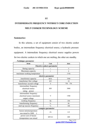
  • 1. 郭珂/Guoke +86 132 9904 2234 Skype: guoke896884090 Page 1 of 25 guoke1207@hotmail.com 5T INTERMEDIATE FREQUENCY WITHOUT CORE INDUCTION MELT COOKER TECHNOLOGY SCHEME Summarize: In this scheme, a set of equipment consist of two electric cooker bodies, an intermediate frequency electrical source, a hydraulic pressure equipment. A intermediate frequency electrical source supplies powers for two electric cookers in which one are melting ,the other are standby. Ⅰ. Technique parameter item Unit data Electric cookers parameter Rating capacity t 5 Maximum capacity t 6 maximum working temperature ℃ 1750 electric parameter transformer capacity KVA 3500 transformer first voltage KV 10 transformer second voltage V 750、750 intermediate frequency electrical source rating power KW 3000 intermediate frequency electrical source maximum output voltage V 1500 working frequency Hz 250 transforming frequency % 98 start-up success frequency % 100 complex parameter fusion ratio(temperature was raised to 1600 ℃) t/h 4.8 power cost of fusion (temperature was raised KW·h/t 600
  • 2. 郭珂/Guoke +86 132 9904 2234 Skype: guoke896884090 Page 2 of 25 guoke1207@hotmail.com to 1600 ℃) working noises db =85 hydraulic pressure system station capacity L 500 working pressure Mpa 13 hydraulic pressure medium grease cooling water system flow quantity t/h 144 water supply pressure Mpa 0.25-0.35 input water temperature ℃ 5-35 output water temperature ℃ <55 Ⅱ. Technical criterion and working condition of equipment The parts of the equipment accord corresponding technical criterion listed behind. 1. GBl0067.3— 88 the basic technical condition of galvanothermy equipment— induction galvanothermy equipment. 2. GBl0063.3— 88 the experiment method of galvanothermy equipment— non-core induction melting cooker. 3. GB5959.3-88 the safety of galvanothermy equipment— special require on inductive and conductive heater and inductive melting equipment. 4. JB4086-85 intermediate frequency non-core induction heat-up use the technical condition of the equipments controlled by electricity. 5. JB / T4280— 93 intermediate frequency non-core induction cooker. 6. GB/T14549-93 the quality of power— the performance and
  • 3. 郭珂/Guoke +86 132 9904 2234 Skype: guoke896884090 Page 3 of 25 guoke1207@hotmail.com technical parameter of the resonance-wave equipment used in electricity network reach the regulation of technology specification book. Ⅲ. Normal working condition of the equipment listing behind 1. Environment a. Altitude is below 1000 m. b. Surroundings temperature is between 5 ℃ and 40℃. c. Relative humidity is not above 90% (25℃). d. No conductive dust, explosive gas and causticity gas which can damage metal and insulation. e. No obvious vibration and jounce. 2. Power supply demand a. Power supply voltage in main circuit is 1OKV, fluctuation is less 5% and three phase imbalance is less 5%. b. Power supply voltage in control system is 220 V and fluctuation is less 5%. c. Power supply voltage in main circuit and control system must be sine wave whose shape aberration is less 10%. 3. The demand of cooling water in outside cycle a. Overall rigidity is less 60 mg equal quantity per liter. b. dissolutive solid substance < 300 mg/L. c. PH 7— 8.5. d. suspension solid substance < lOmg/L.
  • 4. 郭珂/Guoke +86 132 9904 2234 Skype: guoke896884090 Page 4 of 25 guoke1207@hotmail.com e. conductance rate <500µs/cm. f. input water temperature =35℃. Ⅳ. Technique explanation of electric parts The electric parts of equipments consist of electrical source commutation transformer, Intermediate frequency electrical source cabinet, compensation capacitor groups, and high voltage switch cabinet. 1. Electrical source transformer The electrical source transformer is used to drop 11KV high voltage electricity in electric network to one which can fit Intermediate frequency electrical source. The equipment adopts special commutation transformers which self-cooling dipped in oil. 1.1 commutation transformer used for fusion: rating capacity 3500 KVA the first voltage 10 KV, the second voltage 750 V。 impedance in short circuit between 6% and 8% non-load switch installed on the high voltage side and used to regulate voltage by hand can adjust on three stages -5%,0,+5%.
  • 5. 郭珂/Guoke +86 132 9904 2234 Skype: guoke896884090 Page 5 of 25 guoke1207@hotmail.com 1.2. Intermediate frequency electrical source The type of intermediate frequency electrical source in the electric cooker is KGPS -3000 /0.25. Circuit principle drawing is listed below. 2. Intermediate frequency electrical source main loop principle chart 2.1 Commutate part control silicon adopt up to date fold installed radiator groupware as following chart This kind of install mode is more convenience and science to remove and install control silicon .When change control silicon, only loosen tip tighten bolt, you can change anyone control silicon component in groupware. Radiator component has scale which can consult when fasten, and this guarantee right pressure during control silicon and radiator. Moreover, this kind of installs mode minish control silicon groupware
  • 6. 郭珂/Guoke +86 132 9904 2234 Skype: guoke896884090 Page 6 of 25 guoke1207@hotmail.com volume, which makes operation room in electric cabinet bigger. 2.2 Great capacity direct current sieve wave reactor Sieve wave reactor is very important for solid electrical source,it has two function ,the one is to make output current smooth and stable;the other is when athwart change control silicon short circuit,it circumscribe short circuit increase rate and the biggest short circuit 。If sieve wave reactor parameter design inconsequence,iron core material is not good or production techniques do not pass the test ,all those may influence reliability of intermediate frequency electrical source。 2.3 Athwart change circuit adopt great speediness control silicon To guarantee athwart change circuit reliability,athwart change control silicon adopt two big capacity KK silicon in series 2.4. Adopt series-parallel connection compensate circuitry to minish wastage of transmit electricity circuitry To minish intermediate frequency transmit electricity circuitry wastage, athwart change circuit compensate capacitor adopt series-parallel connection, as follows: C1 L Intermediate C2 Frequency output This kind connection can enhance cooker output voltage twice as
  • 7. 郭珂/Guoke +86 132 9904 2234 Skype: guoke896884090 Page 7 of 25 guoke1207@hotmail.com athwart change circuit. And at the same output power output electrical current become only 50% as before, which make intermediate frequency transmit circuitry wastage minish to 1/4. 2.5 Main circuit parameter and component selection foundation When adopt 6 pulse wave rectifiers, commutate control silicon average electrical current can be calculated according to the following formula: Ikpmax=Id max/2.72 Athwart change control silicon average electrical current can be calculate according to the following formula: Ikkmax=0.45XIdmax Choose control silicon standard and select 2.6 Characteristic of intermediate frequency electrical source 2.6.1 Control system total numeric, without continue electricity control Control system adopt ISP program logical array module to integration control. Its core apparatus adopt high performance, high density ,great standard special ASTC-2 integration circuit ,which is made in USA, and this makes all signal dispose and correspondence operation carry out automatism according to program. Replace all kind of continue electricity control
  • 8. 郭珂/Guoke +86 132 9904 2234 Skype: guoke896884090 Page 8 of 25 guoke1207@hotmail.com with data control system to finish the function. 2.6.2 Unique browse frequency model startup mode has 100% startup succeed rate. Athwart change part adopt browse frequency zero pressure soft startup ,which has better performance than common zero pressure soft startup circuit。Browse frequency model startup process as following: before startup,touch off athwart change crystal brake pipe with stimulating signal whose frequency is higher than slot route syntony, moreover control stimulate signal frequency to browse from high to low,when the frequency is near slot route syntony, intermediate frequency voltage is set up .To prevent intermediate frequency voltage startup failure occasionally,our company design automatism startup circuit,ensure 100% startup succeed rate,moreover , its response time is very short,it only takes less than 500 MSEL to finish a automatism startup. 2.6.3 Adjuster with quick respond identity Our company have design particular adjuster in control circuitry whose responding time is very short, the adjuster is completely fit for the use demand of speediness respond in the condition of the load break of intermediate power supply. 2.6.4 Electrical source constant power is output to ensure supernal power
  • 9. 郭珂/Guoke +86 132 9904 2234 Skype: guoke896884090 Page 9 of 25 guoke1207@hotmail.com factor The impedance adjuster is devised especially which can inspect the change of the impedance and deliver it to circuit interior processing figure operation and adjust automatically matching load to make intermediate frequency power supply reach constant power. At the same time, the running power factor of the whole set equipment reaches above 0.93 because of using impedance adjuster in the course of melting. The relation graph of constant power intermediate frequency voltage US and its corresponding power factor φcos is given in following drawing. COS? 0 1050V 1300V Us (Constant power intermediate frequency voltage and its corresponding power factor connection graph) 2.6.5 Having outstanding anti-striking load capacity There leave enough space in choosing main apparatus in system., which guarantee each apparatus outstanding anti-striking capacity。Our firm provides especial device in control part of system on software, and
  • 10. 郭珂/Guoke +86 132 9904 2234 Skype: guoke896884090 Page 10 of 25 guoke1207@hotmail.com this makes system running more stationary and reliable and prevent monocrystalline silicon efficiently from damage of electric impulse while adding material .Thus, the equipment’s good capability of impulsion resistance is ensured and the equipment can run on the safe side in long period. 2.6.6 Perfect and reliable protection function Such protection measure of overflow, overload, over press,phase shortage, lack of voltage of controllable power, too low cooling water pressure, too high temperature of cooling water and too low water flux are provided in this controlling circuitry. These protection functions are analyzed and realized by ASIC-2 integrate circuit, which ensures the sensitivity and reliability of those protection function. This system is water cooling equipment, real time inspection to cooling water on many point has to be carried out for equipment runs on the safe side. Our firm devises a set of characteristic inspect instrument for a special purpose aim at importance of water inspection. Two temperature inspection points is set on each controllable silicon, and the same points is set on each syntonic capacitor and every induction loop. This makes each part of water cooling of this system be inspected at real time. It is impossible to damage part of apparatus which have too high water temperature on one point. 2.6.7 Advanced auto identify function of phase order
  • 11. 郭珂/Guoke +86 132 9904 2234 Skype: guoke896884090 Page 11 of 25 guoke1207@hotmail.com A auto identify circuit of phase order is contained in controllable system, which makes system need not install synchronic transformation and excuse phase order modulation and the job to synchronize while debugging and maintaining. 2.6.8 abundant outside controllable interface It is set on the equipment that Out/In transformation, Auto/Hand control switch and their interface, which can realize auto controlment from long distance conveniently. And outside temperature ring controllable interface is set to combine infrared temperature inspect instrument and temperature auto controlling system, which can realize the auto modulation of program enactment temperature rising to output power of electrical source and makes final calefaction temperature of steel tube reach anticipated temperature. 2.6.9 Light isolation impulse output In controlling system, there are double isolation measures in springing impulse between controlling board to controlling pole of controllable silicon. Light isolation apparatus with its pressure endurance over 2500V is used on controlling board to insulate springing impulse from light or electricity, and transformer groupware with its pressure endurance grade of over 3000V is used on impulse transformer. Even though controllable silicon is stroked out because of over pressure, it has little influence on controlling system.
  • 12. 郭珂/Guoke +86 132 9904 2234 Skype: guoke896884090 Page 12 of 25 guoke1207@hotmail.com 2.6.10 Simple and convenient to debug and maintain The major parameters’settings on controlling board are finished by internal circuit of controlling board. There are only six potentiometer parameters’settings which can be modulated by user. So the controlling board is perfectly universal and reciprocates, and it is simple and convenient to debug and maintain. 2.7 Cooker leaking protection and earthling alarm brake function A special detector of cooker liner’s thickness is set on controlling system. The working theory is to verdict the perfection of cooker liner through leaking current between inductive loops and charging. Because leaking current must amply while cooker liner becomes thin. Alarm current of cooker liner thickness detector can be modulated. Appropriate alarm current must be modulated gradually while it is being used according to different size of cooker and different material of cooker line. Cooker liner thickness detector cann’t runs correctly 100 percent. It can only offer reference of judging cooker liner thickness. The cooker liner thickness detector is connected between side pole and bottom pole directly. 2.8 Compensating capacitor groups
  • 13. 郭珂/Guoke +86 132 9904 2234 Skype: guoke896884090 Page 13 of 25 guoke1207@hotmail.com To minish waste of big current circuit, compensating capacitor groups are set on the position next to electric cooker in basement as possible as they can.. All capacitor are new innoxious water cooling intermediate frequency big capacity capacitors, which have such merit as big capacity of each one, low waste of medium and small area of containing ground. Digital temperature inspecting component is installed on each capacitor, which can auto stop intermediate frequency electric source through working temperature inspected by especial temperature inspection appearance developed by our firm while temperature is over high and alarm signal is come up. Capacitor groups all use big section water cooling copper arrange. Working temperature of copper arranges must not beyond C0 45 to cut down transmission waste of parallel connecting syntonic circuit. Five.Part of electric cooker It contains electric cooker body, water cooling cable, high fire endurance pastern, speedy extrusion equipment of cooker liner and copper arrange of main circuit. 1. cooker body Cooker body contains induction loop, magnetic yoke, cooker frame, leaning oil jar and cooker cover. 1.1 Inductive loop
  • 14. 郭珂/Guoke +86 132 9904 2234 Skype: guoke896884090 Page 14 of 25 guoke1207@hotmail.com The inductive loop is circled by 99.99 percent rectangle copper cube. Insulation on the inductive loop surface is smeared a flat of high strength insulated colophony using static gushing craftwork, whose insulation can endure voltage more than 6000V. Inductive loop is fixed up by lists of bolts sealed around its circumference and insulated supporting bar. After loop is fixed up, its error of circle distance is no more than 2mm. Copper water cooling circles are set on the top and the bottom of inductive loop to make cooker liner material is heated evenly in axial direction and to prolong the working life of cooker liner. On the outside surface of inductive loop, couples of temperature explorer stationeries are welded on waterway subsection to fix up temperature measure component. While one of water way is jammed, alarm is given off immediately and the intermediate frequency electric source ceases automatically. 1.2 Magnetic yoke The magnetic yoke is made up of cold rolled silicon and steel of high magnetism transmit rate. The thickness of silicon and steel is o.3mm. Profile modeling configuration is used in the magnetic yoke, whose internal arc face radian is equal to outer circle’s radian of inductive loop. This make the magnetic yoke can cling to outer side of inductive loop, and inhibit the magnetic field emanated out by loop to decrease magnetic
  • 15. 郭珂/Guoke +86 132 9904 2234 Skype: guoke896884090 Page 15 of 25 guoke1207@hotmail.com block of outer magnetic circuit. The magnetic yoke is hold by stainless steel plates on both sides and stainless steel clamps. It is weld to root. Cooling water cubes are weld on the stainless steel plates on both sides to cool magnetic yoke. The cooling water cube can endure 0.45Mpa water pressure and has no leaking out in 15min. After the magnetic yokes are installed completely, the camber is no more than 4mm, the warp of theoretical center line and practical center line are no more than 3mm. 1.3 cooker frames The cooker frames divide into active part and stationary part. Active cooker frame is used to install inductive loop and magnetic yoke, which is weld by profiled bar and armor plate and utilize framework configuration. The framework has removable cover board, which is convenient for examine and repair. Deepen armor plates are used on the operation flat roof on the top of cooker frame to enhance the intensity and bearing ability of the cooker frame. There is a cooker cover on the top of active cooker frame, and hydraulic pressure driving fashion is used. The ascendance and rotation of it are accomplished by two ole jars to ensure cooker cover to run in gear and reliably The stationary cooker frame is set on the groundsill to hold the active
  • 16. 郭珂/Guoke +86 132 9904 2234 Skype: guoke896884090 Page 16 of 25 guoke1207@hotmail.com cooker frame. There are leaning rolling axes connected to the cooker frame over the stationary cooker frame, which can make active cooker frame rotate 0 95 ahead. A fast cutting valve which can prevent breaking and limit velocity is set on the bottom of the leaning cooker oil jar. In the course of inclining cooker, if the ole jar is broken, the cutting valve which can prevent breaking and limit velocity will act to cut off the returning oil circuit of the oil jar and make the electric cooker state on the original position. There is a very big safety factor remained in the period of dividing. This ensures that the cooker frame has enough rigidity and run placidly when it bears the most loads. Induction winding and charging parameter: Induction winding and charging parameter is optimize designed by special computer ,which guarantee the best electromagnetism coupling efficiency at same capacity. Considering electric cooker need over take, we design that rating capacity is bigger than standard .Only that can guarantee charging liquid surface would not exceed water-cooling circle upper surface at the biggest charging capacity. Since the part above water-cooling circle is not cooled, if the part touches charging for long time, it will produce high temperature, which makes cooker liner craze at water-cooling circle. 2. water-cooling cable
  • 17. 郭珂/Guoke +86 132 9904 2234 Skype: guoke896884090 Page 17 of 25 guoke1207@hotmail.com water-cooling cable joint adopt cool pressure molding techniques to press with copper wind line,which joint fastness,contact resistance small,do not damnify copper wind line. The single tie-in and copper line can endure more than 8t pull Water-cooling cable outer bushing adopt special hinder-burning rubber pipe, which is not flammability. Intension is good,which can endure 0.45Mpa water pressure.,no leak,no break。 material, which smear among circumference and inside induce winding ,has following function: (1)It makes induce winding whole,reduce vibration and noises when work. (2)when charging leak ,it can protect induce winding. (3)It makes for pulling cooker liner. 4. Pulling cooker liner rapidly equipment Pulling cooker liner rapidly equipment,which include tip push block, tip push oil jar and operation framework, is used for getting rid of old ones rapidly. Tip push block,under cooker liner,is linked with tip push oil jar through the bottom of cooker. when pushing out old cooker liner ,turn the electric cooker 90 degree,fix tip push oil jar with bolt and joint flange. Operate handy valve to press oil jar ,then old cooker liner is pushed out .
  • 18. 郭珂/Guoke +86 132 9904 2234 Skype: guoke896884090 Page 18 of 25 guoke1207@hotmail.com Six .hydraulic pressure Including hydraulic pressure pumping station and leaning cooker manipulation platform: Hydraulic pressure pumping station is used for supplying power to leaning cooker, cooker lip drive oil jar, cooker liner push oil jar. Pumping station rating work pressure is 11Mpa. Hydraulic pressure medium is hydraulic pressure oil. Leaning cooker manipulation platform is used for controlling the cooker to lean, turn round, switching cooker lip and pushing cooker liner。 It adopt handle valve, act placidity, no impulsion. All hydraulic pressure components adopt joint venture high quality product. Seven: cooling water system Cooling water system adopts cooling tower of FBNL close type or FKHL open type whose concrete parameter select may refer to the data of sample production. Eight: installation and base map The installation of the facility and base map are showed in attached drawing. Nine: technique datum and drawing
  • 19. 郭珂/Guoke +86 132 9904 2234 Skype: guoke896884090 Page 19 of 25 guoke1207@hotmail.com We supply following technique datum when the equipment leave factory. 1. machine part It includes electric cooker exterior drawing, base drawing, plane lay drawing, land build demand, the data of flat roof and cooling water system, easy damage piece drawing. Equipment fixing and debug instructor, the guidance book of use and maintenance about electric cooker. Hydraulic pressure principle drawing, the guidance book of the Hydraulic pressure system. The guidance book of the water system. 2. electric part It includes the principle drawing of the electric and circuit, exterior wiring diagram, electric component table, the guidance book of intermediate frequency power supply, the guidance book of control system malfunction inspection exclusion. Ten: Equipment beforehand validate and training When all the equipment manufacture is over, we will invite the buyer technician to the equipment manufacture factory, take part in the equipment beforehand check , accept and training. 1. beforehand check and accept content:
  • 20. 郭珂/Guoke +86 132 9904 2234 Skype: guoke896884090 Page 20 of 25 guoke1207@hotmail.com (1) commonly inspection (2) security inspection (3) the cooker assemble dimension examination (4) inductorium manufacture quality examination and insulation, pressure endurance experimentation (5) measurement the electric gap between inductorium and cooker shell (6) measurement insulated resistance between inductorium and cooker shell (7) measurement insulated resistance between inductorium and magnetism yoke (8) intermediate frequency cooker insulated, pressure endurance test (9) pressure test of hydraulic pressure system (10) leaning cooker manipulate test of leaning cooker transmission framework (11) induction winding hydraulic pressure test (12) electric linkage and spillage cooker alarming equipment experiment (13) electric malfunction display, monitor, alarm etc protect functional inspection (14) match inspection, including model, standard, up to grade certificate leaving factory
  • 21. 郭珂/Guoke +86 132 9904 2234 Skype: guoke896884090 Page 21 of 25 guoke1207@hotmail.com (15) supply good range, technique document integrality test 2. Training (1) The seller supply user the following technical training the equipment installation training (2) Electric control design principle training.(Including: electric design protection, inspection, malfunction display) (3) Equipment maintains and daily maintains work training (4) Equipment ordinary malfunction and special malfunction elimination training 3. All the beforehand check and accept item and test data should be got when two sides attend and signature, supply user the data at the same time. 4. Only when all the check work is over and two sides agree to sign it, the seller can package and consignment the equipment Twelve install, debug and the final check and accept. Eleven: Installation, Debug and final check and accept. 1. When the equipment installation is over, our company will send respect specialist install spot to check the installation and precision, and then debug the equipment 2. The seller specialist will train the user employee to handle and repair the equipment at the spot
  • 22. 郭珂/Guoke +86 132 9904 2234 Skype: guoke896884090 Page 22 of 25 guoke1207@hotmail.com 3. The equipment final check and accept should be held at user spot, the item including: (1) all the check item and completely safety check; (2) Induce cooker heat preservation power parameter measurement; (3) Induce cooker heat preservation power measurement,temperature rising productivity measurement (4) Induce cooker electricity consume and melt rate measurement (5) Refrigeration medium temperature rising measurement (6) The cooker component temperature measurement (7) Charging temperature measurement (8) Noises measurement (9) Check after heat condition experiment (10) Alarm system dependability and sensitive degree examination; (11) According to technical demand clausal validate When all the item have been checked, tested, write out the final examination report, both sides get agreement, the contract get into effect Twelve: product quality control measure 1. Our company is strictly according to ISO9001 quality standard at quality control, set up a completely quality system document and get across quality authentication. When we select the oral material and in addition fitting, we set up a whole and up to grade provider, to be sure the
  • 23. 郭珂/Guoke +86 132 9904 2234 Skype: guoke896884090 Page 23 of 25 guoke1207@hotmail.com quality of oral material. 2. In the process of the production, every spare part has quality responsibility track card, which record every step responsibility and the final check .to the pivotal part such as inductor ,magnetism yoke etc, we have special technique regulations, which ensure that only the up to grade part from last working procedure can get across the next. 3. We will checkout the product before leaving factory. Which include appearance examination, mechanism measurement, induce winding insulation checkout, bear the press and water trial. The lean movement of .electric cooker examination cooker lid rise drop and circumrotate examination. 4. Hydraulic pressure system check-out and each intermediate frequency electrical source parameter examination ,when all the examination is up to grade ,the checkout will fill product checkout certificate, and record all kinds of examine data ,which guarantee product quality can trace back Thirteen: product quality guarantee 1. The electric cooker facility is made up with bran-new, high–quality material which can compare with equipment technique standard explanation book; all substantiality facets are fitted with equipment technical standard explaination book. 2. All the main outer fitting of equipment have product check-out
  • 24. 郭珂/Guoke +86 132 9904 2234 Skype: guoke896884090 Page 24 of 25 guoke1207@hotmail.com certification. 3. We guarantee to keep the electric cooker equipment in good repair for twelve month since the final check-out. During the guarantee period, all the malfunction caused by the equipment manufacture badness or low quality of outer fitting, we will repair and change relevant part. 4. We provide 24 hour respond service .we will send to serve the user during 24 hour in the country ,to abroad the time should take transaction go abroad procedure into account depend on the government work efficiency. 5. To be certain stability of production, we provide customers spare part at benefit price which is lower than market price at same time.
  • 25. 郭珂/Guoke +86 132 9904 2234 Skype: guoke896884090 Page 25 of 25 guoke1207@hotmail.com The whole equipment sets includes number device name model quantity 1 Frequency thyristor converter KGPS KGPS-3000KW/0.25KHz 1 2 Link copper Between the power supply to the capacitor 1 3 Capacitor bank 0.25KHz 1 4 Water-cooling cable set 2 5 Induction melting assembled unit GWJ-5.0t 2 6 Hydraulic System 1 7 Crucible mould 2 8 Water Distributor 2 9 Operation Platform 1 10 Furnace leak alarm system 1 11 Lining ejector 1