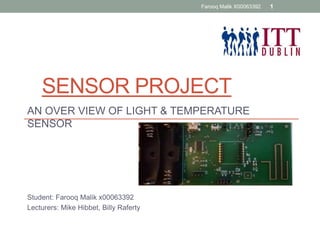
1. SENSOR PROJECT
AN OVER VIEW OF LIGHT & TEMPERATURE
SENSOR
Student: Farooq Malik x00063392
Lecturers: Mike Hibbet, Billy Raferty
Farooq Malik X00063392 1
2. Project Introduction
Low cost Light & Temperature Sensor
Sensor is powered by battery which should last for
two years.
Sensor will operate in temperature rage of -15 to
+55 C
Takes temperature and light every 15 minutes &
transmits every hour to a gateway up to 3KM
away.
Can store a week’s data if gateway is unavailable.
Farooq Malik X00063392 2
3. Requirements
…. The new system will be
compact, self contained ….
…. and easy to fit anywhere
Slide copied from Mike Hibbet presentation. Thanks
4. Hardware Overview
Power Supply Section
MCU MSP430 (28 pins)
Light & Temperature Sensor
RF Module
Farooq Malik X00063392 4
5. Software Overview
• Disable Watchdog Timer
• Setting up Low-Power mode
• Light and Temperature Reading code
• RF module code
• Gateway
Farooq Malik X00063392 5
6. MSP 430 Power Characteristics
• Power consumption @ 2.2V :
• 0.1 μA for memory retention
• 0.4 μA Standby mode ( Vary Low Oscillation)
• 0.7 μA real-time clock mode
• 220 μA / MIPS active mode
• Ultra-Fast Wake-Up from standby-mode in <1 μs
Farooq Malik X00063392 6
7. Light Sensor APDS 9007
• Vcc supply 2 to 3.6V
• Operating temperature : -40°C to
85°C
• Photo current response to wide
dynamic range of 3 lux to 70K lux
• Current consumption 220 approx.
uA at Vcc 2.2
• Output current range 20 to 40uA
depending on LUX
Farooq Malik X00063392 7
8. Temperature Sensor LMT84
• Vcc supply 1.5 to 5V
• Operating temperature : -40°C to
85°C
• -5.5mV /°C gain
• Power consumption 5.4uA
Farooq Malik X00063392 8
9. Power Switch
&
Power MOSFET
Power MOSFET
stops the power
going into the
battery to prevent
battery damage. It
also prevents
power leakage
from the battery to
the mini USB port.
Farooq Malik X00063392 9
10. Managing Power for
MSP430
• An often underutilized method to extend battery life is
dynamic voltage scaling (DVS). With DVS, the input supply is reduced if the MSP430 is
operated at a lower clock speed or placed into a low-power mode. The examples
presented earlier demonstrated that operating with lower input voltages reduces current
consumption and extends battery life. For example, an MSP430 system operating with a
7-MHz maximum clock frequency may require the input voltage to be 3.3 V. If the clock
speed is reduced to 4.6 MHz, the MSP430 requires only a 2.0-V input voltage. If the
MSP430 is placed into low-power mode, the required input voltage is only 1.8 V.
Farooq Malik X00063392 10
11. Managing Power
with LDO
• Figure 4 shows a battery-powered system that uses the TPS780xx to implement DVS
to save battery power. The TPS780xx, which is an LDO with an ultralow quiescent
current of 500 nA, contains a digital input (VSET) that connects directly to the MSP430.
The MSP430 pulls this pin high to set VOUT at 2.2 V and pulls it low to set VOUT at 3.3
V. This configuration allows the MSP430 to adjust its input voltage as its operating
conditions change.
• We can replace Li-Ion with
• Lithium or Alkaline batteries
Farooq Malik X00063392 11
13. Conclusion
• Based on the facts that MSP430 at 5 MHz draws 1.1 mA
in active mode, 1.1 μA in standby and real time clock
mode, we can conclude that 2 AA Alkaline batteries
should be sufficient.
• References:
• MSP430 data sheet
• http://www.ti.com/lit/an/slyt356/slyt356.pdf
• http://www.ece.uah.edu/~jovanov/msp430/slyt218.pdf
• http://www.ti.com/lit/ds/symlink/tps780.pdf
• Mike Hibbet, Sensor Project Introduction
• Billy Raffery, Power supply design
Farooq Malik 13