Study Of High Strength Fibre Reinforced Concrete Beams With Fibre Reinforced ...
KrumheuerLast_Effects of Parameters on Bonding
1. Effects
of
Foil
Thickness
and
Applied
Bonding
Pressure
on
the
Shear
Strength
of
Bonds
Formed
Using
Novel
Reac@ve
Thermite
Foils
Evan
Krumheuer,
T.P.
Weihs
Johns
Hopkins
University
Department
of
Materials
Science
and
Engineering
Mo@va@on
Mechanically
processed
thermite
foils
produce
a
highly
exothermic
reacDon.
When
a
metal
diluent
is
added
to
the
foils,
the
heat
from
this
reacDon
is
sufficient
to
melt
the
diluent
and
form
a
molten
braze.
Poor
foil
quality
can
lead
to:
-‐
Uneven
loading
pressure
-‐
Non-‐uniform
heaDng
-‐
PreferenDal
foil
mass
ejecDon
-‐
Weakened
bond
strength
Sample
Prepara@on
Design
Component
Designed
an
experimental
method
for
comparing
bonds
of
either
varied
thickness
or
applied
bonding
pressure
as
well
as
a
process
for
bonding
large
(4-‐8x
normal)
area
foils.
Foil
Thickness
Applied
Bonding
Pressure
Conclusions
Future
Work
Acknowledgment
This
work
was
supported
by
the
Vehicle
Technologies
Program
of
the
U.S.
Dept.
of
Energy
(DOE-‐VTP)
and
the
U.S.
Army,
No.
DE-‐EE0006441.
I
would
like
to
acknowledge
Alex
Kinsey
and
Kyle
Slusarski
for
their
guidance
and
assistance
with
this
project.
Batch
Comparisons
It
became
apparent
that
foils
originaDng
from
different
tubes
showed
differences
in
reacDve
properDes.
XRD
results
-‐More
Cu2O
character
seen
in
tubes
2
and
3
signifies
incomplete
reacDon
or
oxide
rich
starDng
chemistry.
Foils
were
polished
down
to
a
final
thickness
of
either
400
µm,
700
µm,
1000
µm,
or
1350
µm
±
45
µm.
Redox
foil
between
steel
substrates
in
bonding
apparatus
before
(Lee)
and
aeer
(Right)
igniDon,
with
mass
ejecDon
shown
in
right
figure.
-‐Increasing
thickness
leads
to
increased
bond
strength.
-‐Possible
plateau
of
strength
except
for
outlier.
1. Ball
Mill
Powders
2. Add
30wt%Cu
diluent,
pack
powders
into
tubes
3. Radially
reduce
tubes
through
swaging
4. Cut
tubes
5. Roll
tubes
6. Strip
tubes
to
obtain
flat
foil
Begin
with
Al,
Cu2O,
and
Cu
powders…
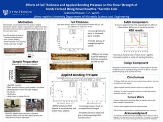
Foils
(1000
µm
thick)
were
tested
with
varied
applied
bonding
pressure.
Pressures
studied
were
15
lbf,
45
lbf,
90
lbf,
and
450
lbf.
-‐1350
µm
thick
foils
wet
the
steel
surfaces
tested
beker
than
any
of
the
thinner
foils
tested.
-‐Higher
applied
bonding
pressure
leads
to
stronger
bonds.
-‐Evidence
of
either
incomplete
reacDon
or
oxide
rich
starDng
materials
in
Tubes
2
and
3.
-‐Perform
more
tests
to
study
the
effect
of
reacDon
area
on
the
shear
strength
of
these
bonds.
-‐Perform
more
analysis
on
tube
to
tube
conDnuity.
-‐EDS
of
broken
bond
surfaces
to
understand
interface
chemistry.
-‐Increasing
pressure
leads
to
increased
bond
strength.
Cross
secDonal
opDcal
microscope
images
of
bonds
formed
with
foils
either
1350
µm
(above)
or
1000
µm
(below)
thick.
-‐1350
µm
foil
shows
superior
welng
of
the
steel
compared
to
1000
µm
foil.
-‐450
lbf
samples
exhibit
highest
%
pressure
drop
and
lowest
mass
ejecDon.
400 600 800 1000 1200 1400
0
50
100
150
200
250
300
350
400
450
400 µm
700 µm
1000 µm
1350 µm
MaxLoad(N)
Foil Thickness (µm)
Unreacted
redox
foil
2”
by
¼”
0 100 200 300 400 500
50
100
150
200
250
300
350 15 lbf
45 lbf
90 lbf
450 lbf
LoadHeld(N)
Applied Bonding Pressure ( (lbf)
0.0 0.5 1.0 1.5 2.0 2.5 3.0 3.5 4.0 4.5
0
20
40
60
80
100
15 lbf
45 lbf
90 lbf
450 lbf
%PressureDrop
Mass Change Per Area (mg / mm
2
)
-‐Variability
of
values
observed
due
to
heterogeneity
in
foil
microstructure.
30 32 34 36 38 40 42 44 46 48 50
2T
Tube 1
Tube 2
Tube 3
Cu2O
Peak
at
~36°
and
masked
by
shoulder
at
~42°
Cu
Cu2O
Al