A Novel Charging Procedure for Embedded System Based Applications
SymposiumPoster [Read-Only]
1. Electronic Measurement System for Spinal Fusion Capacitive Sensor
Introduction
Spinal fusion is a treatment for back pain that surgically joins
together two vertebrae in the spine using a bone graft. During
the procedure, metal bracings are inserted inside the
patient’s body to support the joined section as it heals. These
bracings may be removed after three to six months to begin
the rehabilitation process. However, during this time lapse,
the patient can experience muscular atrophy. It is possible for
patients to start rehab earlier once cartilage forms and
stabilizes the infused area. Current methods of measuring a
patient’s progress (radiography and histology) are unable to
detect the formation of cartilage, so they are not very
accurate. Therefore, an interdigitated capacitive sensor has
been developed to provide greater accuracy and allow
patients to begin rehabilitation as soon as possible. However,
the sensor requires electronic circuitry to interrogate it and
convert the retrieved data into a digital form.
Objective
The interdigitated capacitor will interface with electronic circuitry to read its
capacitance and wirelessly transmit the data to a reader outside of a patient’s body.
The circuitry will be housed with the capacitor on the spinal plate. The preliminary
design of the circuit includes three main stages: a capacitance measuring circuit that
outputs an AC signal, an analog to digital converter, and a radio-frequency circuit to
wirelessly transmit the digital signal. A wireless reader will collect the data from
outside of the patient’s body (Figure 4). The primary objective of the Fall 2014
semester is to complete the first stage of the system.
The Interdigitated Capacitor
An interdigitated capacitor is comprised of interleaved
fingers, as shown in Figure 1. Its capacitance varies based on
First stage of Electronic Circuit
To implement the first stage of the circuit, several capacitance measuring circuits
were analyzed and constructed for testing. Each circuit was tested under various
values of the following parameters: DC voltage supply, AC input amplitude and
Results
The Low-Z Amplifier was constructed on a prototype board (Figure 6)
and will be used to perform initial testing on the interdigitated capacitor
mounted to the spinal plate. Once the capacitor is connected to the
circuit, gentle bending of the spinal plate will be applied using a dynamic
fatigue testing machine. Because the machine utilizes
electromagnetism, it produces electrical noise within a radius of
approximately 1 ft. To protect the circuit’s output signal from noise,
individual wires from an Ethernet cable were connected to the device.
The cable provides insulation for shielding noise, allowing the circuit’s
output signal to be read from a distance outside of the electromagnetic
field.
Conclusion
Eric Tsai, University of Portland
Figure 4. Block Diagram Capacitance Sensing System
Figure 6. Constructed Low-Z Amplifier Circuit
the displacement x of the two sets of fingers. An n-fingered
interdigitated capacitor is equivalent to (n-1) parallel plate
capacitors in parallel (Equation 1). The capacitor will be
mounted to a metal spinal plate (Figure 3), which will be
connected to the bracings that support the spine. The spinal
plate will have a moment applied at both ends. This will
induce bending in the plate that can be measured as strain.
The interdigitated capacitor will vary in capacitance due to
the bending of the plate, indicating the progress of the spinal
fusion: it will increase over time as bone growth provides
additional fixation. The interdigitated capacitor consists of 51
fingers and its range of capacitance is roughly 2.60x10⁻¹⁴ F to
3.34x10⁻¹⁴ F (Figure 2).
frequency, and resistor and capacitor values. Utilizing low value capacitors, such as
Picofarad ones, resulted in noisy or highly attenuated output signals for most of the
circuits. The Low-Z Amplifier (Figure 5), however, accurately measured such
capacitances.
_
______
______
+
V+
V-C2
C1
Vin
Vout
R
Figure 5. Low-Z Amplifier Circuit
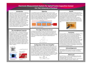
Configuration of the Low-Z Amplifier
The interdigitated capacitor will be connected to the Low-Amplifier circuit as either
C1 or C2 (Figure 5). The circuit and its respective equation are discussed in Larry
Baxter’s Capacitive Sensors: Design and Applications. As shown in Equation 2 below,
Vout will change in value as either C1 or C2 varies. However, C1 should always be
the larger of the two capacitances in order to obtain a noticeable output voltage. If
C2 is significantly larger than C1, Vout may be a very small value, and variances in its
value will be unnoticeable. In addition, C1 and C2 should not be significantly
different in values. For instance, if C1’s capacitance is on the magnitude of 10-9 and
C2’s is 10-15, then Vout will be 106 times larger than Vin. This could result in a voltage
that surpasses the voltage rails of the circuit and clips Vout. Therefore, C1 and C2
should be reasonably close in value to obtain meaningful data.
The Low-Z Amplifier circuit successfully measures capacitances as low as
the Picofarad range. It has yet to be tested on the interdigitated
capacitor or capacitors that are in the Femtofarad range. Once it has
been confirmed that the circuit can operate with these lower
capacitances, research will shift to the second and third stages of the
electronic circuit (digital conversion and wireless transmission).
Preliminary testing has already been performed for both of these stages
using an Arduino microcontroller. Major challenges to consider include
wirelessly transmitting a signal through a human body. Low radio
frequencies may be used for transmission, because they are less
sensitive to environments high in liquid or metal content, as stated in
Atlas RFID Solutions’ “The Basics of an RFID System”. Another challenge
is to scale the electronic circuit to a small integrated circuit that can be
housed with the interdigitated capacitor.
Acknowledgements
Special thanks to Shiley Hall’s Electronics Technician Jared Rees and Dr.
Peter Osterberg for their assistance on the project. I also thank Dr.
Deborah Munro for the opportunity to contribute to the biomedical
Referenced
Figure 1. InterdigitatedCapacitor world!
Atlas RFID Solutions. “The Basics of an RFID System”. Web. July 2014.
Baxter, Larry. Capacitive Sensors: Design and Applications. New York:
IEEE Marketing, 1997. Print. June 2014.
Schenberger, Debbie, Eunice Lee, and Amjad Ramahi. "Measurement of
Spinal Fusion Using MEMS Transduction." (2003): 16. Print.
Equation 1. Capacitance of
Interdigitated Capacitor.
Figure 3. Capacitor Mounted
to Spinal Plate
Figure 2. Close-up of Fabricated
Intergiditated Capacitor
Equation 2. Low-Z Amplifier Circuit Equation