What's New in Teams Calling, Meetings and Devices March 2024
Maxon maxpos feature chart
1. maxon motor control
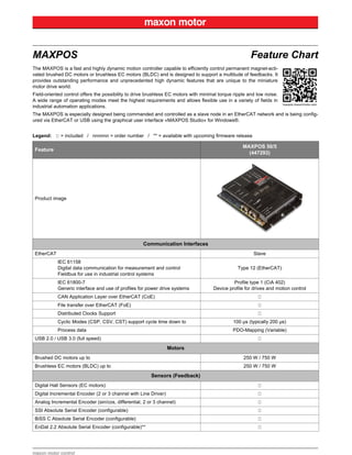
MAXPOS Feature Chart
The MAXPOS is a fast and highly dynamic motion controller capable to efficiently control permanent magnet-acti-
vated brushed DC motors or brushless EC motors (BLDC) and is designed to support a multitude of feedbacks. It
provides outstanding performance and unprecedented high dynamic features that are unique to the miniature
motor drive world.
Field-oriented control offers the possibility to drive brushless EC motors with minimal torque ripple and low noise.
A wide range of operating modes meet the highest requirements and allows flexible use in a variety of fields in
industrial automation applications.
The MAXPOS is especially designed being commanded and controlled as a slave node in an EtherCAT network and is being config-
ured via EtherCAT or USB using the graphical user interface «MAXPOS Studio» for Windows®.
Legend: = included / nnnnnn = order number / ** = available with upcoming firmware release
Feature
MAXPOS 50/5
(447293)
Product image
Communication Interfaces
EtherCAT Slave
IEC 61158
Digital data communication for measurement and control
Fieldbus for use in industrial control systems
Type 12 (EtherCAT)
IEC 61800-7
Generic interface and use of profiles for power drive systems
Profile type 1 (CiA 402)
Device profile for drives and motion control
CAN Application Layer over EtherCAT (CoE)
File transfer over EtherCAT (FoE)
Distributed Clocks Support
Cyclic Modes (CSP, CSV, CST) support cycle time down to 100 µs (typically 200 µs)
Process data PDO-Mapping (Variable)
USB 2.0 / USB 3.0 (full speed)
Motors
Brushed DC motors up to 250 W / 750 W
Brushless EC motors (BLDC) up to 250 W / 750 W
Sensors (Feedback)
Digital Hall Sensors (EC motors)
Digital Incremental Encoder (2 or 3 channel with Line Driver)
Analog Incremental Encoder (sin/cos, differential, 2 or 3 channel)
SSI Absolute Serial Encoder (configurable)
BiSS C Absolute Serial Encoder (configurable)
EnDat 2.2 Absolute Serial Encoder (configurable)**
2. maxon motor control
Commutation EC Motors
Digital Hall Sensors
Digital Hall Sensors + Digital Incremental Encoder
Digital Hall Sensors + Analog Incremental Encoder
Digital Hall Sensors + Absolute Serial Encoder
Absolute Serial Encoder**
Electrical Data
Nominal power supply voltage (+VCC) 10…50 VDC
Nominal logic supply voltage (+VC) 10…50 VDC
Absolute supply voltage limits (+Vmin / +Vmax) 8 VDC / 56 VDC
Output voltage (max.) 0.95 x +VCC
Output current (Icont / Imax <1.5 s) 5 A / 15 A
Pulse width modulation frequency 100 kHz
Sampling rate PI – current controller 100 kHz (10 µs)
Sampling rate PID – speed controller 10 kHz (100 µs)
Sampling rate PID – positioning controller 10 kHz (100 µs)
Max. efficiency 96%
Max. speed DC motor
limited by max. permissible speed (motor)
and max. output voltage (controller)
Max. speed EC motor (sinusoidal) 200'000 rpm (1 pole pair)
Built-in motor choke 3 x 10 μH; 5 A
Inputs / Outputs
Hall sensor signals
H1, H2, H3 for Hall effect sensor ICs (Schmitt trigger
with open collector output)
Digital incremental encoder signals A, A, B, B, I, I (max. 5 MHz)
Sensor signals
(digital incremental, analog incremental, absolute serial (SSI / BiSS /
EnDat**))
A, A, B, B, I, I
Clock+, Clock–
Data+, Data–
Digital inputs 6 (galvanic isolated)
Digital outputs 4 (galvanic isolated)
Hall sensor supply voltage +5 VDC (IL ≤30 mA)
Encoder supply voltage +5 VDC (IL ≤70 mA)
Sensor supply voltage +5 VDC (IL ≤150 mA)
Auxiliary output voltage
+Vcc > 30 VDC: +VOUT = +24 VDC (IL ≤300 mA)
+Vcc < 30 VDC: +VOUT = +VCC - 5 V (IL ≤300 mA)
Status indicators «Axis Status» Bicolor LED (red/green)
Status indicators «EtherCAT Status» Bicolor LED (red/green)
Status indicators «EtherCAT Port Activity/Link State» LED (green)
Feature
MAXPOS 50/5
(447293)
3. maxon motor control
Connections
X1 Power Supply
Molex Mini-Fit Jr. header, dual row (4.2 mm),
2 poles, right angle
X2 Logic Supply
Molex Mini-Fit Jr. header, dual row (4.2 mm),
2 poles, right angle
X3 Motor
Molex Mini-Fit Jr. header, dual row (4.2 mm),
4 poles, right angle
X4 Hall Sensor
Molex Micro-Fit 3.0 header, dual row (3.0 mm),
6 poles, right angle
X5 Encoder Pin header (2.54 mm), 5 x 2 poles
X6 Sensor
Molex Micro-Fit 3.0 header, dual row (3.0 mm),
10 poles, right angle
X7 Signal Input
Molex Micro-Fit 3.0 header, dual row (3.0 mm),
12 poles, right angle
X8 Signal Output
Molex Micro-Fit 3.0 header, dual row (3.0 mm),
8 poles, right angle
X9 EtherCAT IN RJ45 10/100-BASE-TX
X10 EtherCAT OUT RJ45 10/100-BASE-TX
X11 USB USB Type micro B, female
Mechanical Data
Weight (approximate) 302 g
Dimensions (L x W x H) 140 x 103.5 x 27 mm
Mounting holes for screws M4
Environmental Conditions
Temperature – Operation –30…+45°C
Temperature – Extended range
+45…+56°C
Derating: –0.455 A/°C
Temperature – Storage –40…+85°C
Altitude – Operation 0…6’000 m MSL
Altitude – Extended range
6’000…10’000 m MSL
Derating: see Hardware Reference for details
Humidity (condensation not permitted) 20…80%
Directives & Standards
Generic IEC/EN 61000-6-2; IEC/EN 61000-6-3
Applied
IEC/EN 55022 (CISPR22); IEC/EN 61000-4-2;
IEC/EN 61000-4-3; IEC/EN 61000-4-4;
IEC/EN 61000-4-6; IEC/EN 61000-4-8
Environment IEC/EN 60068-2-6; MIL-STD-810F
Safety
UL File Number E243951 and E207844;
unassembled printed circuit board
Reliability MIL-HDBK-217F (MTBF 149'081 hours)
Feature
MAXPOS 50/5
(447293)
4. maxon motor control
Functionality
Operating Modes
Cyclic Synchronous Position Mode (CSP)
Cyclic Synchronous Velocity Mode (CSV)
Cyclic Synchronous Torque Mode (CST)
Profile Position Mode
Profile Velocity Mode
Homing Mode
Features
Feed Forward (acceleration/velocity for inertia and friction compensation)
Field-oriented Motor Control (FOC)
Advanced automatic control settings (Auto Tuning)
Safe Torque Off (STO)
(based on IEC/EN 61800-5-2, without certification)
Digital I/O Functionality
Inputs (configurable)
Touch Probe
Reference switches
Limit switches
Safe Torque Off (STO) inputs
General purpose
Outputs (configurable)
Position Compare**
Control of holding brakes
Safe Torque Off (STO) output
General purpose
Built-in Protection
Current limit
Overcurrent
Excess temperature
Overvoltage
Undervoltage
Voltage transients
Short-circuits of motor cable
Loss of feedback
Following error
Status reporting
Firmware error handling
Feature
MAXPOS 50/5
(447293)
5. maxon motor control
Software
Installation Program MAXPOS Setup
Graphical User Interface MAXPOS Studio
Startup
Regulation Tuning
Diagnostics**
Firmware Update
Motion Commander
I/O Monitor
Parameters
Data Recording
Online Help
Language English
Operating System Windows 8, Windows 7, Windows XP SP3
Accessories (not included in delivery)
275934 Encoder Cable
422827 Ethernet Cable
275878 Hall Sensor Cable
451746 MAXPOS 50/5 Connector Set
459639 MAXPOS USB Stick
275851 Motor Cable
275829 Power Cable
451290 Sensor Cable 5x2core
451291 Signal Cable 12core
451292 Signal Cable 8core
403968 USB Type A - micro B Cable
Feature
MAXPOS 50/5
(447293)