1. J-DCB
Performance Features
Single Position Output Made Easy With
DCB Series Wrap Spring Clutch-Brakes
• Stop Position Accuracy ±1/2°
• Adjustable Output Stop Positions
• Standard Features
- CW or CCW Rotation
- Hub Input - Shaft Output
- Anti-Overrun
Output Does Not Overrun Input
- Anti-Back
Output Does Not Backup
• Stocked with Single Stop
115VAC Solenoid
- 2 and 4 Stop Available for
180° and 90° Output Increments
• 115VAC and 24VDC
Solenoids Standard
- Other Voltages Available
• Dimensionally Interchangeable
With Competitive Units
• 8 Standard Models
DCB-2 – DCB-4
DCB-5 – DCB-5 SUPER
DCB-6 – DCB-6 SUPER
DCB-8 – DCB-8 SUPER
Operation
To start motion, the solenoid is pulsed, moving an actuator arm away from a control collar. This allows the clutch
spring to wrap (wind) down onto the output assembly while the brake spring is unwinding, allowing the output to
drive. Motion is stopped when the actuator returns to its rest position and the control collar rotates into it. This forces
the clutch spring to unwind, releasing the input from the output and wraps the brake spring down, stopping the
output. The anti-back and anti-overrun springs are key items in maintaining position accuracy during operation.
Anti-back will not allow the output to rotate backwards at any time; this eliminates bounce back when stopped.
The anti-overrun allows rotation of the input in one direction only and also keeps the output from rotating faster
than the input. The actual stopping position can be adjusted after installation by moving the splined cam of the
control collar assembly.
The input is a hub with drilled and tapped holes to allow mounting of sprockets, gears, sheaves, etc. The output is a
hollow quill that mounts onto the customer’s driven shaft. The plate must be held in place by a loose-fit pin that does
not allow any side or radial loads that can preload the unit's bearings.
Supers vs. Standard
All units have three primary sintered iron hubs that are oil impregnated; input, brake and an internal hub pinned to
the output shaft. On standard units the oil lubricates the bearing surfaces of the input and brake hubs which ride on
the output shaft, whereas the Supers use needle bearings in the input and brake hubs to increase the radial bearing
load capability. All types require the oil in the hubs to lubricate the springs. The Supers feature hardened steel wear
rings on the primary hubs at the spring crossover point of the clutch, brake and shaft hubs to increase life. The con-trol
Sold & Serviced By:
collar assemblies are glass-reinforced nylon strengthened by steel or aluminum inserts. The actuators are Delrin®
AF on all models.
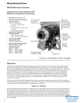
Frame with slots
for torque pin
mounting
Drilled and
tapped holes in
the input (clutch)
hub designed for
bolting sprockets,
sheaves, gears,
etc.
Output shaft
Electrical solenoid
15VAC or 24VDC Actuator arm
Adjustable
single stop
collar; multiple
stop collars
available
Unit Shown is CW Rotation, CCW is Available
Wrap Spring Clutches
Optional
Actuator
Limit Stop
ELECTROMATE
Toll Free Phone (877) SERVO98
Toll Free Fax (877) SERV099
www.electromate.com
sales@electromate.com
2. J-DCB
Product Selection
Basic Selection
Step 1:
Wrap Spring Clutches
To select the correct DCB Series wrap spring, determine the maximum speed (RPM) at
which the unit will operate. Next, determine the load that the output will need to drive
and the system inertia. See Page J-29 for inertia calculations.
Step 2:
Determine the shaft size on which the wrap spring will be mounted. Once this is
determined, the appropriate size DCB can be determined.
Step 3:
Determine clockwise (CW) or counter-clockwise (CCW) rotation, AC or DC solenoid,
number of stops required.
DCB Specifications
Static Maximum Minimum* Anti-Back Anti-Overrun Input Hub Maximum
Torque Input Input Torque Torque Bearing Load
Model In.-Lbs. Speed Speed In.-Lbs. In.-Lbs. Lbs.
DCB-2 25 1800 300 10 10 7.5
DCB-4 125 1200 200 80 25 14
DCB-5 250 750 150 160 45 32
DCB-5 SUPER 250 750 150 125 125 40
DCB-6 500 500 100 300 300 63
DCB-6 SUPER 500 500 100 300 300 65
DCB-8 2500 300 50 600 600 300
DCB-8 SUPER 2500 300 50 600 600 300
* When operating below minimum speeds, system inertias may have to be increased for proper product performance.
Consult factory for application assistance.
115VAC Solenoids 24VDC Solenoids
Current Amps
Resistance Resistance Current
Model Ohms ±10% In-Rush Holding Ohms ±10% Amps
DCB-2 825 .10 .05 104 .23
DCB-4 280 .22 .10 74.0 .32
DCB-5 280 .22 .10 74.0 .32
DCB-5 SUPER 280 .22 .10 74.0 .32
DCB-6 53 .62 .31 40.0 .60
DCB-6 SUPER 53 .62 .31 40.0 .60
DCB-8 53 .62 .31 40.0 .60
Sold & Serviced By:
DCB-8 SUPER 53 .62 .31 25.4 .94
ELECTROMATE
Toll Free Phone (877) SERVO98
Toll Free Fax (877) SERV099
www.electromate.com
sales@electromate.com