Raspberry Pi 5: Challenges and Solutions in Bringing up an OpenGL/Vulkan Driv...
Iai ix scara_120_150_specsheet
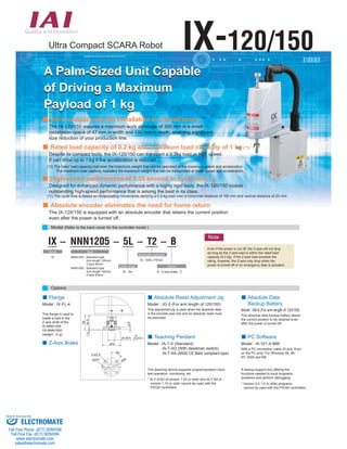
1. Ultra Compact SCARA Robot IX-120/150
A Palm-Sized Unit Capable
of Driving a Maximum
Payload of 1 kg
Ultra compact size for installation in a small space
The IX-120/150 assures a maximum work envelope of 300 mm in a small
installation space of 47 mm in width and 132 mm in depth, enabling significant
size reduction of your production line.
Rated load capacity of 0.2 kg and maximum load capacity of 1 kg (*1)
Despite its compact body, the IX-120/150 can transport a 0.2kg load at high speed.
It can drive up to 1 kg if the acceleration is reduced.
(*1) The rated load capacity indicates the maximum weight that can be operated at the maximum speed and acceleration.
The maximum load capacity indicates the maximum weight that can be transported at lower speed and acceleration.
High-speed performance of 0.35 second in cycle time (*2)
Designed for enhanced dynamic performance with a highly rigid body, the IX-120/150 boasts
outstanding high-speed performance that is among the best in its class.
(*2) The cycle time is based on reciprocating movements carrying a 0.2-kg load over a horizontal distance of 100 mm and vertical distance of 25 mm.
Absolute encoder eliminates the need for home return
The IX-120/150 is equipped with an absolute encoder that retains the current position
even after the power is turned off.
Model (Refer to the back cover for the controller model.)
IX - NNN1205 - 5L - T2 - B
4-ø3.4
45°
ø3H7
ø26
26
1.5 24.5
ø32
0
-0.018
3.5
ø12h7(
Series
IX
Options
Cable length
5L : 5m
Option
B : Z-axis brake : Z
Applicable controller
T2 : XSEL-PX/QX
Type
NNN1205 : Standard type
Arm length 120mm
Z-axis 50mm
NNN1505 : Standard type
Arm length 150mm
Z-axis 50mm
Flange
This flange is used to
install a load to the
Z-axis shaft of the
IX-NNN1205
/IX-NNN1505
(weight: 12 g).
)
Model : IX-FL-4
Absolute Reset Adjustment Jig
Model : JG-5 (For arm length of 120/150)
This adjustment jig is used when the absolute data
in the encoder was lost and an absolute reset must
be executed.
Absolute Data
Backup Battery
Model : AB-6 (For arm length of 120/150)
This absolute data backup battery allows
the current position to be retained even
after the power is turned off.
Teaching Pendant
Model : IA-T-X (Standard)
IA-T-XD (With deadman switch)
IA-T-XA (ANSI/ CE Mark compliant type)
This teaching device supports program/position input,
test operation, monitoring, etc.
* IA-T-X/XD of version 1.20 or older and IA-T-XA of
version 1.10 or older cannot be used with the
PX/QX controllers.
PC Software
Model : IA-101-X-MW
With a PC connection cable (D-sub, 9-pin
on the PC end): For Windows 95, 98,
NT, 2000 and ME.
A startup support tool offering the
functions needed to input programs
/positions and perform debugging.
* Version 5.0.1.0 or older programs
cannot be used with the PX/QX controllers.
Note
Even if the power is cut off, the Z-axis will not drop
as long as the Z-axis load is within the rated load
capacity (0.2 kg). If the Z-axis load exceeds the
rating, however, the Z-axis may drop when the
power is turned off or an emergency stop is actuated.
Z-Axis Brake
Sold Serviced By:
ELECTROMATE
Toll Free Phone (877) SERVO98
Toll Free Fax (877) SERV099
www.electromate.com
sales@electromate.com
2. IX-NNN1205
Ultra Compact SCARA Robot: Standard Type,
Arm Length 120mm, Vertical Axis 50mm
Type Standard type Arm length 120mm Load capacity 0.2kg rated / 1kg maximum
(Example) IX - NNN1205 - 5L - T2 - B
Model
IX-NNN1205-5L-T2 0.35 0.2 1.0
Common Specifications
1 IX-NNN1205
Caution
Allowable
torque
(N•m)
145°
145°
R46.1 R120
R75
115 °
Work envelope
8-pin user connector
SMP-08V-NC by JST
FG
M3, depth 6
85
115 °
(Note 1)Based on PTP operation. In CP operation, the maximum speed is limited.
(Note 2)The cycle time is based on reciprocating movements carrying a 0.2-kg load over
a horizontal distance of 100 mm and vertical distance of 25 mm.
(Note 3)The rated load capacity indicates the maximum weight that can be operated at
the maximum speed and acceleration. The maximum load capacity indicates the
maximum weight that can be transported at lower speed and acceleration.
(Note 4)The thrust in the push mode indicates the force generated when a push
command is executed from the program. The maximum thrust corresponds to
the maximum force generated during normal positioning operation.
(Note 5)The allowable inertial moment indicates an equivalent value measured at the
rotational center of axis 4. The offset between the rotational center of axis 4 and
the gravity center of the tool must not exceed 17.5 mm.
(Note 6)To use the alarm indicator, the user must provide a circuit that uses an I/O output
or other signal to apply 24 VDC to the LED terminal in the user wiring connector.
Model specification items Series Type Cable Length Applicable controller Options
Models/Specifications
Dimensions
5 4
0
16
A A
ø8h7(-0.015)
A-A section
Detail view of vertical axis tip (*3)
Reference
surface
Applicable Controller Specifications
Axis
configuration
Arm length
(mm)
Work
envelope
Motor
capacity
(W)
Positioning
repeatability
(mm)
Cycle time
(sec)
(Note 2)
Load capacity
(kg) (Note 3)
Axis 3
Push thrust (N)
Axis 4
Allowable load
Maximum
operating
speed
(Note 1)
Applicable
controller
Power-supply
voltage
Page
XSEL-PX
XSEL-QX
Feature
SCARA + 2 robot axes
can be controlled.
Conform to safety category 4.
Three-phase
200VAC
Reference
surface
Maximum I/O
points (input/output)
192 points
/192 points
➝Back
cover
Encoder type
User wiring
User tubing
Alarm indicator (Note 6)
Absolute
8-core, AWG26 cable with shield / Connector: SMP-08V-NC (JST)
Air tube (O.D. ø3, I.D. ø2) x 2 (Normal working pressure 0.7MPa)
Operating temperature/humidity
Robot weight
Cable length
Temperature 0~40°C, humidity 20~85% RH or less (non-condensing)
2.7 kg
5L : 5m
Small red LED indicator x 1 (24VDC must be supplied.)
Rated
Push
mode
(Note 4)
Maximum
thrust
(Note 4)
Allowable
inertial
moment
(kg•m2)(Note 5)
Maximum
9.8 17.8 0.000386 0.13
Axis 1
Axis 2
Axis 3
Axis 4
Arm 1
Arm 2
Vertical axis
Rotating axis
45
75
-
-
12
12
12
60
±115°
±145°
50mm
±360°
±0.005
(XY)
±0.010
±0.005
2053mm/ s
(Composite speed)
720mm/ s
1800°/ s
4.5
120
(62)Cable wiring space
ø15
7.5
Alarm
indicator
(*2)
35
Quick connector
joint ø3 (white)
Quick connector
joint ø3 (black)
Quick connector
joint ø3 (white)
Quick connector
joint ø3 (black)
3
33.5
240.5
90.5
50
126
42
19.5
47
18
2-M3, depth 6
Same on the
opposite side (*1)
(48.8)
132
125
75
86.5
45
24
8
30
39
317.5
55.3
(322)
125 (148.2)
60.5 50st 26 125.7
*1: The 2-M3 hole (depth 6) passes through the arm. If the mounting screw is too long, the screw will contact the internal mechanical parts. Exercise caution.
*2: To illuminate the alarm indicator, the user must provide a wiring that uses an I/O output signal from the controller to apply 24 VDC to the LED terminal in the user wiring connector.
*3: The vertical axis does not come with a brake. If the power or servo is turned off, the vertical axis may drop. Exercise caution.
Sold Serviced By:
ELECTROMATE
Toll Free Phone (877) SERVO98
Toll Free Fax (877) SERV099
www.electromate.com
sales@electromate.com
3. IX-NNN1505
Ultra Compact SCARA Robot: Standard Type,
Arm Length 150mm, Vertical Axis 50mm
Arm length 150mm
Type Standard type Load capacity 0.2kg rated / 1kg maximum
Model specification items Series Type Cable Length Applicable controller Options
(Example) IX - NNN1505 - 5L - T2 - B
Models/Specifications
Model
Common Specifications
Dimensions
16
Applicable Controller Specifications
Caution
Rated
Allowable
torque
(N¥m)
8-pin user connector
SMP-08V-NC by JST
FG
M3, depth 6
125
(Note 1)Based on PTP operation. In CP operation, the maximum speed is limited.
(Note 2)The cycle time is based on reciprocating movements carrying a 0.2-kg load over
IX-NNN1505 2
a horizontal distance of 100 mm and vertical distance of 25 mm.
(Note 3)The rated load capacity indicates the maximum weight that can be operated at
the maximum speed and acceleration. The maximum load capacity indicates the
maximum weight that can be transported at lower speed and acceleration.
(Note 4)The thrust in the push mode indicates the force generated when a push
command is executed from the program. The maximum thrust corresponds to
the maximum force generated during normal positioning operation.
(Note 5)The allowable inertial moment indicates an equivalent value measured at the
rotational center of axis 4. The offset between the rotational center of axis 4 and
the gravity center of the tool must not exceed 17.5 mm.
(Note 6)To use the alarm indicator, the user must provide a circuit that uses an I/O output
or other signal to apply 24 VDC to the LED terminal in the user wiring connector.
Axis
configuration
Arm length
(mm)
Work
envelope
Motor
capacity
(W)
Positioning
repeatability
(mm)
Cycle time
(sec)
(Note 2)
Load capacity
(kg) (Note 3)
Axis 3
Push thrust (N)
Axis 4
Maximum Allowable load
operating
speed
(Note 1)
Applicable
controller
Power-supply
voltage
Page
XSEL-PX
XSEL-QX
Feature
SCARA + 2 robot axes
can be controlled.
Conform to safety category 4.
Three-phase
200VAC
Maximum I/O
points (input/output)
192 points
/192 points
➝Back
cover
Encoder type
User wiring
User tubing
Alarm indicator (Note 6)
Absolute
8-core, AWG26 cable with shield / Connector: SMP-08V-NC (JST)
Air tube (O.D. ¿3, I.D. ¿2) x 2 (Normal working pressure 0.7MPa)
Operating temperature/humidity
Robot weight
Cable length
Temperature 0~40¡C, humidity 20~85% RH or less (non-condensing)
2.7 kg
5L : 5m
Small red LED indicator x 1 (24VDC must be supplied.)
0.35 0.2 1.0
Push
mode
(Note 4)
Maximum
thrust
(Note 4)
Allowable
inertial
moment
(kg¥m2)(Note 5)
Maximum
9.8 17.8 0.000386 0.13
Axis 1
Axis 2
Axis 3
Axis 4
Arm 1
Arm 2
Vertical axis
Rotating axis
75
75
-
-
12
12
12
60
–125¡
–145¡
50mm
–360¡
–0.005
(XY)
–0.010
–0.005
2304mm/ s
(Composite speed)
720mm/ s
1800¡/ s
IX-NNN1505-5L-T2
*1: The 2-M3 hole (depth 6) passes through the arm. If the mounting screw is too long, the screw will contact the
internal mechanical parts. Exercise caution.
*2: To illuminate the alarm indicator, the user must provide a wiring that uses an I/O output signal from the controller
to apply 24 VDC to the LED terminal in the user wiring connector.
*3: The vertical axis does not come with a brake. If the power or servo is turned off, the vertical axis may drop. Exercise caution.
150
7.5
5 4
0
¿8h7(-0.015)
¿15
35
90.5
3
33.5 116.5
270.5
75 75
30
50
(148.2) (48.8)
126
18
8
39
19.5
42
47
317.5
55.3
(322)
125
60.5 50st 26 125.7
A A
85
R75
R150
R45.1
125¡
125¡
145¡
145¡
Reference
surface
Reference
surface
(62)Cable wiring space
Alarm
indicator
(*2)
Quick connector
joint ¿3 (white)
Quick connector
joint ¿3 (black)
Quick connector
joint ¿3 (white)
Quick connector
joint ¿3 (black)
2-M3, depth 6
Same on the
opposite side (*1)
A-A section
Work envelope
Detail view of vertical axis tip (*3)
4.5
132
24
Sold Serviced By:
ELECTROMATE
Toll Free Phone (877) SERVO98
Toll Free Fax (877) SERV099
www.electromate.com
sales@electromate.com
4. Catalog No.: IX-CJ0090-1A-Jan3106-1
Controller XSEL-PX/QX
Capable of controlling a SCARA robot and up to two single-axis robots
The XSEL-PX/QX performs complex controls with ease, such as controlling
a SCARA robot simultaneously with a single-axis robot assembled underneath,
or operating a SCARA robot and two-axis cartesian robot at the same time.
Ultra compact size
Despite being a 6-axis controller, the XSEL-PX/QX comes in a slim body
(W 340 mm H 195 mm D 125.3 mm), and these dimensions correspond to
the size of IAI’s 4-axis or smaller controller.
Direct connection to DeviceNet, CC-Link, ProfiBus or Ethernet
The XSEL-PX/QX can be directly connected to various field networks to perform
centralized data control or exchange of signals with the various devices
connected to the network.
XSEL - PX6 - NNN1205 - 200A - 100A - DV - N1 - EEE - 2 - 3
Series
XSEL
IX actuator type
Motor output of axis 5
20A~750AL
: 20W~750W, absolute
20I~750IL
: 20W~750W, incremental
* Axis 5 can be used only when a
5-axis or 6-axis controller is used.
NNN1205 : Standard type
Arm length 120mm
Z-axis 50mm
NNN1505 : Standard type
Arm length 150mm
Z-axis 50mm
Network support
DV: DeviceNet
CC: CC-Link
PR: ProfiBus
ET: Ethernet
(Blank)
: No network support
Motor output of axis 6
20A~750AL
: 20W~750W, absolute
20I~750IL
: 20W~750W, incremental
* Axis 6 can be used only when a
6-axis controller is used.
Standard I/O
N1 : 32 input points/16 output points
(NPN specification)
P1 : 32 input points/16 output points
(PNP specification)
E : Not installed
Power-supply voltage
3 : Three-phase 200VAC
I/O flat cable length
2 : 2m
3 : 3m
5 : 5m
0 : Not supplied
Expansion I/O
* Refer to the separate
controller catalog.
Controller type
PX4 : High-output 4-axis type
PX5 : High-output 5-axis type
PX6 : High-output 6-axis type
QX4 : 4-axis type conforming
to safety category
QX5 : 5-axis type conforming
to safety category
QX6 : 6-axis type conforming
to safety category
Features
Controller type
Specifications External Dimensions
Connectable axes
Total output when maximum
number of axes are connected
Control power input
Motor power input
Power capacity (*1)
Safety circuit configuration
Drive-source cutoff method
Enable input
Position detection method
Speed setting (*2)
Acceleration/deceleration setting
Programming language
Number of program steps
Number of positions
Number of programs (multitasking)
Operating temperature / humidity
Controller weight (*3)
Standard specification
PX4
Global specification
PX5 / PX6 QX4 QX5 / QX6
+ single-axis robot
SCARA only + single-axis robot
2400W
SCARA only SCARA
SCARA
200/230VAC, single-phase, -15%, +10%
200/230VAC, three-phase, -10%, +10%
310VA 3350VA 310VA 3350VA
Redundant configuration
not supported
External safety circuit
Redundant configuration
not supported
Internal cutoff relay
Contact-B input
(internal power supply type)
Contact-B input
(external power supply type, redundant)
Incremental encoder / absolute encoder
1mm/ sec ~ 2000mm/ sec
0.01G ~ 1G
Super SEL Language
6000 steps (total)
4000 positions (total)
64 programs (16 programs)
0~40C¡, 10~95% (non-condensing)
5.2kg 5.7kg 4.5kg 5kg
*1 For the PX4 and QX4, the value indicates the power capacity when one IX-NNN1205/1505
is operated. For the PX5, PX6, QX5 and QX6, the value indicates the power capacity when
one IX-NNN1205/1505 and two 750-watt axes are operated.
*2 The maximum limit varies depending on the actuator type.
*3 The controller weight includes the absolute battery, brake mechanism and expansion I/O box.
3
* The dimensions below do not include expansion I/Os.
Please contact IAI should you require expansion I/Os.
(80)
125.3
3-¿5
49.5 75 75 49.5
5
195
186
180 265
249
3-¿5
28 75 75 28
5
180
195
186
206
222
PX 4-axis specification
QX 4-axis specification
Side view
(Common to PX/QX)
125.3
(80)
3
3-¿5
22 120 120 22
5
195
186
180
284
300
3-¿5
45.5 75 75 45.5
5
195
186
180
241
257
PX 6-axis specification
QX 6-axis specification
Side view
(Common to PX/QX)
Sold Serviced By:
ELECTROMATE
Toll Free Phone (877) SERVO98
Toll Free Fax (877) SERV099
www.electromate.com
sales@electromate.com