1. 2015 Radio Controlled Quadcopter
Advisor: Hamid Shahnasser
School of Engineering
Donald Wu Eduardo Romero-Pacheco Ricky Huynh
San Francisco State University
Department of Electrical Engineering
Introduction
A Quadcopter or a Multirotor is an aerial
vehicle that is lifted and propelled by four
motors. Our Quadcopter uses a “x” orientation
formation and have two sets of identical fixed
pitched propellers, 2 propellers going counter
clockwise and the other two in the opposite
direction going clockwise. Implementing the
propeller in this form helps get the multirotor
to hover and to achieve stability. The control
of the vehicle’s motion is controlled by
altering the rotation rate of one or more
motors in other words the revolution per
minute, rpm. With higher rpm, it is possible to
carry heavier payloads such as a camera for
photography, inspections and surveillance.
Objective
• Implementing as much degree of freedom
as possible which includes the three angles,
roll, pitch and yaw.
• Stabilizing the quadcopter by using a
MPU6050 gyroscope (gyro) and
accelerometer..
• Maintaining low cost while maximizing the
performance
• Carry payloads such as cameras and
packages.
Design Requirement
o
• Larger motors for heavy lifting
• Quadcopter should be as light weight as
possible
• System shall not weigh more than 1.25kg
• Embody the simplest principle of operation
to control degree of freedom and motion.
• X frame arm layout
• Stability
• Quadcopter can lift a ½ pound box (see
improvement)
• System shall be equipped with a first
person view camera (See Improvement)
Figure 1: Block Diagram of UAV
Figure 2: Overall Sketch of the System
General Control Information
Pulse Width Modulation on the microcontroller sends out
signal to the four electronic speed controllers yielding
output signal to the four motors. This system is a radio
controlled system which requires a transmitter and a
receiver for communication.
Transmitter Control
The altitude or throttle is controlled by increasing the
vertical position of the stick on the left side of the
transmitter. Normally the stick starts at 0 throttle position
where the motors will not spin until it is armed by
pushing the yaw stick to the bottom right for 5 seconds.
The Yaw is controlled by moving the throttle stick to the
left or right. The pitch is controlled by the elevator
channel. Doing so will move the aerial vehicle forward.
Lastly the roll is controlled by the Aileron channel.
Doing so will move the quadcopter to the right or left.
Figure 3: Overall Quadcopter
Results
Quadcopter hovered at 6 inches but flipped over at
55% throttle. This is due to the fact that our P
values for our PID tuning was too high and
inaccurate. Secondly, our gyroscope and
accelerometer in our MPU-6050 was too sensitive
to certain angles of our quadcopter which sends out
new errors to compensate for the stability.
Improvement
• Implement more stable PID values for roll, pitch
and yaw.
• Decrease the weight of our quadcopter to
maximize better performance and lift off at
exactly 50% throttle.
• Have our quadcopter lift a ½ pound box
• Equip quadcopter with first person view camera
• Fly without flipping over at 55% throttle.
• Equip a sensor that will prevent our quadcopter
from bumping into things
• Equip a GPS to track where the location of the
quadcopter is.
• Create an application that will measure the
altitude and monitor the battery consumption.
Testing
Figure 4 shows a GUI that calculates the proportional
integral derivative of our quadcopter. The software also
calibrates the accelerometer and the gyroscope with one
click of a button. It also monitors the behavior of the four
after we tweak the values for the PID.
Figure 4: MultiWii Graphical User Interface
Figure 5: Gyro and Accelerometer Sensor Graph
In figure 5, the sensor graph indicates the signal waves for
the roll, pitch and Yaw. This tells us how much vibration
the MPU6050 is sensing.
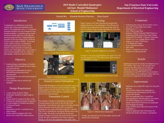
Figure 6: Tethered Down Quadcopter
Testing the transmitter to see if the rudder, elevator and
aileron stick is functional.
Component
• NTM Prop Drive Series 28-26 1100 kv/ 252 w
• Afro ESC 30 Amp Multi-rotor Motor
• Breadboard 1.9” x 1.3”
• 10x4.5 Black Props Pack
• Spektrum AR610 4-Channel DSMX Receiver
• Hobbyking X650F Glass Fiber Quad 550mm
• Spektrum DX5e DSMX 5 Channel Transmitter
• Usmile 3 in 1 Low Voltage Buzzer Alarm
• Zippery 35C series 2700 4S lipo
• Li-24 Balanced Charger
• Power Distribution Board
• MPU-6050
• Battery T connection convertor
• Arduino Uno Microcontroller