JST Analysis of Engine Mount Vibrations Using FEA
•
0 likes•43 views

This paper analysis the engine vibration on the engine mount for heavy duty engines, in vehicle chassis mount of engine is major role So, vibration design of engine mount is one of the main items on the phase of vehicle development, the design should be optimized considering various design variables and uncertainties. In the study, design optimization of engine mount for Heavy duty vehicle, that present will model in proE software and execute Model in 10 modules and Harmonic analysis are in ansys bench work, Here we conclude to results change a material of engine mount frame present was steel to aluminum alloy to reduce the weight and cost ratio, then increase the strength of the engine mount.

Recommended
Recommended
More Related Content
What's hot
What's hot (20)
Viewers also liked
Viewers also liked (12)
Similar to JST Analysis of Engine Mount Vibrations Using FEA
Similar to JST Analysis of Engine Mount Vibrations Using FEA (20)
Recently uploaded
Recently uploaded (20)
JST Analysis of Engine Mount Vibrations Using FEA
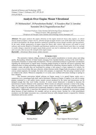
- 1. Journal of Science and Technology (JST) Volume 2, Issue 2, February 2017, PP 28-33 www.jst.org.in www.jst.org.in 28 | Page Analysis Over Engine Mount Vibrational JV.Mohanachari1 , D.Purushottam Reddy2 , S.Vasudeva Rao3 ,U.Jawahar Surendra4 ,Dr.G.Nagamalleswara Rao5 1,3 (Assistant Professor ,Gates Institute Of Technology,Gooty,Anantapur,A.P) 2,4 (Guest Lecturer, SKU,Anantapur,A.P.) 5 (Professor & Principal, Gates Institute Of Technology,Gooty,Anantapur,A.P Abstract: This paper analysis the engine vibration on the engine mount for heavy duty engines, in vehicle chassis mount of engine is major role So, vibration design of engine mount is one of the main items on the phase of vehicle development, the design should be optimized considering various design variables and uncertainties. In the study, design optimization of engine mount for Heavy duty vehicle, that present will model in proE software and execute Model in 10 modules and Harmonic analysis are in ansys bench work, Here we conclude to results change a material of engine mount frame present was steel to aluminum alloy to reduce the weight and cost ratio, then increase the strength of the engine mount. Keywords – vibrational, Motor mount, isolate structure I. INTRODUCTION The automotive industry obliges producers to give careful consideration to traveler solace and riding quality. Resounding vibration of body boards emerging from lopsided burdens existing in the motor body is increased by frameless or unitary body development. This has constrained architects to guide their consideration regarding the advancement of superb motor mounting gadgets keeping in mind the end goal to guarantee that enhanced solace in riding and hushing might not be balanced by exhausting vibration impacts. In all the Chassis contains a many sub parts they are associated by casings, a sub casing is a basic segment of a vehicle, for example, a car or an air ship, that uses a discrete, isolate structure inside a bigger body-on-casing or unit body to convey certain segments, for example, the motor, drive prepare, or suspension. The sub casing is darted as well as welded to the vehicle. Whenever catapulted, it is in some cases outfitted with elastic bushings or springs to hose vibration. The foremost motivations behind utilizing an Engine mount, is to spread Engine stacks over a suspension over a monologue body shell, and to disconnect vibration of Engine. It implies a car with its energy prepare contained in a sub outline (motor mount), powers produced by the motor and transmission can be damped enough that they won't bother travelers .A motor mount framework is intended to decrease the transmission of motor vibration to the suspension. Motor mounts are utilized to associate a motor to the casing. They are typically made of elastic and metal. A motor mount must fulfill two basic yet clashing criteria. To begin with, it ought to be hardened and exceptionally damped to control the sit still shake and motor mounting reverberation. Additionally, it must have the capacity to control, similar to a safeguard, the movement coming about because of load conditions, for example, and go on uneven streets. Second, for a little plentifulness excitation over the higher recurrence run, a consistent however softly damped mount is required for vibration detachment and traveler comfort. Meshing Model Fixed Supports Shown In Figure
- 2. Journal of Science and Technology www.jst.org.in 29 | Page MESHING SIZE MIN SIZE 2.00mm MAX SIZE 4.00mm MESHING ELEMENT TETRAHEDRONS TOTAL NODES 121265 TOTAL ELEMENTS 821498 II. PROCEDURE TO PERFORM BY ANSYS III. RESULTS AND DISCUSSIONS A. 3.1 STATIC STRUCTURAL ANALYSIS FOR STEEL 1) 3.1.1 DEFORMATION 3.1.2 STRESS
- 3. Journal of Science and Technology www.jst.org.in 30 | Page 2) 3.2.1 MODE SHAPE 1 3.2.2 MODE SHAPE 2 3) 3.2.3 MODE SHAPE 3 3.2.4 MODE SHAPE 4 4) 3.2.5 MODE SHAPE 5 3.2.6 MODE SHAPE 6 5) 3.2.7 MODE SHAPE 7 3.2.8 MODE SHAPE 8
- 4. Journal of Science and Technology www.jst.org.in 31 | Page 6) 3.2.9 MODE SHAPE 9 3.2.10 MODE SHAPE 10 B. 3.3 HARMONIC ANALYSIS FOR STEEL 1) 3.3.1 DEFORMATION 3.3.3 STRESS 2) 3.3.2 FREQUENCY OF DEFORMATION 3.3.4 FREQUENCY OF STRESS 3.4 Static Structural Analysis For Aluminum Alloy 3) 3.4.1 DEFORMATION 3.4.2 STRESS 8.5 4.5MODEL
- 5. Journal of Science and Technology www.jst.org.in 32 | Page Analysis For Aluminum Alloy 4) 3.5.1 MODE SHAPE 1 3.5.2 MODE SHAPE 2 5) 3.5.3 MODE SHAPE 3 3.5.4 MODE SHAPE 4 6) 3.5.5 MODE SHAPE 5 3.5.6 MODE SHAPE 6 7) 3.5.7 MODE SHAPE 7 3.5.8 MODE SHAPE 8
- 6. Journal of Science and Technology www.jst.org.in 33 | Page 8) 3.5.9 MODE SHAPE 9 3.5.10 MODE SHAPE 10 C. 3.6 HARMONIC ANALYSIS FOR ALUMINIUM ALLOY 1) 3.6.1 DEFORMATION 3.6.3 STRESS 2) 3.6.2 FREQUENCY FOR DEFORMATION 3.6.4 FREQUENCY FOR STRESS IV. CONCLUSION In this work, computational modeling and simulation of an available engine mount frame was performed to gain an understanding of the harmonic response on an engine mounts and to evaluate the effectiveness of current market available solutions. Special attention was given to the correct modeling of nonlinear effects on the vibrational behavior of the mount. The experimental harmonic analysis of the mount revealed the presence of two distinct regions in the engine operating frequency in which the mount had an almost constant on mounting area and another where the existence of contact between on engine constrain. Then, Done a model analysis to finding a natural frequency of a range between a maximum and minimum frequency. Value is 0 to 500 Hz in between the mode shapes 10. Another type of harmonic analysis for material changed mount that also done same model and harmonic analysis are done; by we are comparing result to find the better model and proposed a aluminum alloy to better model. REFERENCES [1] R Singh “Dynamic design of automotive systems: Engine mounts and structural joints” Department of Mechanical Engineering, Ohio State University, Columbus, OH 43210, Journal of Automobile Engineering Volume 24, (2000) 299 – 319. [2] Jun Lan “Multi-Body Nonlinear Analysis for Engine Vibration Simulation” Journal of Shock and Vibration , 192(2), Feb 2001, 145-154. [3] Chang Yong Song [4], “Design Optimization and Development of Vibration Analysis Program for Engine Mount System”, volume 84, march 2006. [4] Q. Li and J.C. Zhao [5], “Experimental Study on the Vibration Isolation Characteristics of Hydraulic Engine Mounts”, experiment techniques, Feb 2010. [5] D.H. Lee [6], “Design Sensitivity Analysis and Optimization of an Engine Mount System Using a frequency response functions (FRF) Based Sub structuring”, Journal of Sound and Vibration, 255 (2002) 383-397. [6] J. E. Colgate and C.T. Chang [7], “Modeling of a Hydraulic Engine Mount Focusing on Response to Sinusoidal and Composite Excitations”, Journal of Sound and Vibration, 184 (1995) 503-528. [7] LS-DYNA Keyword user’s manual, version 970- Livermore Software Technology Corporation.