1. Abstract
The BSU optical tweezer project is currently in its final phase of building and we expect it to be
ready by next summer for research purposes. In an optical tweezers experiment a small
polystyrene bead with diameter in the order of few microns is trapped with help of laser. When
an external force is applied, this bead get displaced within the trap and causes the laser to
deflect. The laser deflection is proportional to the force exerted on the bead, therefore in an
experiment to estimate the force exerted on the bead we have to measure the displacement of
the laser. In this project we discuss how we design our optical elements to direct the deflected
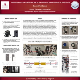
laser beam to a position sensing detector. The polarization of the laser is rotated with couple of
quarter-wave plates so that a polarizing beam splitting cube can be used to direct the laser
vertically upward from the table into the detector. To capture the laser in the small sensor area
of the detector a custom machined arm was created. This “arm” also contained a manually
adjustable stage that can move in two dimensions. In the alignment process, the power of the
laser was reduced using a neutral density filter to match the sensitiveness of the detector. A lens
was positioned to focus the laser beam directly into the photodiode to ensure a more accurate
measurement. Once the laser alignment of the trap is completed the photodiode will be able to
measure the displacement of the laser to estimate the force of the trapped object.
Need for Detector Arm Assembling the Components
The laser deflection is detected and measured
by a position sensing detector.
In order to measure the deflection the laser
spot has to be centered on the detecting area
before each reading. To achieve this the
detector has to be mount on a two dimensional
translation stage.
The design of the stage requires an “arm” that
must be constructed to position the
photodiode directly above the polarized beam
splitting cube.
We determined the length of the “arms” and
the size of drill hole correspond to the related
screw holes for the stage and position sensing
detector based on the design. Then put
together a schematic for the arms.
We constructed the arms out of an aluminum
blocks using a machine drill and saw.
Measuring the Laser Deflection due to the Motion of a Bead held by an Optical Trap
Devon West-Coates
Mentor: Thayaparan Paramanathan
Department of Physics, Bridgewater State University
Supported by Adrian Tinsley Program
Acknowledgements
First, the arms were assembled with two
dimensional translation stage to provide proper
movement so that the defected laser can be
detected and centered.
A lens to focus the deflected laser and a neutral
density filter to reduce the laser intensity was
added to the vertical aluminum post before
securing the detector arm to the post.
The Adrian Tinsley Program, James Munise, Patricia Benson and Williams Lab at Northeastern University
The neutral density filter was selected to
reduce mW order laser power into W order
so that the detector can handle the power.
Laser Path in the Optical Tweezers Set-up
Laser Polarization is used to Direct the Deflected Beam Upward
Construction of Detector Arm
Quarter Wave Plate
rotates the
polarization by 45
Polarizing Beam
Splitting CubeMicroscopic Objectives
and flow cell
Vertically Polarized
Laser Beam
Horizontally Polarized
Laser Beam
2D Translational Stage
Position Sensing Detector
Neutral Density Filter
Plano Convex Lens
(Focal Length = 100 mm)
Polarizing Beam
Splitting Cube
Completed Post
Assembly (Left)