SlideShare a Scribd company logo
1 of 1
Download to read offline
GP Technologies Ltd.
© 2016
Daniel Lang, P.Eng. dlang@gptechnologies.com
GP Technologies Ltd. 200 9016 51 Ave. Edmonton, AB
GP TECH
Power System Experts
Acronyms:
1. SCR – Silicon Controlled Rectifier
2. GCT – Gate Commutated Thyristor
3. SGCT – Symmetrical Gate Commutated
Thyristor
4. GTO – Gate Turn-Off Thyristor
5. IGBT – Insulated Gate Bipolar Transistor
6. IGCT – Insulated Gate Commutated Thyristor
7. IEGT – Injection Enhanced Gate Transistor
Current Source Inverter (CSI)
A current source inverter uses SCRs, GCTs, or
SGCTs to rectify the input voltage (known as an
active front end). A large inductor forms the DC link,
which stores energy and maintains constant current
for the inverter section. The inverter section uses
GTOs or SGCTs to create the pulse width modulated
output signal.
Voltage Source Inverter (VSI)
A voltage source inverter uses diodes to rectify the
input voltage. A large capacitor forms the DC link,
which stores energy and maintains constant voltage
for the inverter section. The inverter section uses
IGBTs, IGCTs, or IEGTs to create the pulse width
modulated output signal.
Dynamic Response
Def.: system response to change in operating point
from one steady state condition to another, following
a change in system variables (load torque, voltage,
current, etc.)
 Dynamic response of a drive system is limited by
mechanical inertia and electrical inductance.
 Time rate of change of current proportional to
size of inductor
 CSI design includes large inductors for energy
storage and signal conditioning, resulting in poor
dynamic response.
 VSI utilize a DC bus capacitor and are able to
provide instantaneous current, vastly improving
drive dynamic response.
Power Quality
 VSI utilizes a 24 or 36 pulse phase shifting
transformer, which produces very little
harmonics and operates at high power factor.
 The active front end of a CSI produces
significant source harmonics and results in a
large displacement power factor when operating
at low torque or speed.
Common Mode Voltage
Def.: voltage signal offset that is “common” to
multiple output nodes.
 Common mode voltage can occur from
ungrounded delta or wye sources, resulting in the
neutral voltage drifting away from zero. This
results in higher line-neutral voltages and thus
stress on insulation.
 CSI transfers common mode voltage to the
motor due to lack of ground reference in inverter
stack.
 VSI design utilizes isolation transformers and a
clamped neutral point, resulting in no common
mode voltages.
CSI VSI
Inverter is fed from a
constant DC current
source
Inverter is fed from a
constant DC voltage
source
Output voltage is
dependent on load
impedance
Output current is
dependent on load
impedance
Output current is
independent of load
impedance
Output voltage is
independent of load
impedance
Produces large input and
output harmonics
Produces low input and
output harmonics
Variable Frequency Drive Topologies:
Current Source vs. Voltage Source

More Related Content

What's hot

AC/DC/AC Converter Fed RLC Series
AC/DC/AC Converter Fed RLC SeriesAC/DC/AC Converter Fed RLC Series
AC/DC/AC Converter Fed RLC SeriesPradeepVerman
 
Analysis, design and modeling of dc dc converter
Analysis, design and modeling of dc dc converterAnalysis, design and modeling of dc dc converter
Analysis, design and modeling of dc dc converterShrikanth Raparthi
 
Affordable & proviciency inverter(conference icaetm)
Affordable & proviciency inverter(conference icaetm)Affordable & proviciency inverter(conference icaetm)
Affordable & proviciency inverter(conference icaetm)Mahira Banu
 
Multilevel inverter technology
Multilevel inverter technologyMultilevel inverter technology
Multilevel inverter technologygmrit
 
Simple 100 w inverter circuit
Simple 100 w inverter circuitSimple 100 w inverter circuit
Simple 100 w inverter circuitNarasimha Reddy
 
A high efficiency non isolated buck-boost converter based on zeta converter
A high efficiency non isolated buck-boost converter based on zeta converterA high efficiency non isolated buck-boost converter based on zeta converter
A high efficiency non isolated buck-boost converter based on zeta converterAsoka Technologies
 
Adjustable/Regulated DC Power Supply
Adjustable/Regulated DC Power SupplyAdjustable/Regulated DC Power Supply
Adjustable/Regulated DC Power SupplyMuhsin Fahim
 
Multilevel inverter
Multilevel inverterMultilevel inverter
Multilevel inverterak dixit
 
DC-DC Boost Converter
DC-DC Boost ConverterDC-DC Boost Converter
DC-DC Boost ConverterBurhan Altun
 
Three State Switching Boost Converter ppt
Three State Switching Boost Converter pptThree State Switching Boost Converter ppt
Three State Switching Boost Converter pptMamta Bagoria
 
cascaded multilevel inverter project
cascaded multilevel inverter projectcascaded multilevel inverter project
cascaded multilevel inverter projectShiva Kumar
 
A single phase cascaded multilevel inverter based on a new basic unit with re...
A single phase cascaded multilevel inverter based on a new basic unit with re...A single phase cascaded multilevel inverter based on a new basic unit with re...
A single phase cascaded multilevel inverter based on a new basic unit with re...LeMeniz Infotech
 

What's hot (20)

AC/DC/AC Converter Fed RLC Series
AC/DC/AC Converter Fed RLC SeriesAC/DC/AC Converter Fed RLC Series
AC/DC/AC Converter Fed RLC Series
 
Analysis, design and modeling of dc dc converter
Analysis, design and modeling of dc dc converterAnalysis, design and modeling of dc dc converter
Analysis, design and modeling of dc dc converter
 
Simple Low Power Inverter Convert 12V DC into 230AC
Simple Low Power Inverter Convert 12V DC into 230ACSimple Low Power Inverter Convert 12V DC into 230AC
Simple Low Power Inverter Convert 12V DC into 230AC
 
Affordable & proviciency inverter(conference icaetm)
Affordable & proviciency inverter(conference icaetm)Affordable & proviciency inverter(conference icaetm)
Affordable & proviciency inverter(conference icaetm)
 
Multilevel inverter technology
Multilevel inverter technologyMultilevel inverter technology
Multilevel inverter technology
 
Simple 100 w inverter circuit
Simple 100 w inverter circuitSimple 100 w inverter circuit
Simple 100 w inverter circuit
 
Multi level inverter
Multi level inverterMulti level inverter
Multi level inverter
 
Boost converter
Boost converterBoost converter
Boost converter
 
A high efficiency non isolated buck-boost converter based on zeta converter
A high efficiency non isolated buck-boost converter based on zeta converterA high efficiency non isolated buck-boost converter based on zeta converter
A high efficiency non isolated buck-boost converter based on zeta converter
 
Adjustable/Regulated DC Power Supply
Adjustable/Regulated DC Power SupplyAdjustable/Regulated DC Power Supply
Adjustable/Regulated DC Power Supply
 
About Solar Inverter
About Solar Inverter About Solar Inverter
About Solar Inverter
 
Multilevel inverter
Multilevel inverterMultilevel inverter
Multilevel inverter
 
DC-DC Boost Converter
DC-DC Boost ConverterDC-DC Boost Converter
DC-DC Boost Converter
 
Inverter doc
Inverter docInverter doc
Inverter doc
 
Boost converter
Boost converterBoost converter
Boost converter
 
Three State Switching Boost Converter ppt
Three State Switching Boost Converter pptThree State Switching Boost Converter ppt
Three State Switching Boost Converter ppt
 
Ppt of inverter.1
Ppt of inverter.1Ppt of inverter.1
Ppt of inverter.1
 
cascaded multilevel inverter project
cascaded multilevel inverter projectcascaded multilevel inverter project
cascaded multilevel inverter project
 
Self Switching Power Supply
Self Switching Power SupplySelf Switching Power Supply
Self Switching Power Supply
 
A single phase cascaded multilevel inverter based on a new basic unit with re...
A single phase cascaded multilevel inverter based on a new basic unit with re...A single phase cascaded multilevel inverter based on a new basic unit with re...
A single phase cascaded multilevel inverter based on a new basic unit with re...
 

Similar to Technical Brief_Voltage and Current Source Inverters_Rev0_26 Dec 2016

Current Source Inverter and Voltage Source Inverter
Current Source Inverter and Voltage Source Inverter Current Source Inverter and Voltage Source Inverter
Current Source Inverter and Voltage Source Inverter Sadanand Purohit
 
csivsi-160624133826.pdf
csivsi-160624133826.pdfcsivsi-160624133826.pdf
csivsi-160624133826.pdfBekirTalat
 
Pre Final Year project/ mini project for Electronics and communication engine...
Pre Final Year project/ mini project for Electronics and communication engine...Pre Final Year project/ mini project for Electronics and communication engine...
Pre Final Year project/ mini project for Electronics and communication engine...Shirshendu Das
 
LOW CAPACITANCE CASCADED H BRIDGE MULTILEVEL BASED STATCOM
LOW CAPACITANCE CASCADED H BRIDGE MULTILEVEL BASED STATCOMLOW CAPACITANCE CASCADED H BRIDGE MULTILEVEL BASED STATCOM
LOW CAPACITANCE CASCADED H BRIDGE MULTILEVEL BASED STATCOMASWATHYSANAND1
 
Elektronika Daya - Statcom
Elektronika Daya - StatcomElektronika Daya - Statcom
Elektronika Daya - StatcomYohan Sidik
 
BOOST DERIVED HYBRID CONVERTER
BOOST DERIVED HYBRID CONVERTERBOOST DERIVED HYBRID CONVERTER
BOOST DERIVED HYBRID CONVERTERDebasis Mohanty
 
final presentation 25.ppt
final presentation 25.pptfinal presentation 25.ppt
final presentation 25.pptAwadhutMali2
 
Control and Analysis of VSC Based High Voltage DC Transmission
Control and Analysis of VSC Based High Voltage DC TransmissionControl and Analysis of VSC Based High Voltage DC Transmission
Control and Analysis of VSC Based High Voltage DC Transmissionijsrd.com
 
IGBT Based Single-Phase Quasi Z-Source Inverter for PV.pptx
IGBT Based Single-Phase Quasi Z-Source Inverter for PV.pptxIGBT Based Single-Phase Quasi Z-Source Inverter for PV.pptx
IGBT Based Single-Phase Quasi Z-Source Inverter for PV.pptxSureshJK
 
Speed Control of DC motor using AT89C52 IC
Speed Control of DC motor using AT89C52 ICSpeed Control of DC motor using AT89C52 IC
Speed Control of DC motor using AT89C52 ICDisha Modi
 
Integrated circuit
Integrated circuitIntegrated circuit
Integrated circuitddsshukla
 
Simulation of Z-Source Inverter for Induction Motor Drive
Simulation of Z-Source Inverter for Induction Motor DriveSimulation of Z-Source Inverter for Induction Motor Drive
Simulation of Z-Source Inverter for Induction Motor DriveIRJET Journal
 
IRJET- Implementation of Grid Tied Inverter in Solar Panel
IRJET-  	  Implementation of Grid Tied Inverter in Solar PanelIRJET-  	  Implementation of Grid Tied Inverter in Solar Panel
IRJET- Implementation of Grid Tied Inverter in Solar PanelIRJET Journal
 
IRJET- Design and Implementaion of DC-DC Boost Converter using Output Voltage...
IRJET- Design and Implementaion of DC-DC Boost Converter using Output Voltage...IRJET- Design and Implementaion of DC-DC Boost Converter using Output Voltage...
IRJET- Design and Implementaion of DC-DC Boost Converter using Output Voltage...IRJET Journal
 
Shoe Charger - Charge while you Walk
Shoe Charger - Charge while you WalkShoe Charger - Charge while you Walk
Shoe Charger - Charge while you WalkSakshi Goswami
 
IRJET- Phase Conversion of VFD based Induction Motor
IRJET- Phase Conversion of VFD based Induction MotorIRJET- Phase Conversion of VFD based Induction Motor
IRJET- Phase Conversion of VFD based Induction MotorIRJET Journal
 

Similar to Technical Brief_Voltage and Current Source Inverters_Rev0_26 Dec 2016 (20)

Current Source Inverter and Voltage Source Inverter
Current Source Inverter and Voltage Source Inverter Current Source Inverter and Voltage Source Inverter
Current Source Inverter and Voltage Source Inverter
 
csivsi-160624133826.pdf
csivsi-160624133826.pdfcsivsi-160624133826.pdf
csivsi-160624133826.pdf
 
Pre Final Year project/ mini project for Electronics and communication engine...
Pre Final Year project/ mini project for Electronics and communication engine...Pre Final Year project/ mini project for Electronics and communication engine...
Pre Final Year project/ mini project for Electronics and communication engine...
 
LOW CAPACITANCE CASCADED H BRIDGE MULTILEVEL BASED STATCOM
LOW CAPACITANCE CASCADED H BRIDGE MULTILEVEL BASED STATCOMLOW CAPACITANCE CASCADED H BRIDGE MULTILEVEL BASED STATCOM
LOW CAPACITANCE CASCADED H BRIDGE MULTILEVEL BASED STATCOM
 
A010420117
A010420117A010420117
A010420117
 
Elektronika Daya - Statcom
Elektronika Daya - StatcomElektronika Daya - Statcom
Elektronika Daya - Statcom
 
BOOST DERIVED HYBRID CONVERTER
BOOST DERIVED HYBRID CONVERTERBOOST DERIVED HYBRID CONVERTER
BOOST DERIVED HYBRID CONVERTER
 
SST
SSTSST
SST
 
final presentation 25.ppt
final presentation 25.pptfinal presentation 25.ppt
final presentation 25.ppt
 
Control and Analysis of VSC Based High Voltage DC Transmission
Control and Analysis of VSC Based High Voltage DC TransmissionControl and Analysis of VSC Based High Voltage DC Transmission
Control and Analysis of VSC Based High Voltage DC Transmission
 
IGBT Based Single-Phase Quasi Z-Source Inverter for PV.pptx
IGBT Based Single-Phase Quasi Z-Source Inverter for PV.pptxIGBT Based Single-Phase Quasi Z-Source Inverter for PV.pptx
IGBT Based Single-Phase Quasi Z-Source Inverter for PV.pptx
 
Speed Control of DC motor using AT89C52 IC
Speed Control of DC motor using AT89C52 ICSpeed Control of DC motor using AT89C52 IC
Speed Control of DC motor using AT89C52 IC
 
Integrated circuit
Integrated circuitIntegrated circuit
Integrated circuit
 
Simulation of Z-Source Inverter for Induction Motor Drive
Simulation of Z-Source Inverter for Induction Motor DriveSimulation of Z-Source Inverter for Induction Motor Drive
Simulation of Z-Source Inverter for Induction Motor Drive
 
INN3166.pdf
INN3166.pdfINN3166.pdf
INN3166.pdf
 
IRJET- Implementation of Grid Tied Inverter in Solar Panel
IRJET-  	  Implementation of Grid Tied Inverter in Solar PanelIRJET-  	  Implementation of Grid Tied Inverter in Solar Panel
IRJET- Implementation of Grid Tied Inverter in Solar Panel
 
IRJET- Design and Implementaion of DC-DC Boost Converter using Output Voltage...
IRJET- Design and Implementaion of DC-DC Boost Converter using Output Voltage...IRJET- Design and Implementaion of DC-DC Boost Converter using Output Voltage...
IRJET- Design and Implementaion of DC-DC Boost Converter using Output Voltage...
 
Shoe Charger - Charge while you Walk
Shoe Charger - Charge while you WalkShoe Charger - Charge while you Walk
Shoe Charger - Charge while you Walk
 
Inverter
InverterInverter
Inverter
 
IRJET- Phase Conversion of VFD based Induction Motor
IRJET- Phase Conversion of VFD based Induction MotorIRJET- Phase Conversion of VFD based Induction Motor
IRJET- Phase Conversion of VFD based Induction Motor
 

Technical Brief_Voltage and Current Source Inverters_Rev0_26 Dec 2016

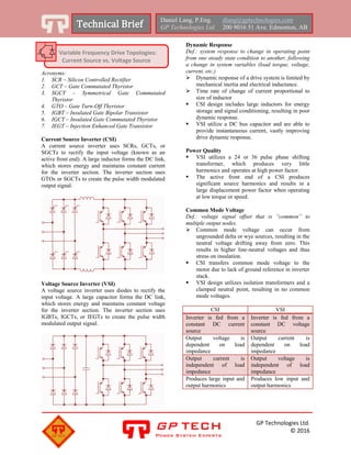
  • 1. GP Technologies Ltd. © 2016 Daniel Lang, P.Eng. dlang@gptechnologies.com GP Technologies Ltd. 200 9016 51 Ave. Edmonton, AB GP TECH Power System Experts Acronyms: 1. SCR – Silicon Controlled Rectifier 2. GCT – Gate Commutated Thyristor 3. SGCT – Symmetrical Gate Commutated Thyristor 4. GTO – Gate Turn-Off Thyristor 5. IGBT – Insulated Gate Bipolar Transistor 6. IGCT – Insulated Gate Commutated Thyristor 7. IEGT – Injection Enhanced Gate Transistor Current Source Inverter (CSI) A current source inverter uses SCRs, GCTs, or SGCTs to rectify the input voltage (known as an active front end). A large inductor forms the DC link, which stores energy and maintains constant current for the inverter section. The inverter section uses GTOs or SGCTs to create the pulse width modulated output signal. Voltage Source Inverter (VSI) A voltage source inverter uses diodes to rectify the input voltage. A large capacitor forms the DC link, which stores energy and maintains constant voltage for the inverter section. The inverter section uses IGBTs, IGCTs, or IEGTs to create the pulse width modulated output signal. Dynamic Response Def.: system response to change in operating point from one steady state condition to another, following a change in system variables (load torque, voltage, current, etc.)  Dynamic response of a drive system is limited by mechanical inertia and electrical inductance.  Time rate of change of current proportional to size of inductor  CSI design includes large inductors for energy storage and signal conditioning, resulting in poor dynamic response.  VSI utilize a DC bus capacitor and are able to provide instantaneous current, vastly improving drive dynamic response. Power Quality  VSI utilizes a 24 or 36 pulse phase shifting transformer, which produces very little harmonics and operates at high power factor.  The active front end of a CSI produces significant source harmonics and results in a large displacement power factor when operating at low torque or speed. Common Mode Voltage Def.: voltage signal offset that is “common” to multiple output nodes.  Common mode voltage can occur from ungrounded delta or wye sources, resulting in the neutral voltage drifting away from zero. This results in higher line-neutral voltages and thus stress on insulation.  CSI transfers common mode voltage to the motor due to lack of ground reference in inverter stack.  VSI design utilizes isolation transformers and a clamped neutral point, resulting in no common mode voltages. CSI VSI Inverter is fed from a constant DC current source Inverter is fed from a constant DC voltage source Output voltage is dependent on load impedance Output current is dependent on load impedance Output current is independent of load impedance Output voltage is independent of load impedance Produces large input and output harmonics Produces low input and output harmonics Variable Frequency Drive Topologies: Current Source vs. Voltage Source