2. CONTENT
1. Background
1.1. Project Introduction
1.2. Equipment Involved
1.2.1. Computer Vision System
1.2.2. Dynamixel RX64 and EX106 Servo Motors
1.3. Design brainstorming
1.3.1. Hardware
1.3.1.1. SCARA Robot
1.3.1.2. R4 Robot
1.3.1.3. Cartesian Robot
1.3.2. Software
2. Implementation
2.1. Initial Concept
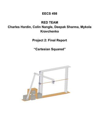
2.2. Robot Design and Construction
2.3. Design Considerations
2.3.1. Sources of Error
2.3.2. Reevaluation and Modifications
2.4. Motion Algorithm
2.4.1. Robot
2.4.2. Manual Controller
2.4.3. Autonomous Controller
3. Expected Performance
3.1. Modelling Software
3.2. Calibration and Modification
4. Results
4.1. PDay Results
4.2. Observations
5. Discussion
5.1. Discussion of Other Teams
5.2. Reflection on Current Design
5.2.1. Mechanical Design
5.2.2. Software
5.3. Future Modifications
5.3.1. Mechanical Design
5.3.2. Software
6. References
7. Appendix
3.
1. Background
1.1. Project Introduction
Our task was to build a robot arm which is capable of drawing on a piece
of paper within a 1 ft.³ workspace. There were several paper positions and
orientations, which were not known in advance except for the following
properties:
(1) the paper is a standard sheet of letter paper, laid on a rigid backing,
entirely within the workspace;
(2) the paper must face upwards or at most 5° downwards.
(3) the paper must face within 90° of a designated “front” direction.
Before attempting to draw on each orientation, our team was allowed to calibrate the robot by
hand, by moving it to known points on the paper. We were required to draw a four by four inch
square, with sides parallel to the edges of the paper. In addition, the instructor provided a sequence
of pen strokes as a list of twodimensional positions relative to the corner of the page. The robot arm
had to also draw these pen strokes on the page.
1.2. Equipment Involved
1.2.1. Computer System
The robot was controlled via a JoyApp written in python and running on a linux machine. The
computer communicated with the robot via RS485 serial connection.
1.2.2. Dynamixel RX64 and MX64 Servo Motors
Servo motors were provided along with the python library. These motors allowed both constant
rotation and joint mode operations, where prescribed torque between 1 to +1 or prescribed angles
between 10000 to 10000 could be specified. Maximum of 6 servo motors (a combination of RX64
and MX motors) were allowed in any suitable configuration.
1.3. Design brainstorming
1.3.1. Hardware
Group brainstorming meetings focused on designing a robot with simplified inverse kinematics.
As a team we came up 3 designs satisfying the design constraints of this problem. These robot ideas
are as follows:
1.3.1.1. Scara (the competition) Robot
The scara (Selective Compliance Assembly Robot Arm) is an RRRPR style robot arm that is
typically used in industrial robotics. The arm is rigid in the z axis and pliable in the XY axes. In order
17.
4.4. Discussion
4.4.1. Mechanical Design
One area where our mechanical design could be improved, is in the x direction lever arm. The
current lever arm made out of foam core was only connected by a single bolt, and therefore not very
rigid. The joint had a lot of give, and for a given x position of the end effector there was a range of x
servo angles (up to several degrees) that would result in the same x position. Therefore small
changes in the angle of the x position servo did not result in any motion of the end effector. This
limited the precision of the end effector in the x direction. If we improved the joint by adding additional
bolts and adding more foam core layers to the joint to increase the grip the bolts would have.
Additionally the location of the servo itself could be optimized. In the current configuration the
linkage arms are much longer than strictly needed to provide a full range of motion on the x axis. This
is due to the servo being mounted so low, relative to the cartesian frame and top of the pivot servo.
By raising the height of the servo, the length of that linkage could be greatly reduced, thereby
reducing the effects of servo error on x coordinate position.
The inner and outer guides for the slider support rod were an adhoc construction that could be
greatly improved upon. Gross manufacturing defects in these pieces led to uneven vertical motion of
the slider support rod. Vertical motion could also be aided by using a screw with a lower pitch. The
lead screw we used required 20 revolutions per inch of displacement. This made a painfully slow
robot and made it difficult to track vertical movement, as the servos needed to be run at full speed.
4.4.2. Software
Our software had features which were underdeveloped and thus not used at PDay. This
prevented us from trying the stroke challenge even though we had written software for it. Our
correction efforts worked well in keeping our straight lines drawn, but we could have done more to
mitigate and predict the effect of applied pressure on the pen from a software perspective. Reducing
the speed of the servo motion had a very good effect on the response to the midi board, and no
additional filtering should be necessary.
There is much more work needed to be done on the software. Stroke following should be
better tested. The framework has been made, but since drawing a square was the main requirement
of the robot, a lot of effort was spent in making sure that it would draw a square, and not much on the
following of arbitrary points. Much more testing should be done to make sure that the proposed
function in RedArmDriver.py will go between poits. The inverse kinematics function must also be
implemented to convert between paper coordinates and robot arm angles. It was deemed
unnecessary for the drawing of the square as we could hardcode the four corners in the xy robot
plane and orient our robot accordingly.
The moveTogether function in the driver file has shown good diagonal motion in testing, so
fully testing that with added pen pressure and creating an additional function to read the vector of