
Recommended
More Related Content
What's hot
What's hot (20)
Similar to Mammography
Similar to Mammography (20)
Recently uploaded
Recently uploaded (20)
Mammography
- 1. Mammography
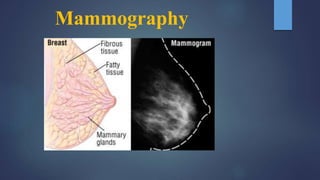
- 2. INTRODUCTION Breast imaging modalities available are Ultrasound, CT, Digital Mammography ,MRI and scintimammography . Mammography remains the cornerstone of breast imaging . Only mammography when correctly performed and interpreted offers the necessary reliability to diagnose the curable forms of breast cancers. Ultrasound, MRI , CT are useful adjuncts once a lesion has been detected by physical examination or by radiographic mammography.
- 6. INDICATIONS SCREENING Screening of asymptomatic women (40 to 44 baseline annual screening ,45 to 54 annually, 55 and older every 2 years, Screening of high risk women Follow up of patients after mastectomy of same and opposite breast. DIAGNOSTIC C/O swelling, tenderness, mastalgia, Investigations of benign breast diseases with eczematous skin, nipple discharge , skin thickening . Investigation of a breast lump Investigation of occult primary with secondary's . Male breast evaluation .
- 7. POSITIONING TERMINOLOGY: Breast Axis: Saggital plane: Transverse plane: Breast axis Axial plane Attachment to chest wall 7
- 8. Contd… Transverse plane Breast is divided into 4 quadrants 8
- 9. PATIENT PREPARATION: Explanation of procedure to the patient. The patient should be asked to change into hospital gown Should be instructed not to put on talcum powder/ /deodorant/antiperspirant/lotion under arms or on breasts on the day of mammogram as can mimic calcium spots. 9
- 10. VIEWS BASIC VIEWS: A. Cranio-caudal view. B. Medio-lateral oblique view. SUPPLEMENTARY VIEWS: A. 90 degree lateral (Medio-lateral/Latero-medial) B. Axilla C. Extended cranio-caudal (Lateral /Medial orientation) D. Caudo-cranial / reverse cranio -caudal E. Rotated cranio-caudal/ roll view F. Oblique position / latero-medial projection G. Cleavage view H. Tangential I. Spot compression J. Magnification 10
- 11. cc The casette is placed under the breast at the level of the inframammary fold . The breast is then pulled until the inframammary fold is taut . Compression applied Xray beam is directed vertically from above . Postero medial aspect included . MLO Best view to image all of the breast tissue and the pectoral muscle . The C-arm of the mammographic unit is rotated to 45 degree so that the cassette is parallel to the pectoral muscle . The film holder is kept high up in the axillary fossa and the patients arm is abducted at the elbow by 80degrees. The x-ray beam enters the breast from the medial side – compression is applied to the pectoralis major muscle .
- 14. 90° lateral Demonstrate exact location of a breast lesion If abnormality seen in MLO but not in CC to demonstrate whether this is due to artifact or superimposed tissue or it’s a true lesion Higher on lateral than MLO, then the lesion is in the medial aspect Lower on lateral than MLO then the lesion is in the lateral aspect Close to the same level on both views then the lesions is in central aspects ML (mediolateral) for lesions located in the lateral breast LM (lateral medial) Demonstrates milk of calcium, owing to its gravity dependency is best for evaluating medial lesions
- 15. Exaggerated craniocaudal Exaggerated craniocaudal (XCCL) Show lesions in outer quadrant, axillary tail and axilla, not seen on CC view Extended CC /medial orientation (XXCM) Demonstrating lesions in the medial portion of the breast The maximum inclusion of the medio-posterior part of the breast is demonstrated. (XXCL)
- 16. Roll view Used to separate superimposed breast tissue, with either lateral or medial orientation. Two exposure are often required with breast rolled in RL – counter clockwise ,RM- clockwise of R breast RM (rolled medial) Verify true lesions RL (rolled lateral) Determine location of lesion seen in one view by seeing how location changes
- 17. Tangential (TAN) Verify skin lesions, to locate skin calcification or lesions considered to be near skin for palpable lesions that are obscured by surrounding dense glandular tissue on mammogram. Cleavage view Show lesions deep in posteromedial breast not seen in CC view To view postero-medial portion of both breasts
- 18. Axillary view also known as a "Cleopatra view” Valuable in women where lymph gland involvement of a breast carcinoma is suspected or there is accessory breast tissue. Demonstrate of entire axillary tail (separation of parenchyma from thoracic wall indicates that all of axillary has been shown). Lateromedial oblique (LMO) Improved visualization of superomedial tissue Improved tissue visualization and comfort for women with pectus excavatum, recent sternotomy, prominent pacemaker
- 19. Caudo-cranial /Reverse cranio-caudal Reverse CC may be helpful when Pt is small , or a muscular male. Improved resolution is needed for the suspicious area in superior or the upper quadrant of breast. Patient is dyphotic, has a pacemaker. Needle localization is performed on an inferior lesion.
- 20. Spot compression Determine whether lesion is real or is a summation shadow Spot compression with magnification (M) Better definition of margins of masses and morphology of calcifications to evaluate and count micro-calcifications and its extension requires magnification platform to separate the compressed breast from the cassette 1.5 to 2 time magnification obtained by increasing the object-film distance, producing an `air gap',
- 21. Imaging is similar to that of a small female breast.
- 22. GALACTOGRAPHY (DUCTOGRAPHY) Also called contrast mammography ductography as the study includes the injection of contrast material into a duct. There is 10% incidence of carcinoma in women operated upon for nipple discharge. It is done for evaluation of spontaneous nipple discharge that is bloody, serous or clear in nature originating from one or two ducts. 22
- 23. PROCEDURE Clean the nipple with cleansing agent & betadine is applied. Needle is inserted under aseptic conditions into the orifice of discharging duct. C/M is injected about 1-3 ml. Immediate radiographs are taken in cranio - caudal and medio - lateral oblique positions. Heavy compression is not applied because c/m will ooze out due to pressure. So light compression is given. 23
- 25. Mass A 'Mass' is a space occupying 3D lesion seen in two different projections. If a potential mass is seen in only a single projection it should be called a 'asymmetry' until its three-dimensionality is confirmed.
- 27. Calcifications Calcifications are either typically benign or of suspicious morphology.
- 30. BI-RADS assessment categories can be summarized as follows : Category 0 - Need additional imaging evaluation Category 1 - Negative Category 2 - Benign finding, noncancerous Category 3 - Probably benign finding, short-interval follow-up suggested Category 4 - Suspicious abnormality, biopsy considered Category 5 - Highly suggestive of malignancy, appropriate action needed Category 6 - Known cancer, appropriate action should be taken
- 31. Principles Of Breast Cancer Patients in the early stages respond well to extensive surgery Patients with advanced disease do poorly The earlier the diagnosis, the better the chance of survival Mammography is the tool for early detection Incidence increases with age More sensitive to carcinogens during menarche Women with positive family members are more prone to breast cancer
- 32. MQSA Mammography Quality Standards Act Mandated the following: Formal training and continuing education Required regular inspection of equipment Documentation of quality assurance Report means of reporting results, follow-up, tracking patients, and monitoring outcomes
- 34. MAMMOGRAPHY EQUIPMENT designed to image the soft tissue of the breast while displaying the necessary subtle contrast differences. High frequency generators Cathode – dual filament in focusing cup with focal spot size 0.3-0.4 and 0.1-0.15 mm (for magnification) Anode - rotating ,SID – 65cm low operating voltage - below 40 kV, Target – (Mo), (Rh) (W) Beryllium window – Minimizes absorption of radiation within the tube . Filter – Mo/Mo, Mo/Rh , Rh/Rh , W/Rh , W/Ag Compression device : 1-4 mm thick plastic plate
- 35. Anode design rotating anode Characteristics X-ray production is the major reason for choosing Mo (K-shell x-ray energies of 17.5 and 19.6 keV) and Rh (20.2 and 22.7 keV) as targets. With tungsten targets, Bremsstrahlung x-rays will predominate at energies above and below the 17-24 keV range. Although tungsten emits “harder” spectrum rays, the wider dynamic range can be utilized in digital imaging. requires the effective anode angle to be at least 20º to avoid field cutoff for the 24 x 30 cm field area Combination of anode angle and tube tilt used
- 37. Compression Device manual, hand-controlled compression device, controlled by the mammographer. The effects of compression are: reduced dose; reduced scatter- improved contrast; less geometric unsharpness; low movement unsharpness; uniform breast thickness; reduced tissue overlap improved resolution. Amount of compression – 25- 45 lbs pounds of pressure (111-200N) may be uncomfortable for the patient
- 39. GRID Grid is used to reduce the scatter radiation reaching to the film Most system have moving grid with a ratio of 4:1 to 5:1 . Grid frequency» 40 lines/cm. Specially HTC grid is used in mammography. cellular grid, made of thin copper septa, provides scatter rejection in two dimensions . Specifications of this design include a septal height of 2.4 mm, 0.64-mm distance between septa (3.8 ratio), a septal thickness of 0.03 mm, and 15 cells/cm
- 41. Heel effect Lower x-ray intensity on the anode side of the field at short SID Positioning the cathode over the chest wall of the patient and the anode over the nipple achieves better uniformity of the radiation transmitted through the breast Orientation of the tube in this fashion also decreases the equipment bulk near the patient’s head for easier positioning
- 43. Focal spot considerations Focal spot sizes range from 0.3 to 0.4 mm for non magnification and from 0.1 to 0.15 mm for magnification imaging Focal spot and central axis are positioned over the chest wall at the image receptor edge A reference axis, which typically bisects the field, is used to specify the projected focal spot size
- 45. Beam quality considerations The optimal x-ray energy to achieve high subject contrast and the lowest radiation dose would be a monoenergetic beam of 15 to 25 keV, depending on breast composition and thickness Screen-film detectors most often use a Mo target and 0.03-mm Mo filtration with a kV of 24 to 25 kV for thin, fatty breasts and up to 30 kV for thick, glandular breasts. For thicker and denser breasts, a Mo target and Rh filter are selected with higher voltage, from 28 to 32 kV, to achieve a higher effective energy and more penetrating beam We need relatively low penetration to enhance contrast but high penetration is needed to reduce the dose to the breast. The solution is to use an x-ray beam that has a spectrum that produces an optimum balance between the requirements for high contrast sensitivity and low radiation dose.
- 46. Beam Filtration Filtration is defined by the half-value layer (HVL). In mammography added filtration shapes the emission spectrums of the x-ray beam and makes it compatible with the image receptor and breast characteristics of each patient. Filtration will also improve the energy-distribution x-ray spectrum by selectively removing the very low energies and higher energies outside of the desired range. In digital imaging, filtration will also help to reduce exposure time, eliminating potential motion artifacts. Minimum HVL is specified by regulations and should not measure less than 0.30 mm Al at 30 kVp or 0.25 mm at 25 kVp to ensure that the patient will not receive excessive radiation dose. The HVL also should not exceed 0.40 mm Al at 30 kVp to avoid excessive filtration that would reduce contrast by filtering out the low-energy photons necessary to penetrate the breast tissue. Any HVL assessment must include an assessment of both the inherent and added filtration.
- 47. Filtration Inherent filter- require beryllium (Z = 4) to permit the transmission of low energy x-rays. Added filter - thin filters of Mo, Rh, and silver (Ag) used to transmit bremsstrahlung x-rays in the intermediate energy range (15 to 25 keV), including characteristic radiation from Mo and Rh, and also to highly attenuate lowest and highest x-ray energies in the spectrum The filters used in mammography are based on the "k edge" principle and attenuate or block the radiation above the k-edge energy of the specific filter material
- 53. Collimation For most mammography examinations, the field size matches the film cassette sizes (e.g., 18 x 24 cm or 24 x 30 cm) Variable shutters on some systems allow the x-ray field to be more closely matched to the breast volume In practice, the large unexposed area of the film from the tight collimation allows a large fraction of light transmission adjacent to the breast anatomy on a light box, and can result in poor viewing conditions X ray beam is collimated by means of cone which produces D- shaped field.
- 54. Generator & phototimer(AEC) High-frequency generators are the standard for mammography systems Unlike most conventional x-ray units, the AEC detector is located underneath the cassette Phototimer algorithms take into account the radiographic technique (kVp, target/filter) and, in the case of extended exposure times, reciprocity law failure, to achieve the desired film optical density Fully automatic AEC sets the optimal kV and filtration from a short test exposure of ~100 msec TWO TYPES : (i)Ionization chamber type (ii) Solid state diode type
- 56. Screen-Film Systems Mammography cassettes contain a single screen The film is single emulsion Occasionally, extended time processing is used This reduces dose and increases contrast
- 57. Screen-Film cassettes used in Mammography
- 58. Magnification referred to as macro radiography Mammo only modality that routinely uses magnification views Use a raised platform to support the breast about half way between focus and film i.e. not in close(ish) contact anymore Magnification is the result of the diverging X-ray beams travelling in straight lines
- 59. Magnification imaging Magnifies image by a factor of between 1.5-1.8 Magnification increases geometric unsharpness so small focal spot is used Increases exposure times due to lower mA Can remove grid to lower exposure factors (and patient dose) as scatter is reduced by the air gap Overall patient dose is higher Magnification requires individual justification
- 61. Physics of full field digital mammography (FFDM)
- 62. FFDM Differences Image acquisition and display are separated Wide dynamic range Lower Dose (~20%) Same dose limits as for film-screen Higher kVp (+3 kVp) Better for dense breasts Imaging detector can be used as AEC detector Use of Mo/Mo, Mo/Rh, Rh/Rh, W/Rh and W/Ag targets For CR, the film-screen cassette is replaced with a photostimulable phosphor plate cassette
- 63. FFDM Differences Digital images Require workstations Post-processing image enhancement Computer aided diagnosis Archival issues (>9 Mbyte/image)
- 64. AEC is different Done with the image detector rather than discrete radiation detectors. System can automatically select the densest aspect of the breast for AEC “cell” positioning or the technologist can manually select the AEC “cell” position
- 65. Digital mammography detectors X-ray to digital information. “DIRECT” conversion - Amorphous selenium (direct conversion) using (TFT) flat panel technology ~70 micron pixels “INDIRECT” conversion - Scintillating phosphor (CsI columns) on an array of amorphous silicon photodiodes using thin-film transistor (TFT) flat panel technology ~100 micron pixels
- 66. Independent (“Indirect”) Conversion: Blocking Layer CsI X-Ray Photons Light Photodiode Photodiode Electrons Read Out Electronics X-ray Digital Data 2,600+ Volts Electrode Dielectric Digital Data Electrons X-Ray Photons Selenium K-edge Fluoresence Electrons Read Out Electronics X-ray Electrode Capacitor Dependent (“Direct”) Conversion: Detector Technology Overview Courtesy: Jill Spear, GE Women’s Healthcare
- 67. Does pixel size matter? As pixel size decreases: Spatial resolution improves Noise increase Signal-to-noise decreases
- 68. Computed Radiography for Digital mammography
- 69. Digital Mammography Detector is a flexible plastic coated with photostimulable x-ray absorbing phosphor material. The electronic charges are stored in “traps” in the material of phosphor. The image is then read by scanning of imaging plate by a laser beam. The resulting signal is logarithmically amplified,digitized and processed for film or soft copy display. The imaging plate is erased by exposure to white light.
- 70. Mean glandular dose The mean glandular dose (MGD) is an estimate of the average absorbed dose to the glandular tissues of a breast during mammography. It is measured in Gray (Gy). MGD = Kgds K = entrant surface air kerma g = conversion factor for 50% glandular breast based on thickness and half-value layer c = correction factor based on non-standard glandularity/thickness s = correction factor based on non-molybdenum anode/filter combination standard breast (defined as 4.2 cm thick when compressed, with a 50:50 ratio of glandular tissue to fat), the MGD is typically 2 mGy per view. For full-field digital mammography systems, the dose is lower, typically from 1.2 to 1.8 mGy per view.
- 72. Contrast Enhanced Digital Mammography CEDM is a recent development of digital mammography using the intra-venous injection of an iodinated contrast agent in conjunction with a mammography examination. is being used sparsely for cancer staging or neoadjuvant follow-up in places where MRI may not be available. This technique can increase mammographic lesion conspicuity.
- 73. Two techniques have been developed to perform CEDM examinations – 1. Temporal Subtraction : Done by acquisition of high-energy images before and after contrast medium injection. The temporal subtraction technique offers the possibility to analyze the kinetic curve of enhancement of breast lesions. Dual-energy takes advantage of the difference in the atomic density of tissue, as compared to the contrast. Two images are acquired, and the low- density breast tissue is subtracted; however, the high energy of contrast persists, allowing any enhancing abnormality to be more visible. The main disadvantages of this technique are that only a single breast can be imaged and patients have to maintain a particular position (usually MLO) for a prolonged period Prone to Motion artifacts
- 74. 2. Dual Energy CEDM technique based on dual-energy acquisitions, where two images are acquired using distinct low-energy (standard mammography kV and filtration) and high-energy (higher kV with strong filtration) X-ray spectra. The differences between X-ray attenuation of iodine and breast tissues at these two energy levels are exploited to suppress the background breast tissue. Dual-energy CEDM depicts areas in the breast associated with increased vascularity 2 min after the start of contrast injection that images are acquired.
- 75. Post-contrast images show an enhancing lesion infero-medial quadrant - DCC Post contrast images show an enhancing lesion proved to be malignant on biopsy
- 77. Breast Tomosynthesis Also known as 3D mammography. Its an extension of digital mammography Breast tomosynthesis is a new tool that is based on the acquisition of three- dimensional digital image data, could help solve the problem of interpreting mammographic features produced by tissue overlap. In breast tomosynthesis, a moving x-ray source and a digital detector are used.
- 78. The x-ray tube in a breast tomosynthesis system moves along an arc during exposure. An arc like linear motion is suitable for imaging of breast tissue because most normal anatomic structures in the breast are oriented from the chest wall to the nipple. A wider angular range allows a thinner reconstructed section thickness of the in-focus plane because objects in the different planes are less blurred on images acquired at a smaller angle.
- 79. Normal glandular tissues are more clearly depicted on the breast tomosynthesis image (arrows in a) than on the digital mammogram (b). Normal lactiferous ducts are more prominently depicted on the breast tomosynthesis image (arrows in a) than on the digital mammogram (b).
- 80. Advantages it has the same advantages as that of FFDM. Better depiction of the smallest calcifications, better delineation of the lesion border requires less compression than 2D mammography. Disadvantages Motion artifacts are more likely to occur Large calcifications cause significant artifacts.
- 81. Computerized Tomography Laser Mammography Is an optical tomographic technique for breast imaging. uses laser energy in the near infrared region of the spectrum, to detect angiogenesis in the breast tissue It is optical molecular imaging for hemoglobin both oxygenated and deoxygenated. laser beams travel through tissue and suffer attenuation then a laser detector measures the intensity drop and the data is collected as the laser detector moves across the breast creating a tomography image. is able to recognize malignant tumor from benign lesion And shows hemoglobin distribution in a tissue , detect areas of Angiogenesis
- 83. Scintimammography Scintimammography, also known as nuclear medicine breast imaging, (Breast Specific Gamma Imaging (BSGI) or Molecular Breast Imaging (MBI). Done in those who had abnormal mammograms, or for those who have dense breast tissue, postoperative scar tissue or breast implants. Patient receives an injection of a small amount of a radioactive substance called technetium 99 sestamibi, which is taken up by cancer cells, and a gamma camera is used to take pictures of the breasts. The procedure is less accurate in evaluating abnormalities smaller than one centimeter. Patient is exposed to slightly more radiation than mammography but has higher sensitivity and positive predictive value than conventional mammography.
- 84. Optical Mammography Diffuse optical imaging is a set of non-invasive imaging modalities that use near- infrared light then applies an algorithm to interpret the image and information. The technique can measure differences in water and fats. The tool creates real-time images of metabolic changes, allowing the differentiation between oxygen rich and oxygen-poor tissue and varying levels of hemoglobin through differences in light absorption. comparatively more comfortable with much less breast compression compared to conventional mammography.
- 86. Computer Aided Detection Mammography has a low positive predictive value of 35% in detection of malignancies. But, due to the high number of mammograms to be read, the accuracy rate tends to decrease CAD can assist the medical staff to achieve high efficiency and effectiveness, thereby reducing the false positive rate. It is a two level reporting system thus helps to reduce interpretative or subjective errors. studies have shown the ability of CAD to mark cancers with a high degree of accuracy, especially when microcalcifications are present
- 88. Positron Emission Mammography PEM has higher resolution and a more localized field of view ,performed on patients to stage a newly diagnosed malignancy. uses a pair of dedicated gamma radiation detectors placed above and below the breast and mild breast compression to detect coincident gamma rays after administration of fluorine-18 fluorodeoxyglucose (18F-FDG) cancer cells demonstrate increased utilization of glucose. Through use of isotope fluorine-18 attached to the delivery compound deoxyglucose to produce the radiopharmaceutical 18F-FDG, this utilization of glucose can be visualized. Advantages such as better delineation of lesion, high positive predictive value for malignancies and effective in follow up or in planning for RT Has higher radiation exposure
- 89. Breast Ultrasound Breast ultrasound is an important modality in breast imaging. Use of breast ultrasound: • evaluate young (usually under 30 years of age) or pregnant patients who are symptomatic • evaluate a palpable lump with negative or equivocal mammographic findings • detect lesions in lower contrast field • help to distinguish between benign vs malignant characteristics • guiding biopsy • evaluate breast implants for rupture reasonable sensitivity but poor specificity may have a place in screening women at high risk or with mammographically-dense breasts probe: linear array 7-13 MHz
- 90. Breast MRI It is a valuable tool to diagnose additional cancer in the same breast in up to one third of patients and is recommended as a supplemental screening tool to mammography in women considered to be at high risk for developing breast cancer. MRI is more sensitive in detection of invasive lobular cancer, Dedicated bilateral breast surface coil (simultaneous examination of both breasts) Preoperative MRI more accurate in assessing tumor extent and multi-focality (incl. DCIS) MRI lowest FN rate in detecting Invasive lobular carcinoma, highest accuracy in measuring the size MRM could detect extensive intraductal component (EIC): sensitivity 71%, specificity 85%, accuracy 76%
- 91. Pitfalls MRI typically costs more and takes more time to perform than other imaging modalities. MRI persistently underestimate minimal residual disease
- 92. Electrical Impedance Scanning (EIS) used as an adjunct tool to mammography in helping to detect breast cancer. The T-scan measures low level bioelectric currents to produce real-time images of the electrical impedance properties of the breast. The resulting impedance images of the breast tissue can be used to help determine if the region of interest is normal tissue or a cancerous tumor. The T-scan works by creating an image "map" of the breast using a small electrical current. One-volt of continuous electricity (approximately the same as holding a flashlight battery by its ends) is transmitted into the body, either through an electrode patch attached to the arm or a hand-held cylinder. The electric current travels through the breast where it is then measured at skin level by a probe placed on the breast.
- 93. Mammographic equipment specification Company- Siemens healthcare Model –Simens mammomat fusion full field digital mammography X-ray tube – tungsten rotating anode tube with beryllium window P40 Anode speed – 8800rpm C-arm rotation:180 degree to -180 degree Power rating – 5kw Anode heat storage capacity – 162KHU Inherent filtration: 1mm Be (- 0.02 mm Al) Focus size – 0.3 , 0.15 Detector type – CSI Detector size – 23* 30 cm Anode material – W , Filter – 50 micro m Rh
- 94. Grid ratio – 5:1 , linear grid Grid density – 31 lines/cm Kv range – 25kv – 35kv (adjustable in 1 kv increments) mAs – 5mAs to 600mAs AEC mode Time range – 10ms-4s with large focus, 60ms to 6s with small focus mA range – 20 to 190 mA Collimation – automatic Magnification compression plate – 16*20cm Spot compression plate – 9*9cm SID – 65cm Weight – max 350kg
- 95. REFERENCES The essential physics of medical imaging by Bushberg Radiologic science for technologist by Bushong Chesney’s equipment for student radiographer Websites