Call Girls In {Laxmi Nagar Delhi} 9667938988 Indian Russian High Profile Girl...
Alarms_grouping_Current_Alarms.pdf
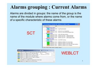
1. Alarms grouping : Current Alarms
Alarms are divided in groups: the name of the group is the
name of the module where alarms come from, or the name
of a specific characteristic of these alarms
SCT
SCT
WEBLCT
ALplus2/ALCplus2 1
2. Alarms groups : COMMON
Alarms related to Controller module and EOC channel.
ALplus2/ALCplus2 2
3. Alarms groups : COMMON
•
Alarm Causes Alarms that could have generated the
alarm
Equip. Man Op Manual operation active
Equip. Man Op Manual operation active
(check list)
Rmon (Remote Monitoring) Statistic counter Ethernet
C 2Mb/ EOC D t Li k T ib ith EOC i i i EOC t ib LOS
Comm. 2Mb/s EOC Data Link Trib with EOC is missing EOC trib LOS
2Mb/s G704 Line Side AIS Trib with EOC has AIS
2Mb/s G704 Line Side Fail Trib with EOC is missing EOC trib LOS
2Mb/s G704 Line Side Fail Trib with EOC is missing EOC trib LOS
2Mb/s G704 Radio Side AIS Trib with EOC has AIS
from remote
2Mb/s G704 Radio Side Fail Trib with EOC is missing
from remote
EOC trib LOS
Comm. Radio EOC Data Link Link EOC is missing Link ID
Controller waiting for restore Configuration mismatch
(download backup)
Lan Cable Fail EOC LAN cable missing
ALplus2/ALCplus2 3
g
5. Communication EOC [E1/STM1] Data link
No EOC channel is present
on selected tributary in
on selected tributary in
selected timeslot : wrong
port address configuration
p g
or no tributary input
(LOS).EOC is the channel
involved in management
involved in management
communication.
If EOC 2Mb link is active:
If EOC 2Mb link is active:
- Management is cut (no
remote)
- If relative LOS is active,
traffic on that tributary is
out
ALplus2/ALCplus2 5
out
6. 2Mb/s G.704 (Trib.x)
R di F il/AIS d/ Li F il/AIS
Radio Fail/AIS and/or Line Fail/AIS
When management
When management
messages come via
tributary timeslot,
f h h k
further checks are
performed on both
directions of used
directions of used
tributary
To clear the alarm, set :
2Mb selector = 0
Slot Selector = 0
ALplus2/ALCplus2 6
7. Communication Radio EOC Data link
No link between Local and Remote station or wrong port address
configuration.
g
EOC is the channel involved in management communication.
If EOC radio link is active:
If EOC radio link is active:
- Traffic is OK
- Management is cut (no remote)
ALplus2/ALCplus2 7
8. Equipment controller waiting for
fi ti d t t
configuration data restore
Press Here
When MCU is been replaced
ALplus2/ALCplus2 8
9. Alarms groups: ETH LAN
Alarms (internal and external) regarding Ethernet traffic and
relevant ports.
p
ALplus2/ALCplus2 9
10. Alarms groups: ETH
•
Alarm Causes
Link loss Loss of Ethernet signal
Sync Gigabit frame not aligned
Sync Gigabit frame not aligned
Auto Negotiation Auto negotiation failed
Link loss forwarding Link loss in remote ports
ALplus2/ALCplus2 10
11. Alarms groups: LIM
Alarms coming from LIM failure or from:
• Tx direction - external failure (tributary LOS)
• Rx direction - alarms in previous module (RIM, ODU) or
external failure (bad propagation or remote alarmed or no
remote)
remote)
ALplus2/ALCplus2 11
12. Alarms groups: LIM
•
Alarm Causes
Trib Signal Loss Enabled trib missing or disabled trib present
g g p
Trib AIS AIS present in input
Modulator Fail Modulator fail or without/low quality input
D d l F il D d l f il i h /l li i
Demodulator Fail Demodulator fail or without/low quality input
ODU-IDU communication fail Signal from ODU missing
ALplus2/ALCplus2 12
13. Tributary-1 Signal loss
Loss Of Signal alarm is active when a situation opposite to that
foreseen by configuration is performed on tributary interface:
No input or
o pu o
cable
disconnected
ALplus2/ALCplus2 13
14. Branch-x Modulator/Demodulator Fail
This alarm is active when the Modulator / Demodulator not
transmit / receive the data signal.
g
Demodulator fail can be when the remote radio is power OFF
Traffic is cut
Traffic is cut
ALplus2/ALCplus2 14
15. Branch-x ODU-IDU Communication
fail
This alarm occurs when on carrier used to receive
information from ODU, or remote commands from other side,
are detected:
are detected:
CRC errors
Loss of frame
This carrier is separated from carrier used for opposite
direction (IDUODU) and from TX or RX carriers
( )
ALplus2/ALCplus2 15
16. Alarms groups: NODE
Al l t th ti b t th IDU i th
Alarm relevant the connections between the IDUs composing the
node.
Alarm Causes
Los NBUS cable missing
Lof FAW not recognized
MsAis MsAIS in NBUS frame payload
Check Wrong NBUS connection order between IDUs
ALplus2/ALCplus2 16
Check Wrong NBUS connection order between IDUs
17. Node (1 or 2) Signal Loss Alarm
NBUS cable, connecting different Nodal IDU of the same node,
is missing. IF IDU is a “no Nodal” unit, alarm is disabled. NBUS
cable F03471* despite RJ45 connector is not an Ethernet cable
cable F03471 , despite RJ45 connector, is not an Ethernet cable
Node (1 or 2) Signal Lof Alarm
Node ( o ) S g a o a
The FAW, Frame Alignement Word in the signal on NBUS
connection, has not been recognized
connection, has not been recognized
Node (1 or 2) MsAIS Alarm
( )
The payload in the frames of the signal in NBUS connection
does not contain the 126 E1 streams but AIS signal: a LOS or
g
LOF alarm is present in another NBUS connection.
(Not active at the moment)
ALplus2/ALCplus2 17
*Siae code
( )
18. Node (1 or 2) Check Alarm
The Nodal IDUs connected through NBUS cable don’t have the
same Identifier. Identifier is not modificable by the user
IDU 1 NB1 NB2
LAN 1 LAN2
From LAN 1 of IDU8 From NB1 of IDU8
IDU 2 NB1 NB2
LAN 1 LAN2
IDU 3 NB1 NB2
Max 8 LAN 1 LAN2
Max 8
. . . . . . . . .
IDU 8 NB1 NB2
LAN 1 LAN2
To LAN 2 of IDU1 To NB2 of IDU1
ALplus2/ALCplus2 18
To LAN 2 of IDU1 To NB2 of IDU1
19. Alarms groups: P.M. (Performance Monitoring)
Alarms regarding all measurements performed in Performance
Monitoring section.
Performance Monitoring Description
G828 radio Quality measurements on on signal radio
received
G828 LimA E1 line side Quality measurements on E1 line side
G828 LimA E1 radio side Quality measurements on E1 radio side
Rx Pwr radio Rx power measurements
Tx Pwr radio Tx power measurements
ACM radio Radio Modulation Monitoring
g
G829 RST B1 Quality measurements on RST (STM1)
G829 MST B2 M1 Quality measurements on MST (STM1)
ALplus2/ALCplus2 19
G829 MST B2 M1 Quality measurements on MST (STM1)
G829 RST B1 Quality measurements on Vc12 (STM1)
20. Alarms groups: Plug-in module
Alarms relevant the plug-in modules used for STM-1 lines.
ALplus2/ALCplus2 20
22. Alarms groups: RADIO
• Alarm Causes Alarms that could have
generated the alarm
Alarm generated
Link ID Wrong ID received Link Telemetry Fail
Link ID Wrong ID received Link Telemetry Fail
Link Telemetry
Fail
Radio link missing Link ID Comm, radio EOC
data link
Revertive Radio link working on reserve
branch
Alarms of the preferential
branch
Tx Fail Tx switch on remote Ber
PRBS Fail PRBS not receiving
Reduced
C i
Degraded radio link capacity
(A l T d l i ≠
Capacity (Actual Tx modulation ≠
Upper modulation)
ALplus2/ALCplus2 22
23. Link ID
Alarm is on if Link ID check is enabled (Link ID 0) and remote
Link ID is different from the local one.
Traffic is cut but signal is received and measured.
Thi l
This alarm
causes:
- Traffic is cut
Traffic is cut
- OK Management
ALplus2/ALCplus2 23
24. Link telemetry fail
No link between Local and Remote station. Traffic is cut.
Link telemetry is inserted in main radio frame in Bit Insertion
y
circuit inside LIM, and contains commands for the remote
station: switch off the radios on remote side in case of local RF
loop Link ID ATPC info
loop, Link ID, ATPC info.
Telemetry link is a connection between local and remote IDUs.
TEST - if this alarm occurs, a double IDU loop (both branches)
can be done: if this alarm disappears, local IDU is OK and the
problem is after (propagation local radios remote equipment)
problem is after (propagation, local radios, remote equipment).
ALplus2/ALCplus2 24
25. Revertive
When a branch is
d l d f ti l
declared preferential,
the switch on opposite
branch gives Revertive
b a c g es e e e
alarm.
The return to
preferential branch,
when available again,
happens after “Wait
happens after Wait
Time” period or press
Reset.
ALplus2/ALCplus2 25
26. Tx Fail
When on remote side both radios don’t receive, on local side a
Tx switch command is performed and Tx fail alarm is enabled.
When this alarm is on,
check local ODU in stand by
check local ODU in stand by
This functionality is enabled
in LCT – General Preset
in LCT General Preset
The alarm remains active
until Reset is given
ALplus2/ALCplus2 26
27. PRBS Fail
When PRBS is working and no signal is received on checked
i l i PRBS i d th fi ld S L Al i ti
signal, in PRBS window the field Sync Los Alarm is active
together with PRBS Fail in Current alarms window
Every ON-OFF transition
increases the field
PRBS Fail Alarm Counter
ALplus2/ALCplus2 27
28. Adaptive Modulation Reduce Capacity
N ifi i
Notification
When ACM Engine is
When ACM Engine is
enable in both radio
(L l d R t ) d
(Local and Remote) and
the Power receive is not
enough (too low)
respect the normal
condition.
ALplus2/ALCplus2 28
30. Alarms groups: RIM
• Alarm Causes Alarm generated
Power Supply 48 Vdc input missing, dc output not RF unit not
compliant responding
Cable Open IDU-ODU cable cut or not connected RF unit not
responding /
responding /
Comm. Fail
Cable Short IDU-ODU cable damaged (shortened) RF unit not
g ( )
responding /
Comm. Fail
C bl O d P l i k RF i
Cable Open and
Short
(both active)
Power supply is weak RF unit not
responding /
Comm. Fail
( )
ALplus2/ALCplus2 30
31. Branch-x Cable open/short
This alarm is active when the
following situations occur:
g
- Cable open alarm no current
through cable interface: ODU is
not supplied so situation looks
not supplied… so situation looks
like PSU alarm (Rx alarms) with
cable alarm instead PSU alarm
- Cable short alarm
overcurrent/low voltage through
cable interface
cable interface
Conseguence of Cable
open Radio1A
C bl IF O R di 1A
ALplus2/ALCplus2 31
Cable IF Open Radio1A
33. Alarms groups: RT
• Alarm Causes Alarms that could have
generated the alarm
Alarm
generated
Rx power low Rx signal lower
than Rx threshold
Remote Tx not working /
Bad propagation
LIM quality
alarms
Tx power low RT failure if Tx is Man Op (Tx Off)
Tx power low RT failure if Tx is
ON
Man Op (Tx Off),
Modulator fail
IDU-ODU RT o relevant
communication RIM damaged
RT VCO fail RT failure
IF f il RT f il if T i M O (T Off)
IF fail RT failure if Tx is
ON
Man Op (Tx Off),
Modulator Fail
Rx Quality alarm BER ≈ 10E-6
Q y
Rx Quality
warning
BER ≈ 10E-10
ALplus2/ALCplus2 33
34. RT Rx Power Low
This alarm occurs when
Rx power is under a
d fi d th h ld
defined threshold
Threshold value can be
t f b th b h i
set for both branches in
range:
40 dBm 99 dBm in
-40 dBm- 99 dBm in
LCT - General preset
The alarm Rx Power Low
Decrease this value below – 60dBm
T l th l The alarm Rx Power Low
is a branch alarm and it is
used to drive Rx switch
To clear the alarms
ALplus2/ALCplus2 34
35. RT Tx Power Low
This alarm occurs when Tx
power is 3 dB under standard
power is 3 dB under standard
output of ODU-RF unit.
ATPC or manual attenuation do
ATPC or manual attenuation do
not affect this alarm that is given
by internal failure of the radio.
This alarm can be activated by a
manual operation also: Tx
Transmitter off in Radio Branch
Transmitter off in Radio Branch
- Settings
If both Rx Power Low and Tx
If both Rx Power Low and Tx
Power Low are active, RF unit
inside ODU is faulty
ALplus2/ALCplus2 35
36. IDU-ODU Communication fail
This alarm occurs in ODU when on carrier used to
This alarm occurs in ODU when on carrier used to
receive command from IDU, are detected:
CRC errors
CRC errors
Loss of frame
Thi i i t d f i d f
This carrier is separated from carrier used for
opposite direction (ODUIDU) and from TX or RX
carriers
carriers
ALplus2/ALCplus2 36
37. RT VCO fail
This alarm occurs when VCO in RF unit is not able to
lock any frequencies.
lock any frequencies.
Every problem in VCO causes alarms in both
directions: RF unit is not able to convert IF Tx in RF
directions: RF unit is not able to convert IF Tx in RF
Tx (Tx Power Low alarm) and RF Rx in IF Rx .
ALplus2/ALCplus2 37
Possible Solution: Check and Replace cable IF
38. RT If fail
This alarm occurs when is not present IF signal inside
p g
ODU. There are two different IF signals but one alarm
only.
IF Tx: the alarm is on with Tx Power Low
IF Rx: the alarm is on with all Rx alarms
IF Rx: the alarm is on with all Rx alarms
When VCO is faulty, RF unit gives a IFRX signal made
up of noise: this is enough to mantain IF fail alarm off
up of noise: this is enough to mantain IF fail alarm off.
ALplus2/ALCplus2 38
39. RT Rx Quality Warning Alarm
RX Quality Warning
BER ≈ 10E-10
RX Quality alarm
BER ≈ 10E-6
ALplus2/ALCplus2 39
40. Alarms groups: SETS
Alarms (internal and external) relevant to the synchronism
sources and their setting.
Alarm Causes
T0Squelch T0 Synch missing
T4Squelch T4 Synch missing
FreeRunning Equipment in FreeRunning status
Holdover Equipment in Holdover status
ALplus2/ALCplus2 40
SynkLos Selected Synch missing
SynkDrift Selected Synch bad quality
41. BaseBand Sets STM1 (T0) LTI Alarm
Disconnect cables STM1, after
the duration LTI Set Time (Loss
(
Timing Input) [0..60sec], there
will be the alarm Major “SETS
STM1-WEST (T0) LTI Alarm”
STM1-WEST (T0) LTI Alarm
Reconnect cables STM1, after
the duration WTR (Wait To
(
Restore), change the status
Free Running at Locked and
after the duration LTI Reset
after the duration LTI Reset
Time (Loss Timing Input)
[0..60sec] the alarm Major
“S S S 1 S ( 0)
“SETS STM1-WEST (T0) LTI
Alarm” will be clear.
ALplus2/ALCplus2 41
42. BaseBand Sets STM1 (T0) Drift Alarm
Drift: clock frequency is out of range
BaseBand Sets T0 Fail alarm
Sync input: no synchronismous source (in input) is
available or without problem
BaseBand Sets T4 Fail alarm
BaseBand Sets T4 Fail alarm
Sync output: T4 synchronismous generation is not
il bl
available
ALplus2/ALCplus2 42
43. Alarms groups: SNTP
Alarms regarding the SNTP server.
Alarm Causes
Unicast Server Lost Server is missing
Unicast Server Lost Server is missing
ALplus2/ALCplus2 43
44. Alarms groups: STM1
Alarms (internal and external) relevant to STM1 stream, line side.
Alarm Causes Alarm generated
Los Enabled trib missing or disabled trib present
f i d
Lof FAW not recognised
B2ExcessiveBer Excessive BER
B2SignalDegraded Signal Degraded
J0TraceIdentifierMismatch J0received is not the expected one QECC alarm
MsAis AIS in Multiplexer section
MsRdi RDI in Multiplexer section
ALplus2/ALCplus2 44
p
45. Alarms grouping : UNIT
This group generates alarms when one of the units,
the equipment consists of, is faulty or does not
q p y
respond to controller polling
ALplus2/ALCplus2 45