1. 3D Printing for WFIRST-AFTA Concept Development
Catherine Peddie, 448
Jeff Stewart, 543
Engineering
Summer 2014
Christen McWithey
University of Maryland
Results: Dissolvable Material
PVA dissolvable filament was chosen initially because it would be simpler to dissolve than HIPS,
in water instead of limonene. ABS was known to work on this MakerBot, so PVA was paired with
ABS.
Other MakerBot users had success printing with PLA, but it continued to clog the extruder.
Because ABS was already known to work well in this version of MakerBot, the alternative
combination of HIPS & ABS was chosen instead of PLA & PVA.
Left: a sample ABS medallion with a majority of the PVA
material dissolved away. Center: PVA and ABS together, the
PVA (white) is coming away from the ABS (black). Right: two
colors of ABS bonded to each other.
Left: The PLA filament hardened inside the extruder, which
prevented it from finishing the print. Near Right: The clear box
could not finish printing because of the clog. Far Right: A
completed blue ABS box.
The purge walls that
are printed with the
model. The black
wall on the left fell
off the build plate
midway through the
print, which caused
the tangled ‘hair’.
ABS raft (black)
with HIPS support
material (white).
The HIPS came
away from the ABS
after a few layers
until it was
unrecoverable.
A sample part
with HIPS raft
and support. The
legs of the part
curled up and
eventually the
entire part
detached from the
plate.
Methods
1. The appropriate model was slightly modified in SolidWorks CAD software to be thick and
robust where necessary.
2. The finished part was saved as a .STL file, the only type of file format compatible with
MakerWare.
3. In MakerWare, the part was scaled from 100% to 2.99%. Originally the scale was proposed to
be 3%, but the main model was too tall for the print volume, so the scale was reduced by
0.01%.
4. The object was placed in an appropriate location and orientation on the virtual build platform.
5. The slicer profile code was adjusted to control the extrusion speed and temperature, and to
specify which extruder head would print the main object or supports.
6. After previewing the print results, the file was exported to an SD card.
7. The SD card was inserted into the MakerBot, and on the LCD screen the file name was chosen
to build.
8. ABS filament was loaded into the right extruder, and HIPS dissolvable filament was loaded
into the left extruder, or as otherwise specified in the slicer code.
9. Progress of the print was monitored throughout the process to ensure warping or clogging did
not occur.
10. The finished part was placed in a limonene bath in order to dissolve the HIPS support
material. Dissolved HIPS was then manually removed from the part periodically until it was
clean.
11. Any pieces of the object that broke or were not part of the individual print were glued together
as needed to complete the model.
Problem Solution Justification Photograph
The HIPS support
structures adhered
poorly to the build
plate.
► Print a raft of ABS
beneath the part.
The ABS does stick to the plate.
The HIPS supports did
not adhere well to the
ABS raft, though better
than the bare build
plate.
► Reduced the extrusion
speed from 90mm/s
to 50mm/s
► Adjust the Slicer Code
to do Color-Matched
Raft, which prints a
thin layer of HIPS raft
on top of the initial
ABS raft.
The filament has more time to adhere
to the plate or the previous layer.
This thin layer of HIPS sticks to the
ABS, and the HIPS sticks to itself.
After multiple layers of HIPS support
material, it is heavy enough to remain
stable.
A model that requires
both extrusion nozzles
will also print a “purge
wall” surrounding the
model, to catch any
extra material that
would come out while
an extruder was
temporarily inactive.
► The purge wall was
removed from the
build profile by editing
the Slicer Profile code.
These purge walls had low structural
quality, which interfered with the
build and used up unnecessary time
and materials.
Problem Solution Justification Photograph
PVA does not stick
to ABS when the two
are printed together.
► Switch the hard plastic
from ABS to PLA
Online research revealed that PLA and
PVA work better together, and
likewise ABS and HIPS work well
together. Each pair has similar
temperature/extrusion properties.
PLA & PVA do not need a heated
build plate, and they extrude at lower
temperatures.
The PLA would clog
the extruder, and it
would stop extruding
in the middle of a
print.
► Lower the temperature
of the extruder by
increments from 190°C
(recommended
temperature) down to
180°C (minimum
melting temperature)
PLA has lower melting point
properties, and if the extrusion
temperatures were too high the
filament could have liquefied or begun
pyrolysis.
Equipment & Materials
• MakerBot® ReplicatorTM 2X Experimental 3D Printer
• MakerWare Software
• ReplicatorG Software
• Acrylonitrile Butadiene Styrene (ABS) Plastic Filament (hard plastic)
• Polylactic Acid (PLA) Plastic Filament (hard plastic)
• High Impact Polystyrene (HIPS) Plastic Filament (dissolves in Limonene)
• Polyvinyl Alcohol (PVA) Filament (dissolves in water)
• D-Limonene Solvent
Printing setup: Black ABS and white HIPS
filament spools mounted to the MakerBot
MakerBot® ReplicatorTM 2X Experimental 3D Printer
http://www.imakr.com/bundles/view/makerbot-replicator-2x-and-digitizer-bundle
D-Limonene dissolving setup
Introduction
The WFIRST-AFTA Mission (Wide-Field Infrared Survey Telescope, Astrophysics Focused
Telescope Assets) was considered top priority in the 2010 New Worlds, New Horizon Decadal
Survey, and has a proposed launch date in 2022. It contains two
instruments, a wide-field infrared imaging instrument and a
coronagraph. The main science goals are to detect evidence of dark
energy, and to gather statistics on exoplanets. The WFIRST-AFTA
observatory consists of a telescope with a 2.4-meter primary mirror;
the instruments are mounted below the telescope, on top of the rest
of the spacecraft. An outer structure houses the entire telescope.
The MakerBot® Replicator™ 2X Experimental 3D Printer is unique among the other MakerBot
versions. It is equipped with two extrusion nozzles, which allow it to print one model with two
colors. The aluminum build plate can be heated, which keeps the extruded plastic at a high
temperature and helps adjacent layers to adhere to each other. A free software, MakerWare, is
available for download that prepares CAD files for printing on the MakerBot. Once a part is opened
in MakerWare it can no longer modified, but it can be scaled, rotated and oriented anywhere on the
virtual build platform. In supplement to the default print settings, there is a body of code that allows
users to change specific aspects of the print. With over 150 lines of code, the Slicer Profile controls
whether or not it includes a raft and support material, but also much finer details such as the width
and speed of the extrusion.
The MakerBot creates three-dimensional objects by building up from the base, one layer of
plastic at a time. However, it must also print parts that do not necessarily have material beneath
them, such as a sphere or a table. In these situations, the software creates automatic support material
to be built up beneath the actual structures. Traditionally, the support material is built with the same
plastic as the rest of the model, and it must be cut away, which puts delicate printed items at risk. For
most prints a hard plastic filament is used, Acrylonitrile Butadiene Styrene (ABS), which extrudes at
230°C and is durable and consistent. Instead, it was proposed that a dissolvable type of filament
could be used to print the support material. After printing, the entire model can be submerged in a
solvent, and after a few hours the result is a clean, finished model. Two types of dissolvable material
were tested: High Impact Polystyrene (HIPS), soluble in D-Limonene; and Polyvinyl Alcohol (PVA),
soluble in water. Ultimately the HIPS filament was found to print most successfully when paired
with ABS.
WFIRST-AFTA Artist’s rendering
http://coolcosmos.ipac.caltech.edu/infrared_mission
WFIRST-AFTA basic CAD model
Having a physical model of the observatory is extremely useful for the
engineers as they determine the optimal design to achieve the mission goals, and
3D printing is an efficient way to generate multiple customized models. The
MakerBot® Replicator™ 2X Experimental 3D Printer is large enough to print the
current WFIRST observatory in two large pieces; however, initially it was printed
in many small parts that required assembly. The goal of this internship is to
streamline the process of printing the entire observatory model, and to print as
many as possible for distribution to the project engineers.
References & Acknowledgments
I would like thank Jeff Stewart for his guidance and encouragement, and for generously allowing me
to use his office space. Thanks also go to the other MakerBot users in Building 5 for sharing their
3D printing experience, and Cathy Peddie from the WFIRST Project for her continuous support.
The following websites were referenced frequently over the course of this project:
• https://www.bilbycnc.com.au/DispCat.asp?CatID=9&SubCatID=110
• http://bilbycnc.freshdesk.com/support/articles/88588-makerbot-filament-about
• http://www.makerbot.com/support/makerware/documentation/slicer/
• http://www.makerbot.com/support/replicator2x/troubleshooting/
• http://wfirst.gsfc.nasa.gov/
Results: General Printing
Structural Issues from Thin Struts:
Extrusion Failure:
For the entire model the infill density had been increased to 80% because of the thin struts, but
consequently the hexagonal infill became very compact with hexagons only 2 to 3 millimeters
wide. When the MakerBot printed these, it was effectively vibrating to create the tight zigzags.
Blue: Extremely
tight 80% hexagonal
infill that clogged
after 8 rows. Black:
50% hexagonal
infill.
The interior of a
broken bipod strut,
with sparse
hexagonal infill.
Top: Unsupported
bipods (blue)
detached from the
build plate and
failed.
Bottom: Extra
support on the
bipods helps them
to print well.
A partial model on
the build plate. The
black struts on the
upper portion of the
model failed during
the print.
Black: Cross-section
of a bipod with 50%
hexagonal infill.
Green: Calibration
print with 50% linear
infill.
Problem Solution Justification Photograph
After printing 4 layers of solid
plastic, the MakerWare slicer
creates a hexagonal infill pattern
for the interior. When the
Spacecraft Top Deck part was
printed individually, the
extruder would become clogged
when it finished the solid layers
and began the infill pattern.
► The infill
density was
reduced to 50%.
With the lower density, the hexagons
are wide enough that the extruder can
smoothly move side to side.
Vibrations seem to be the cause of
the extruder failure.
However, this lower density is
insufficient for the thin bipods
and struts.
► Change the infill
pattern from
“hexagonal” to
“linear”.
The linear pattern can be dense
without causing the extruder to
vibrate.
50% density is now sufficient.
Problem Solution Justification Photograph
Lower bipod supports were
very brittle
► Adjust print
settings to make
them 80% solid,
instead of 20%,
and increase
their diameter.
They will be stronger when they are
thicker and more solid.
Secondary Mirror support struts
were too thin, and failed either
during or after the printing
process.
► Modify CAD
design to
significantly
increase their
thickness
Imperfections in the printing caused
them to fail, and they were not strong
enough to support the secondary
mirror.
Both types of struts did not
receive support material, which
contributed to their failure
► Reduce the
value of the
“Support Angle”
item in the slicer
code.
Provide the angled components
support material so they will build
successfully.
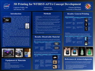
The telescope model, with the upper and lower
bipods printed separately and glued on.
The telescope model after the HIPS has been
dissolved, with increased upper struts, but lower
bipods that were printed separately.
The telescope model, printed in multiple colors
and some parts glued together.
The telescope model after being printed, with the
white HIPS material still attached. The lower
bipods broke while the HIPS was dissolving.