1. Water Conditioning & PurificationM A R C H 2 0 0 7
By Chris Gallagher
Fundamentals of
Electrodeionization (EDI)
Technology
E
lectrodeionization (EDI) has ma-
tured and grown in popularity
since its first commercial introduc-
tion over 18 years ago. The technology
can replace mixed ion exchange in many
applications using a chemical-free pro-
cess to produce high-quality water; how-
ever, the water quality fed to the EDI
system is generally reverse osmosis (RO)
permeate. Because of the competitive na-
ture of the business, better manufactur-
ing and improved designs, the price of
EDI has dropped over 60 percent in the
years since its inception, making it a com-
petitive option.
Life of a water system
With any purchase of equipment, life
cycle, maintenance and cost are impor-
tant factors in the decision-making pro-
cess. For EDI modules there are no
moving parts. EDI systems require power
supplies, valves and piping. The simplic-
ity of EDI systems has been greatly en-
hanced over the years. By maintaining the
pretreatment of the water generation sys-
tem, EDI can have an expected life cycle
greater than five years. (Check with indi-
vidual manufacturers for warranty terms.)
EDI acts as a very sensitive indica-
tor of changes in feedwater and pretreat-
ment. EDI is usually the last piece of pro-
cess equipment in a water generation
system, so if the temperature, TDS or
flow changes, EDI performance will
change.
Types of units and process
principles
Many new EDI products have en-
tered the market. The first commercial
EDI was a plate and frame device that
had thin purifying spacers of ~0.100
inches; these systems are still offered to-
day. Thick purifying cell EDI entered the
market in the mid ‘90s, offering a thick-
ness of > 0.200 inches. Spiral EDI pre-
miered at the same time, offering a
different cell pair configuration outside
of the plate and frame.
Regardless of the manufacturer, the
same fundamental principles are com-
mon among all suppliers. The EDI device
uses cell pairs: one cell (chamber) is for
ion depletion, the purifying cell. Juxta-
posed to the purifying cell is a concen-
trate cell. One purifying cell and one
concentrating cell comprise a cell pair
and there are many cells in a module.
Each cell is separated by alternating an-
ion and cation exchange membranes. The
purifying cell is filled with ion exchange
resin and some designs incorporate con-
ductive material in the concentrate and
electrode chambers. There are two elec-
trodes (where voltage is applied): an an-
ode that attracts anions and a cathode
that attracts cations.
When DC voltage is applied, ions in
the purifying compartment move to their
respective nodes. The ions move out of
the bulk solutions and through the ion
exchange membranes, where they are
captured in the concentrating compart-
ment and leave the EDI module.
One of the unique principles of EDI
is when enough ions are transferred,
water splitting or polarization occurs.
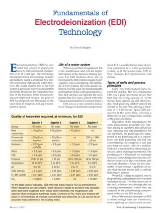
Quality of feedwater required, at minimum, for EDI
Supplier 1 Supplier 2 Supplier 3 Supplier 4
Source RO water RO water RO water RO water
Feed < 40 µS/cm 4-30 µS/cm < 40 µS/cm na
conductivity
Concentrate > 20 µS/cm > 10 µS/cm na 250 to 1,000
conductivity (varies) (varies) µS/cm
Hardness < 0.25 ppm < 1.0 ppm < 1.0 ppm < 2.0 ppm
as CaCO3
Silica < 1.0 ppm < 0.5 ppm < 1.0 ppm < 1.0 ppm
TOC < 0.5 ppm < 0.5 ppm < 0.5 ppm < 0.5 ppm
Pressure 20 to 50 psi < 60 psi 20 to 100 psi 36 to 100 psi
Temperature 10 to 35°C 5 to 35°C 5 to 45°C 5 to 38°C
pH 4 to 10 5 to 9.5 4 to 11 5 to 9
Total chlorine < 0.1 ppm < 0.05 ppm < 0.02 ppm < 0.05 ppm
Fe, Mn, sulfide < 0.01 ppm < 0.01 ppm < 0.01 ppm < 0.01 ppm
CO2
< 10 ppm < 5 ppm na < 10 ppm
As the table above indicates, EDI offerings today require RO as pretreatment.
When designing an EDI system, water recovery needs to be taken into consider-
ation and some suppliers even break down hardness into magnesium and
calcium when evaluating hardness levels. Contrary to RO, there are isolated pH
areas in all chambers of product, concentrate and electrode so LSI cannot be an
accurate measurement for the scaling index.
2. MA R C H 2 0 0 7Water Conditioning & Purification
This is when H2
O breaks down
into H+ (acid component) and
OH-(caustic component). The
presence of H+ and OH- serves to
ionize weakly ionized constitu-
ents such as CO2
, silica and boron;
then allows these weakly ionized
constituents to be transferred from
the bulk solution through their re-
spective membranes and into the
concentrating compartment.
Electrodialysis (ED) has been
commercially available for over 50
years. ED uses the same principles
as EDI; however, to overcome the
concentration polarization effects
that occur in dilute solutions, con-
ductive material (i.e., ion ex-
change resin) was introduced into
the purifying chamber.
In the ‘90s, products were intro-
duced where conductive material was
used in the concentrate cell and elec-
trodes. This was to lower the overall elec-
trical resistance of the EDI module and
to use the current more efficiently.
One spiral EDI device is unique in
that the concentrate flow runs tangen-
tially, or spiral to the product or purify-
ing compartment. The anode is on the
outer layer and the cathode is in the cen-
ter. Concentrate recirculation is recom-
mended for this design. The product
chamber runs parallel to the nodes.
Concentrate recirculation is used in
some designs. The intent is to keep a
good flow distribution in the compart-
ment, support the purifying chamber and
to increase water recovery. Some manu-
facturers have a targeted flow rate
in the concentrate, similar to an
RO reject recycle, hence requiring
the recycle. Again, these are
unique designs created to make
optimal efficiency of the current.
The flow rates of the recycle de-
pend on the manufacturer and
will change with the EDI supplier.
One of the first things suppli-
ers strove for was to create a stan-
dard for EDI design. Today, there
are standards of 50 gpm, 15 gpm,
12.5 gpm, 10 gpm and less, based
on flow per cell pair; more cell
pairs, the higher the flow. Having
multiple modules allows more
flexibility to isolate problems, but
may be more costly for additional
power supplies, piping and instrumen-
tation. Single stack design, or higher ca-
pacity designs with fewer stacks increase
risk and the system may need to be fully
shut down for maintenance.
Many recirculation designs also use
brine injection. The brine injection is in-
tended to lower the overall stack resis-
tance and make better use of the applied
DC voltage.
3. Water Conditioning & PurificationM A R C H 2 0 0 7
Hydraulic/pressure
considerations
When designing an EDI
system, one must look at the
whole water generation sys-
tem. Each EDI module has a
pressure drop across the de-
vice that can range from 15 to
40 psi; each supplier also has
specifications on back pres-
sure, temperature, flow and
TDS. The use of break tanks
may be required when RO
permeate is being used to feed
other processes onsite. If the
RO is feeding directly to the
EDI, one must take the pres-
sure drop across the device
when sizing the high pressure RO pump.
In the System Design (1.) illustration,
we see two different process flows for an
EDI system. The first shows the reject
from both the RO and EDI going to the
drain. In this case, the EDI pressure drop
and piping should be considered when
sizing the high pressure RO pump. In the
second design, an RO storage tank feeds
the EDI. It is recommended that a one µm
filter be used before any EDI that is not
directly fed by the RO. The EDI is not a
filter and cannot take any particulates.
In many cases, the RO storage tank can
inadvertently have particles in it as a re-
sult of normal use.
The System Design (1.) illustration
represents an RO storage tank, but also a
booster pump pre- and post- EDI. If the
EDI storage tank is not local, this may be
necessary.
The System Design (2.) illustration
shows a recycle of the EDI reject. In most
cases, the EDI reject can have a lower TDS
than the RO feed water. However,
special attention needs to be given
to the ions that the RO does not re-
ject and the EDI does. Silica, boron
and CO2
are the three major con-
stituents to look for in the EDI re-
ject. If they are present, there could
be a build up in the system.
Current efficiency
Current efficiency governs all
EDIs. The main factors are flow
rate, total feed water equivalents
and current. Most manufacturers
recommend a nominal flow and
consistency in the feed to produce
consistent EDI water quality. The
current does the work, so changes
in current will directly affect the
water quality. The major factors
that affect all EDIs are: current,
temperature, TDS and fouling. The
higher flow-through lowers the
residence time, thus decreasing the time
the fluid is in the path of the current. The
lower the amperage, the less work the
module is performing.
Variables to be monitored
• Pressure
• Temperature
• Flow rates
— Dilute
— Concentrate
— Electrode
• Voltage
• Amperage
• Conductivity
• Resistivity
Voltage and amperage should be
monitored. This can detect an increase in
overall stack resistance that can be indica-
tive of fouling or of changes in the feed
water. Many thicker cell designs can be
more sensitive to changes in feed water
compared to thinner cell designs. A de-
crease in flow and an increase
in pressure can be indicative
of changes in the feed source
or fouling.
The importance of data
collection is trending. Some
upsets can be seasonal or the
result of events occurring in the
feed source. If the data is
trended, it can predict the per-
formance of the system and
give you the information to
make informed decisions.
Normalization corrects
recorded data and assists with
making educated compari-
sons. For example, tempera-
ture can greatly affect the
performance of certain EDIs. A decrease
of 10°C in temperature could increase
the overall stack resistance by threefold,
hence reducing the amperage and reduc-
ing the water quality; however, it does
not mean the EDI stack may have fouled
or that it needs cleaning. Temperature
effects can be compensated by sizing the
power supply correctly to assure there
is enough voltage or by tempering the
water.
Seasonal effects can include geog-
raphy, naturally occurring events and
feed water source variability (chlorine,
chloramines, hardness, pH and tem-
perature). Seasonal activities can also
affect the water generation system. De-
pending on the geography, feed water
TDS can change throughout the year.
One of the variabilities commonly seen
is the addition of ammonia with chlo-
rine to form chloramines. Total chlorine
(free +chloramines) can irreversibly
damage today’s EDI modules. If a sys-
tem was designed to remove chlo-
rine and not chloramines,
additional processes will be re-
quired. Reduced EDI performance
is due to symptoms in pretreat-
ment processes.
About the author
Chris Gallagher is the Founder and
President of Applied Water Solutions.
He has spent over
18yearsmanaging,
manufacturing
and designing
separation and fil-
tration systems
withinawiderange
of industries. In
addition to his in-
depth experience with conventional
treatment,Gallagherhasspecializedin
troubleshooting, upgrading, testing
and maintaining all types of EDI sys-
zF Qf (Cd
inlet– Cd
outlet ) x 100%
N I
ξ
ξ
=
Where:
= current utilization efficiency, %
= charge of ion
= Faraday's constant, 96,485 amp-s/mol
= diluate flow rate, L/s (= gpm/15.85)
= diluate ED cell inlet ion concentration, mol/L
= diluate ED cell outlet ion concentration, mol/L
= number of cell pairs
= applied current, amps
z
F
Qf
Cd
inlet
Cd
outlet
N
I
Current efficiency: detailed equation
Flow rate (Cd
inlet– Cd
outlet ) 1.31
Current (I)
=
Current efficiency: simplified equation
% Efficiency