
Recommended
More Related Content
What's hot
What's hot (20)
Viewers also liked
Viewers also liked (20)
BORING BARS
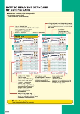
- 1. HOW TO READ THE STANDARD OF BORING BARS a How this section page is organized zOrganized by product series. (Refer to the index on the next page.) FIGURE SHOWING THE TOOLING APPLICATION uses illustrations and arrows to depict available TYPE OF BORING BAR machining applications along with cutting edge indicates the initial letters for the order number, lead angles. as well as applicable insert types. GEOMETRY TITLE OF PRODUCT SERIES CHIP BREAKER BY PRODUCT SECTION PRODUCT FEATURES CUTTING APPLICATION BORING BARS DIMPLE BAR a Excellent vibration resistance due to light dimple head. a Chip disposal is improved by having two channels for chip evacuation. a A laser printed scale on the side for easy installation (Steel shank). a l/d is 3 to 5 times the diameter (Carbide shank is 7 to 8 times the diameter). FSCLC/P CCooinserts, CPooinserts FV Finish SV Light FSTUP TPooinserts FV Finish SV Light Medium MV 95° 93° (06,08,09) (06,08,09) (08,09) (08,09,11,16) (08,09,11,16) Medium CBN PCD CBN 95° 93° F1 F1 MV R/L-F RR° L2 H1 RR° L2 H1 Re Re L1 L1 øD1 5° øD4 øD1 øD4 5° FSCLC1008R/L-06S=1° Right hand tool holder shown. (06,08,09) (06,08,09) Right hand tool holder shown. (08,09,11) (08,09,11,16) Stock Dimensions (mm) Min. Standard Cutting Corner Recom- * Stock Dimensions (mm) Min. Standard Cutting Corner Recom- * Order Number Insert Number Diameter Radius mended Order Number Insert Number Diameter Radius mended D1 Re l/d D1 Re l/d R L D4 L1 L2 F1 H1 RR° (mm) (mm) Ratio Clamp Screw Wrench R L D4 L1 L2 F1 H1 RR° (mm) (mm) Ratio Clamp Screw Wrench CCG/MH BORING BORING FSCLC1008R/L-06S a a NP-CCGT NP-CCGW 0602pp 8 125 18 5 7.2 12 10 0.4 ─3 TS253 TKY08F FSTUP1008R/L-08S a a 0802pp 8 125 18 5 7.2 10 10 0.4 ─3 TS2D TKY06F FSCLP1210R/L-08S a a 0802pp 10 150 22.5 6 9 5 12 0.4 ─3.5 TS3D TKY10F 1210R/L-09S a a 0902pp 10 150 22.5 6 9 8 12 0.4 ─3.5 TS25D TKY08F 1412R/L-08S a a 0802pp 12 150 27 7 11 4 14 0.4 ─4 TS3D TKY10F 1412R/L-09S a a TPGH 0902pp 12 150 27 7 11 7 14 0.4 ─4 TS25D TKY08F CPMH 1612R/L-09S a a 0903pp 12 150 30 8 11 4 16 0.4 ─4 TS4D TKY15F 1210R/L-11S a a TPMH 1103pp 10 150 22.5 6 9 8 12 0.4 ─3.5 TS31D TKY10F NP-CPGB NP-TPGB 1816R/L-09S a a NP-CPMB 0903pp 16 180 36 9 15 3.5 18 0.4 ─5 TS4D TKY15F 1412R/L-11S a a 1103pp 12 150 27 7 11 7 14 0.4 ─4 TS31D TKY10F NP-TPMB NP-CPMH 2220R/L-09S a a 0903pp 20 220 45 11 19 2 22 0.4 ─5 TS4D TKY15F 1816R/L-11S a a NP-TPMH 1103pp 16 180 36 9 15 4 18 0.4 ─5 TS31D TKY10F 3025R/L-09S a a 0903pp 25 250 56.3 15 23.4 0 30 0.4 ─5 TS4D TKY15F 2220R/L-11S a a 1103pp 20 220 45 11 19 0 22 0.4 ─5 TS31D TKY10F * Clamp Torque (N • m) : TS253=1.0, TS3D=2.5, TS4D=3.5 3225R/L-16S a a 1603pp 25 270 56.3 16 23.4 0 32 0.8 ─5 TS4D TKY15F * Clamp Torque (N • m) : TS2D=0.6, TS25D=1.0, TS31D=2.5, TS4D=3.5 FSCLC/P-E Carbide shank with coolant hole CCooinserts, CPooinserts FV Finish SV Light 95° (06,08,09) (06,08,09) FSTUP-E Carbide shank with coolant hole TPooinserts FV Finish SV Light Medium MV Medium CBN 95° F1 MV 93° RR° L2 H1 (08,09) (08,09,11) (08,09,11) Re L1 øD4 øD1 PCD CBN 5° 93° F1 R/L-F FSCLC1008R/L-06E (-2/3, -1/2)=1° Right hand tool holder shown. RR° L2 H1 (06,08,09) (06,08,09) Re L1 øD4 Stock Dimensions (mm) Min. Standard Cutting Corner Recom- * øD1 5° Order Number Insert Number Diameter Radius mended Right hand tool holder shown. (08,09,11) (08,09,11) D1 Re l/d R L D4 L1 L2 F1 H1 RR° (mm) (mm) Ratio Clamp Screw Wrench Stock Dimensions (mm) Min. Cutting Standard Recom- Corner * Order Number Insert Number Diameter Radius mended FSCLC1008R/L-06E a a CCGH 0602pp 8 140 13.8 5 7.2 12 10 0.4 ─7 TS253 TKY08F D1 Re l/d CCMH R L D4 L1 L2 F1 H1 RR° (mm) (mm) Ratio Clamp Wrench 1008R-06E-2/3 a 0602pp 8 90 13.8 5 7.2 12 10 0.4 ─7 TS253 TKY08F Screw NP-CCGT 1008R-06E-1/2 a NP-CCGW 0602pp 8 70 13.8 5 7.2 12 10 0.4 ─7 TS253 TKY08F FSTUP 1008R/L-08E a a 0802pp 8 140 13.8 5 7.2 10 10 0.4 ─7 TS2D TKY06F FSCLP1210R/L-08E a a 0802pp 10 160 16.0 6 9 5 12 0.4 ─7.5 TS3D TKY10F 1008R-08E-2/3 a 0802pp 8 90 13.8 5 7.2 10 10 0.4 ─7 TS2D TKY06F 1210R-08E-2/3 a 0802pp 10 105 16.0 6 9 5 12 0.4 ─7.5 TS3D TKY10F 1008R-08E-1/2 a 0802pp 8 70 13.8 5 7.2 10 10 0.4 ─7 TS2D TKY06F 1210R-08E-1/2 a 0802pp 10 80 16.0 6 9 5 12 0.4 ─7.5 TS3D TKY10F 1210R/L-09E a a 0902pp 10 160 16.0 6 9 8 12 0.4 ─7.5 TS25D TKY08F 1412R/L-08E a a 0802pp 12 180 17.8 7 11 4 14 0.4 ─8 TS3D TKY10F 1210R-09E-2/3 a 0902pp 10 105 16.0 6 9 8 12 0.4 ─7.5 TS25D TKY08F 1412R-08E-2/3 a 0802pp 12 120 17.8 7 11 4 14 0.4 ─8 TS3D TKY10F 1210R-09E-1/2 a 0902pp 10 80 16.0 6 9 8 12 0.4 ─7.5 TS25D TKY08F CPMH TPGH 1412R-08E-1/2 a 0802pp 12 90 17.8 7 11 4 14 0.4 ─8 TS3D TKY10F 1412R/L-09E a a 0902pp 12 180 17.8 7 11 7 14 0.4 ─8 TS25D TKY08F NP-CPGB TPMH 1816R/L-09E a a NP-CPMB 0903pp 16 220 21.8 9 15 3.5 18 0.4 ─8 TS4D TKY15F 1412R-09E-2/3 a NP-TPGB 0902pp 12 120 17.8 7 11 7 14 0.4 ─8 TS25D TKY08F NP-CPMH NP-TPMB 1816R-09E-2/3 a 0903pp 16 145 21.8 9 15 3.5 18 0.4 ─8 TS4D TKY15F 1412R-09E-1/2 a NP-TPMH 0902pp 12 90 17.8 7 11 7 14 0.4 ─8 TS25D TKY08F 1816R-09E-1/2 a 0903pp 16 110 21.8 9 15 3.5 18 0.4 ─8 TS4D TKY15F 1816R/L-11E a a 1103pp 16 220 21.8 9 15 4 18 0.4 ─8 TS31D TKY10F 2220R/L-09E a a 0903pp 20 250 24.0 11 19 2 22 0.4 ─8 TS4D TKY15F 1816R-11E-2/3 a 1103pp 16 145 21.8 9 15 4 18 0.4 ─8 TS31D TKY10F 2220R-09E-2/3 a 0903pp 20 165 24.0 11 19 2 22 0.4 ─8 TS4D TKY15F 1816R-11E-1/2 a 1103pp 16 110 21.8 9 15 4 18 0.4 ─8 TS31D TKY10F 2220R-09E-1/2 a 0903pp 20 125 24.0 11 19 2 22 0.4 ─8 TS4D TKY15F 2220R/L-11E a a 1103pp 20 250 24.0 11 19 0 22 0.4 ─8 TS31D TKY10F Clamp Torque (N • m) : TS253=1.0, TS3D=2.5, TS4D=3.5 2220R-11E-2/3 a 1103pp 20 165 24.0 11 19 0 22 0.4 ─8 TS31D TKY10F * 2220R-11E-1/2 a 1103pp 20 125 24.0 11 19 0 22 0.4 ─8 TS31D TKY10F (Note 1) The insert photos are only examples. The letters refer to the chip breaker and the dimension refers to the inscribed circle. (Note 2) When using insert with right and left hand chip breaker, please use left hand insert for right hand holder and right hand insert for left hand holder. * Clamp Torque (N • m) : TS2D=0.6, TS25D=1.0, TS31D=2.5 CCpp type inserts A088 ─ A091 CUTTING CONDITIONS E012 a : Inventory maintained in Japan. CPpp type inserts A092 TPpp type inserts A105 ─ A107 SPARE PARTS P001 E006 CBN & PCD inserts B036 ─ B039, B056 CBN & PCD inserts B043, B059 TECHNICAL DATA Q001 E007 LEGEND FOR STOCK REFERENCE PAGE PAGE REFERENCE STATUS MARK FOR APPLICABLE INSERTS ·SPARE PARTS is shown on the left hand page indicates reference pages for ·TECHNICAL DATA of each double-page spread. details of inserts that are indicates reference pages, including applicable to the title product. the above, on the right hand page of PRODUCT STANDARDS each double-page spread. indicates order numbers, stock status (per right/left hand), applicable inserts, dimensions, minimum cutting diameters, standard corner radius, recommended l/d ratios, and spare parts. MIN. CUTTING DIAMETER is colour-coded to let you find, at a glance, the maximum / minimum cutting diameters for internal machining. a To Order : Please specify zorder number and hand of tool (right/left). E000
- 2. TURNING TOOLS BORING BARS CLASSIFICATION OF BORING TOOLS .......... E002 IDENTIFICATION .............................................. E004 STANDARD BORING BARS FEATURES OF DIMPLE BAR ...................... E005 DIMPLE BAR................................................. E006 DOUBLE CLAMP DIMPLE BAR................... E013 MICRO-DEX BORING BARS ........................ E016 MICRO-MINI TWIN BORING BARS ............. E019 MICRO-MINI BORING BARS........................ E022 F TYPE BORING BARS ................................ E025 S TYPE BORING BARS................................ E028 P TYPE BORING BARS................................ E035 M TYPE BORING BARS ............................... E039 AL TYPE BORING BARS ............................. E040 D TYPE BORING HEAD ............................... E041 *Arranged by Alphabetical order CpppSTFC E013 Appp-DCLN E028 E012 FSVJB/C E013 Appp-DDUN E017 CpppSTUC E011 FSVPB/C E014 Appp-DSKN E032 CpppSVQC E011 FSVUB/C E014 Appp-DTFN E016 CpppSWUB E027 FSWL1 E015 Appp-DVUN E019 CB E027 FSWL2 E015 Appp-DWLN E020 CR E010 FSWUB/P E039 ApppMWLN E042 DPCL E018 RBH E036 ApppPCLN E042 DPDH E023 RBH E037 ApppPDQN E041 DPDU E030 SpppSCLC E036 ApppPDUN E041 DPTF E034 SpppSCZC E038 ApppPDZN E043 DPVP E031 SpppSDQC E035 ApppPSKN E026 FCTU1 E029 SpppSDUC E035 ApppPTFN E026 FCTU2 E033 SpppSSKC E037 ApppPWLN E006 FSCLC/P E028 SpppSTFC E022 Cpppp-BLS E009 FSDQC E040 SpppSTFE E016 CpppSCLC E008 FSDUC E032 SpppSVQC E030 CpppSCLC E025 FSTU1 E033 SpppSVUC E031 CpppSDQC E025 FSTU2 E024 SBH E029 CpppSDUC E007 FSTUP E001
- 3. BORING BARS CLASSIFICATION '=75° '=91° '=93° ' ' ' Name of Tool Holder Features DIMPLE BAR a The minimum cutting diameter is from &10. a 5°, 7°, 11° positive insert. a Excellent vibration resistance due to a light dimple head. a l/d is 3 to 5 times the diameter (Carbide shank is 7 to 8 times the FSTUP FSDUC FSVUB/C diameter). ^ E007 ^ E008 ^ E011 DOUBLE CLAMP a The minimum cutting diameter is from &32. DIMPLE BAR a a Economical negative insert. Single action type. BORING a Excellent vibration resistance due to a light dimple head. (With coolant hole.) DSKN DTFN DDUN DVUN a l/d is 3 to 4 times the diameter. ^ E014 ^ E014 ^ E013 ^ E015 F Type Boring Bars a The minimum cutting diameter is from & 5.8. a 11°positive insert. a Screw-on type and Clamp-on type. a l/d is 3 to 5 times the diameter. FSTU FCTU a FSWL type is 7°positive insert. ^ E025 ^ E026 S Type Boring Bars a The minimum cutting diameter is from &11. a ISO standard. a 7°positive insert. a Screw-on type. a l/d is 3 to 5 times the diameter SSKC STFC SDUC SVUC (Carbide shank is 7 times the diameter). ^ E033 ^ E028 ^ E029 ^ E033 P Type Boring Bars a The minimum cutting diameter is from & 25. a ISO standard. a Economical negative insert. a Lever lock type, and pin lock type. a l/d is 3 times the diameter. PSKN PTFN PDUN ^ E035 ^ E035 ^ E036 D Type Boring Head a The minimum cutting diameter is from &40. 90° a Economical negative insert. a Lever lock type. a Exchangeable head type. DPTF DPDU ^ E041 ^ E041 M Type Boring Bars a The minimum cutting diameter is from & 32. a Negative trigon shape insert. a Double clamp type. a l/d is 3 times the diameter. AL Type Boring Bars a The minimum cutting diameter is from &20. a Suitable for non-ferrous metal. a 20°positive insert. a Screw-on type. a l/d is 6 times the diameter. STFE a Excellent vibration resistance. ^ E040 MICRO-DEX a The minimum cutting diameter is from &5. a 7°positive insert. Boring Bars a Carbide shank type. (Carbide Shank) a Easy-to-use tool geometries. a Suitable for small workpieces. SWUB STUC a l/d is 5 times the diameter. ^ E016 ^ E017 MICRO-MINI TWIN a The minimum cutting diameter is from &2.2. Boring Bars a Solid carbide type with two cutting edges. a Continuous cutting from boring to facing. a With or without a chip breaker. The minimum cutting diameter is MICRO-MINI a from &3.2. Boring Bars a a Solid carbide type (Single cutting edges). l/d is 5 times the diameter. a Cutting edge can be shaped according to the application. Thus, it covers a wide cutting range CppFR-BLS (threading,grooving,copying, etc.). ^ E022 (Note 1) Holders with blue colour symbol have an anti-vibration carbide shank. (For Micro-dex boring bars, carbide shank only.) E002
- 4. '=93° '=95° '=107°30´ ─117°30´ '=142° '=3°, 5° Selection Standard Low Cutting Resist- Small Diameter Coolant Hole Clamp Rigidity ' Economical Specialized ance (Sharpness) Resistance ' ' ' Operation Efficiency Vibration ' Cutting e * e e e * FSWUB/P FSCLC/P FSDQC FSVPB/C FSVJB/C ^ E010 ^ E006 ^ E009 ^ E011 ^ E012 BORING DCLN DWLN ^ E013 ^ E015 u u * u * FSWL ^ E027 u u * SCLC SDQC SVQC SCZC ^ E030 ^ E031 ^ E032 ^ E034 e u e e PCLN PWLN PDQN PDZN ^ E036 ^ E037 ^ E037 ^ E038 e u e DPCL DPDH DPVP ^ E042 ^ E042 ^ E043 e e u e MWLN ^ E039 e u e e e SCLC ^ E016 e e e CBppRS(-B) CR ^ E019 ^ E020 e e (Note 2) e : 1st recommendation. u : 2nd recommendation. (Note 3) Indicates that the shank material is carbide. * E003
- 5. BORING BARS IDENTIFICATION y DIMPLE BAR nMin.Cutting Diameter mShank Diameter (mm) (mm) 10 10 22 22 08 8 cInsert Shape vCutting Angle 12 12 25 25 10 10 C RHOMBIC 80° U 93° 13 13 30 30 12 12 D RHOMBIC 55° L 95° bInsert Clearance 14 14 32 32 16 16 T TRIANGULAR 60° Q 107°30´ B 5° 16 16 34 34 20 20 zFunction xClamp Structure V RHOMBIC 35° P 117°30´ C 7° 18 18 40 40 25 25 F Fix type S Screw-on W TRIGON J 142° P 11° 20 20 32 32 BORING , . / u 11 F S C L C 10 08 R - 06 E - 2/3 z x c v b n m ,Hand of Tool .Cutting Edge Length (mm) /Shank Material u Tool Length (Carbide shank only) (mm) 11 Inscribed circle 4.76 5.56 6.35 7.94 9.525 E Shank Dia. 8 10 12 16 20 R Right Hand of insert Carbide Shank L Left Hand RHOMBIC 80° – – 06 08 09 S Steel Shank No symbol 140 160 180 220 250 RHOMBIC 55° – – 07 – 11 2/3 90 105 120 145 165 TRIANGULAR 60° 08 09 11 – 16 1/2 70 80 90 110 125 RHOMBIC 35° 08 – 11 – 16 TRIGON L3 – 04 – 06 y ISO TYPE Boring tools [For Aluminium Alloy, M-type, P-type and S-type] S 16 M S C L C R 09 z x c v b n m , . cTool Length zShank Material (mm) vClamp Structure bInsert Shape mInsert Clearance ,Hand of Tool A Steel Shank F 80 M Double Clamp C RHOMBIC 80° C 7°Positive R Right Hand with Coolant Hole H 100 P Lever Lock D RHOMBIC 55° E 20°Positive L Left Hand C Carbide Shank K 125 S Screw-on S SQUARE 90° N 0° E Carbide Shank with Coolant Hole M 150 T TRIANGULAR 60° P 11°Positive S Steel Shank Q 180 V RHOMBIC 35° R 200 W Trigon S 250 T 300 xShank Diameter U 350 (mm) V 400 nCutting Angle .Cutting Edge Length (mm) Inscribed circle 08 8 F 91° of insert 6.35 7.94 9.525 12.70 19.05 10 10 K 75° RHOMBIC 80° 06 08 09 12 19 12 12 L 95° RHOMBIC 55° 07 – 11 15 – 16 16 Q 107°30´ SQUARE 90° – – 09 12 19 20 20 U 93° TRIANGULAR 60° 11 – 16 22 – 25 25 RHOMBIC 35° 11 – 16 – – 32 32 40 40 E004
- 6. FEATURES OF DIMPLE BAR Highly rigid steel shank and a lightweight head configuration Chip disposal is improved by having designed by computer simulation analysis reduces chatter two channels for chip evacuation. and improves the vibration damping properties. The lightweight head with its large dimple reduces chatter. Available in sizes smaller than the ISO standard. Therefore the boring of small diameter holes is possible. The boring bar has a laser printed scale on the shank to facilitate easy BORING installation. "F and FS" breakers improves the quality of the surface finish, "MV" breaker offers excellent chip disposal. High wear resistant CBN inserts are also available for the machining of hardened materials. y DEFLECTION RESISTANCE y VIBRATION RESISTANCE a DIMPLE BAR Weight of the Head Damping Time 49.7g 15.8ms Cutting Force (Principal Force) Cutting Force (Back Force) By reducing the weight of the head, the damping properties are increased. a Conventional Product Weight of the Head Damping Time 70.1g 20ms The unique cross sectional shape engineered into the dimple effectively balances Boring Bar Deflection the cutting forces (principal DIMPLE BAR 28.3!m and back force), and reduces Conventional Bar 34!m deflection by up to 17 %. *The simulation cut=0.5mm,above was conducted with a FSCLP1816R-09S holder, under the following conditions; l/d=5, depth of data stated and feed=0.05mm/rev. y Direction for the use of CCG/MT • CPG/MT • CPMX • TPG/MX type inserts By changing the clamp screw, it is possible to use the inserts listed in the table below. Holder : FSCLC/P • FSCLC/P...E Holder : FSTUP • FSTUP...E Insert Number Clamp Screw Insert Number Clamp Screw CCG/MT0602pp (& 6.35) Can be used as it is. TPG/MX0802pp (& 4.76) Change to CS200T CPG/MT0802pp (& 7.94) Change to TS3 TPG/MX0902pp (& 5.56) Change to CS250T CPG/MT0903pp (& 9.525) Change to TS4 TPG/MX1103pp (& 9.525) Change to CS300890T CPMX0802pp (& 7.94) Can be used as it is. CPMX0903pp (& 9.525) Can be used as it is. * If the screw is too long then please shorten as necessary. (Note) TPMT/W09,W11 types cannot be used due to a different clamp screw size. E005
- 7. BORING BARS DIMPLE BAR a Excellent vibration resistance due to light dimple head. a Chip disposal is improved by having two channels for chip evacuation. a A laser printed scale on the side for easy installation (Steel shank). a l/d is 3 to 5 times the diameter (Carbide shank is 7 to 8 times the diameter). FSCLC/P CCooinserts, CPooinserts FV Finish SV Light 95° (06,08,09) (06,08,09) Medium CBN F1 95° RR° L2 H1 MV Re L1 øD1 5° øD4 FSCLC1008R/L-06S=1° Right hand tool holder shown. (06,08,09) (06,08,09) Stock Dimensions (mm) Min. Cutting Standard Recom- Corner * Order Number Insert Number Diameter Radius mended D1 Re l/d R L D4 L1 L2 F1 H1 RR° (mm) (mm) Ratio Clamp Screw Wrench CCG/MH BORING FSCLC1008R/L-06S a a NP-CCGT NP-CCGW 0602pp 8 125 18 5 7.2 12 10 0.4 ─3 TS253 TKY08F FSCLP1210R/L-08S a a 0802pp 10 150 22.5 6 9 5 12 0.4 ─3.5 TS3D TKY10F 1412R/L-08S a a 0802pp 12 150 27 7 11 4 14 0.4 ─4 TS3D TKY10F CPMH 1612R/L-09S a a NP-CPGB 0903pp 12 150 30 8 11 4 16 0.4 ─4 TS4D TKY15F 1816R/L-09S a a NP-CPMB 0903pp 16 180 36 9 15 3.5 18 0.4 ─5 TS4D TKY15F NP-CPMH 2220R/L-09S a a 0903pp 20 220 45 11 19 2 22 0.4 ─5 TS4D TKY15F 3025R/L-09S a a 0903pp 25 250 56.3 15 23.4 0 30 0.4 ─5 TS4D TKY15F * Clamp Torque (N • m) : TS253=1.0, TS3D=2.5, TS4D=3.5 FSCLC/P-E Carbide shank with coolant hole CCooinserts, CPooinserts FV Finish SV Light 95° (06,08,09) (06,08,09) Medium CBN F1 95° RR° L2 H1 MV Re L1 øD4 øD1 5° FSCLC1008R/L-06E (-2/3, -1/2)=1° Right hand tool holder shown. (06,08,09) (06,08,09) Stock Dimensions (mm) Min. Cutting Standard Recom- Corner * Order Number Insert Number Diameter Radius mended D1 Re l/d R L D4 L1 L2 F1 H1 RR° (mm) (mm) Ratio Clamp Screw Wrench FSCLC1008R/L-06E a a CCGH 0602pp 8 140 13.8 5 7.2 12 10 0.4 ─7 TS253 TKY08F CCMH 1008R-06E-2/3 a 0602pp 8 90 13.8 5 7.2 12 10 0.4 ─7 TS253 TKY08F NP-CCGT 1008R-06E-1/2 a NP-CCGW 0602pp 8 70 13.8 5 7.2 12 10 0.4 ─7 TS253 TKY08F FSCLP1210R/L-08E a a 0802pp 10 160 16.0 6 9 5 12 0.4 ─7.5 TS3D TKY10F 1210R-08E-2/3 a 0802pp 10 105 16.0 6 9 5 12 0.4 ─7.5 TS3D TKY10F 1210R-08E-1/2 a 0802pp 10 80 16.0 6 9 5 12 0.4 ─7.5 TS3D TKY10F 1412R/L-08E a a 0802pp 12 180 17.8 7 11 4 14 0.4 ─8 TS3D TKY10F 1412R-08E-2/3 a 0802pp 12 120 17.8 7 11 4 14 0.4 ─8 TS3D TKY10F CPMH 1412R-08E-1/2 a NP-CPGB 0802pp 12 90 17.8 7 11 4 14 0.4 ─8 TS3D TKY10F 1816R/L-09E a a NP-CPMB 0903pp 16 220 21.8 9 15 3.5 18 0.4 ─8 TS4D TKY15F NP-CPMH 1816R-09E-2/3 a 0903pp 16 145 21.8 9 15 3.5 18 0.4 ─8 TS4D TKY15F 1816R-09E-1/2 a 0903pp 16 110 21.8 9 15 3.5 18 0.4 ─8 TS4D TKY15F 2220R/L-09E a a 0903pp 20 250 24.0 11 19 2 22 0.4 ─8 TS4D TKY15F 2220R-09E-2/3 a 0903pp 20 165 24.0 11 19 2 22 0.4 ─8 TS4D TKY15F 2220R-09E-1/2 a 0903pp 20 125 24.0 11 19 2 22 0.4 ─8 TS4D TKY15F Clamp Torque (N • m) : TS253=1.0, TS3D=2.5, TS4D=3.5 * (Note 1) The insert photos are only examples. The letters refer to the chip breaker and the dimension refers to the inscribed circle. (Note 2) When using insert with right and left hand chip breaker, please use left hand insert for right hand holder and right hand insert for left hand holder. CCpp type inserts A088 ─ A091 a : Inventory maintained in Japan. CPpp type inserts A092 E006 CBN & PCD inserts B036 ─ B039, B056
- 8. FSTUP TPooinserts FV Finish SV Light Medium MV 93° (08,09) (08,09,11,16) (08,09,11,16) PCD CBN 93° F1 R/L-F RR° L2 H1 Re L1 øD1 5° øD4 Right hand tool holder shown. (08,09,11) (08,09,11,16) Stock Dimensions (mm) Min. Cutting Standard Recom- Corner * Order Number Insert Number Diameter Radius mended D1 Re l/d R L D4 L1 L2 F1 H1 RR° (mm) (mm) Ratio Clamp Screw Wrench BORING FSTUP1008R/L-08S a a 0802pp 8 125 18 5 7.2 10 10 0.4 ─3 TS2D TKY06F 1210R/L-09S a a 0902pp 10 150 22.5 6 9 8 12 0.4 ─3.5 TS25D TKY08F 1412R/L-09S a a TPGH 0902pp 12 150 27 7 11 7 14 0.4 ─4 TS25D TKY08F 1210R/L-11S a a TPMH 1103pp 10 150 22.5 6 9 8 12 0.4 ─3.5 TS31D TKY10F NP-TPGB 1412R/L-11S a a NP-TPMB 1103pp 12 150 27 7 11 7 14 0.4 ─4 TS31D TKY10F 1816R/L-11S a a NP-TPMH 1103pp 16 180 36 9 15 4 18 0.4 ─5 TS31D TKY10F 2220R/L-11S a a 1103pp 20 220 45 11 19 0 22 0.4 ─5 TS31D TKY10F 3225R/L-16S a a 1603pp 25 270 56.3 16 23.4 0 32 0.8 ─5 TS4D TKY15F Clamp Torque (N • m) : TS2D=0.6, TS25D=1.0, TS31D=2.5, TS4D=3.5 * FSTUP-E Carbide shank with coolant hole TPooinserts FV Finish SV Light Medium MV 93° (08,09) (08,09,11) (08,09,11) PCD CBN 93° F1 R/L-F RR° L2 H1 Re L1 øD1 øD4 5° Right hand tool holder shown. (08,09,11) (08,09,11) Stock Dimensions (mm) Min. Cutting Standard Recom- Corner * Order Number Insert Number Diameter Radius mended D1 Re l/d R L D4 L1 L2 F1 H1 RR° (mm) (mm) Ratio Clamp Screw Wrench FSTUP 1008R/L-08E a a 0802pp 8 140 13.8 5 7.2 10 10 0.4 ─7 TS2D TKY06F 1008R-08E-2/3 a 0802pp 8 90 13.8 5 7.2 10 10 0.4 ─7 TS2D TKY06F 1008R-08E-1/2 a 0802pp 8 70 13.8 5 7.2 10 10 0.4 ─7 TS2D TKY06F 1210R/L-09E a a 0902pp 10 160 16.0 6 9 8 12 0.4 ─7.5 TS25D TKY08F 1210R-09E-2/3 a 0902pp 10 105 16.0 6 9 8 12 0.4 ─7.5 TS25D TKY08F 1210R-09E-1/2 a 0902pp 10 80 16.0 6 9 8 12 0.4 ─7.5 TS25D TKY08F TPGH 1412R/L-09E a a 0902pp 12 180 17.8 7 11 7 14 0.4 ─8 TS25D TKY08F TPMH 1412R-09E-2/3 a NP-TPGB 0902pp 12 120 17.8 7 11 7 14 0.4 ─8 TS25D TKY08F NP-TPMB 1412R-09E-1/2 a NP-TPMH 0902pp 12 90 17.8 7 11 7 14 0.4 ─8 TS25D TKY08F 1816R/L-11E a a 1103pp 16 220 21.8 9 15 4 18 0.4 ─8 TS31D TKY10F 1816R-11E-2/3 a 1103pp 16 145 21.8 9 15 4 18 0.4 ─8 TS31D TKY10F 1816R-11E-1/2 a 1103pp 16 110 21.8 9 15 4 18 0.4 ─8 TS31D TKY10F 2220R/L-11E a a 1103pp 20 250 24.0 11 19 0 22 0.4 ─8 TS31D TKY10F 2220R-11E-2/3 a 1103pp 20 165 24.0 11 19 0 22 0.4 ─8 TS31D TKY10F 2220R-11E-1/2 a 1103pp 20 125 24.0 11 19 0 22 0.4 ─8 TS31D TKY10F Clamp Torque (N • m) : TS2D=0.6, TS25D=1.0, TS31D=2.5 * CUTTING CONDITIONS E012 TPpp type inserts A105 ─ A107 SPARE PARTS P001 CBN & PCD inserts B043, B059 TECHNICAL DATA Q001 E007
- 9. BORING BARS DIMPLE BAR a Excellent vibration resistance due to light dimple head. a Chip disposal is improved by having two channels for chip evacuation. a A laser printed scale on the side for easy installation (Steel shank). a l/d is 3 to 5 times the diameter (Carbide shank is 7 to 8 times the diameter). FSDUC DCooinserts FV Finish SV Light Medium MV 93° (07,11) (07,11) (07,11) Medium PCD CBN 93° F1 Standard R/L-F RR° H1 F2 Re L2 øD1 L1 øD4 0° Right hand tool holder shown. (07,11) (07,11) (07,11) Stock Dimensions (mm) Min. Cutting Standard Recom- Corner * Order Number Insert Number Diameter Radius mended D1 Re l/d R L D4 L1 L2 F1 F2 H1 RR° (mm) (mm) Ratio Clamp Screw Wrench BORING FSDUC1410R/L-07S a a DCMT 0702pp 10 150 18 8.3 3.3 9 7.5 14 0.4 ─3.5 TS25 TKY08F 1612R/L-07S a a DCET 0702pp 12 150 20 9.3 3.3 11 6 16 0.4 ─4 TS25 TKY08F DCGT 2016R/L-07S a a NP-DCMT 0702pp 16 180 20 11.3 3.3 15 5 20 0.4 ─5 TS25 TKY08F 3220R/L-11S a a NP-DCMW 11T3pp 20 180 22.5 16.1 6.1 19 5 32 0.8 ─5 TS43 TKY15F * Clamp Torque (N • m) : TS25=1.0, TS43=3.5 FSDUC-E Carbide shank with coolant hole DCooinserts FV Finish SV Light Medium MV 93° (07,11) (07,11) (07,11) Medium PCD CBN 93° F1 Standard R/L-F RR° H1 F2 Re L2 øD1 L1 øD4 0° Right hand tool holder shown. (07,11) (07,11) (07,11) Stock Dimensions (mm) Min. Cutting Standard Recom- Corner * Order Number Insert Number Diameter Radius mended D1 Re l/d R L D4 L1 L2 F1 F2 H1 RR° (mm) (mm) Ratio Clamp Screw Wrench FSDUC1410R/L-07E a a DCMT 0702pp 10 160 16.0 8.3 3.3 9 7.5 14 0.4 ─7.5 TS25 TKY08F 1612R/L-07E a a DCET 0702pp 12 180 17.8 9.3 3.3 11 6.0 16 0.4 ─8 TS25 TKY08F DCGT 2016R/L-07E a a NP-DCMT 0702pp 16 220 21.8 11.3 3.3 15 5.0 20 0.4 ─8 TS25 TKY08F 3220R/L-11E a a NP-DCMW 11T3pp 20 250 24.0 16.1 6.1 19 5.0 32 0.8 ─8 TS43 TKY15F Clamp Torque (N • m) : TS25=1.0, TS43=3.5 * (Note 1) The insert photos are only examples. The letters refer to the chip breaker and the dimension refers to the inscribed circle. (Note 2) When using insert with right and left hand chip breaker, please use left hand insert for right hand holder and right hand insert for left hand holder. a : Inventory maintained in Japan. DCpp type inserts A093 ─ A096 E008 CBN & PCD inserts B040, B041, B057