1. CHAPTER 1
1. INTRODUCTION
Nowadays, car is one the most important transportation for each individual
compare to public transport .The high demand of the private transportation
has caused so many problems. For instance, the needs of parking space are
getting critical especially at the shopping area. Therefore, alternative choice
for those who are unable to get indoor parking or even prefer low fee parking
will looking for open parking space. It creates another problem to the car
where the temperature inside the cabin will tremendously increased
approaching 60°C.This will make the driver and passenger become
uncomfortable while entering the car. Moreover, the car can also having car
aging problem and bring damage to the goods found in the car.
.
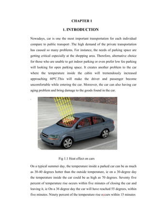
Fig 1.1 Heat effect on cars
On a typical summer day, the temperature inside a parked car can be as much
as 30-40 degrees hotter than the outside temperature, ie on a 30-degree day
the temperature inside the car could be as high as 70 degrees. Seventy five
percent of temperature rise occurs within five minutes of closing the car and
leaving it, ie On a 36 degree day the car will have reached 55 degrees, within
five minutes. Ninety percent of the temperature rise occurs within 15 minutes
2. CHAPTER 2
2. LITERATURE REVIEW
Much work has been conducted in the area of reducing car cabin temperature.
The following is a brief summary of this work.
The literature review reveals that many researchers carried out CFD work
(Mezrhab and Bouzidi, 2006; Kaynakli et al., 2002). Intelligent solar-powered
automobile-ventilation system was studied by David etal ., (2005). Mezrhab
and Bouzidi (2006) developed a numerical model to study the behaviour of
thermal comfort inside the passenger car compartment according to climatic
conditions and materials that compose the vehicle. Available thin films on the
glass window cannot maintain comfortable temperature inside the. This
investigation also found that the existing ventilation is not enough to meet the
. The main objectives of these work is to identify the key point of the vehicle
compartment and placed the ventilator system for optimum performance. In
addition,this work also attempts to improve the existing ventilator system and
use the solar energy to run the ventilator. The ventilator was refurbished by
using the solar controller,additional battery, and solar panel for uninterrupted
running of the ventilator. A bigger motor was used to increase the air flow
rate. The position of the existing ventilator’s solar panel was not suitable
because it was at the side of a car. As a result, the solar panel was not directly
receiving the sunlight. In this experiment the solar panel was placed on the
roof of the car to improve its efficiency to produce electricity.
2
3. CHAPTER 3
3. SOLAR POWERED HEAT CONTROL SYSTEM
A device was fabricated that controls the heat development rate in parked
cars with the help of solar energy powering. The working of this device is
based on Newton’s law of cooling. A study is conducted to measure the
temperature inside of the cars that all directly exposed to the sun, with no
major shadows on any of them and activities to choose the suitable apparatus
that will be used to develop a device for dissipating heat from a car. System
consists of two micro high efficiency fans for circulation of air into and out of
the parked cars. One fan is for inlet and the other for outlet actions
respectively. The inlet air forced in by the micro fan is passed through a
closed chamber containing a coolant. The coolant primarily used is liquid
acetone. The electric power required for the functioning of the two micro fans
are harnessed by solar panels by solar energy harnessing principle
Fig 3.1 Solar powered heat control system
3
4. Table 3.1 components (solar powered heat controlling system)
3.1. METHOD AND DISCUSSION
Our device can control the heat development rate is called a heat control
system .In this paper the device controls the heat development rate in parked
cars with the help of solar energy powering. The working of this device is
based on Newton’s law of cooling by heat removal inside a car which will
help to cooling down the temperature in the car
Fig 3.2Block diagram of solar heat control system
The figure shows the simple block diagram of solar powered heat control
system. The heat control device consists of two micro fans one for inlet and
4
5. the other for outlet and a cooling chamber in the inlet side. the inlet
atmospheric air fed to the device is passed through a cooling chamber
consisting of liquid acetone .the cooled air is circulated in the car cabin due to
inlet fan force andthe warm cabin air is pushed out through the outlet of the
device .the primary source of power for the operation is harnessed from solar
panel
3.2 DESIGN SPECIFICATIONS
The frame being the most important part of the system had to be designed
first. We first made a model of the frame and tested it on a car. Finally, we
had to improve our design. Designing of the frame was mainly done on
AutoCAD. The final frame structure was fabricated with 2mm thick iron
sheet by gas welding operation.
Fig 3.3 Sectional side view
5
6. The frame was designed in such a way that the inlet side can hold a coolant
chamber which has the shape of the English alphabet “U”. The bottom of the
coolant chamber is 2cm thick and the sides being 1cm each.
3.3 SPECIFICATIONSOF FRAME
Frame material thick : iron sheet 2mm
Length : 16.8 cm
Breadth : 13 cm
Inlet area : 6.4 x3.5 cm2
Outlet area : 8.4 x3.5 cm2
The other components used were 280mm square CPU micro fans for inlet and
outlet. As the coolant Acetone, which has boiling point at 56.2°C was used in
the acetone chamber which was a part of the frame. The power for running
the fans was generated by a 10W solar panel. A flux hose was also used so
that the inlet air would be dispersed as far away from the outlet mouth of the
frame thus avoiding scavenging of the cool inlet air through the outlet port.
The final component used was a digital thermometer that allowed to measure
the slightest variation in temperature accurately.
6
7. Table 3.2 properties of acetone
3.4 TEST AND RESULTS
TEST DETAILS
CAR MODEL : Maruti Swift
START OF TEST : 1:00 PM
Afternoon
END OF TEST : 2:00 PM
Afternoon
AVG.AMBIANT ATMO.TEMP : 36.80
c
THERMOMETER HEAD POSITION : middle of car cabin
7
8. CASE
1
2
3
4
SYSTEM DETAILS
Parked Car without system installed
Parked car with system installed (no coolant).
Parked car with system installed (with acetone
coolant)
Parked car with system installed (with acetone
coolant, no flex hose)
Table 3.3 case study details
TEMPERATURE INSIDE CAR
CABIN
FLUX
CASE
AFTER 1 AFTER 5 AFTER 10 HOSE
MINUTE MINUTE MINUTE
1 54.8 57.7 60.5 -
2 53.3 54.1 55.8 Present
3 50.5 54.8 56.4 Present
4 51 52.3 52.1 Not
present
Table 3.4 case study data
8
9. In case I, when the system was not installed, the temperature inside the car
cabin increased with a steady pace. In case II, when the system was installed
with no coolant in it, the temperature inside the car cabin increased with a low
pace for the first 5 minutes, then increased with much higher pace to the next
10 minutes. In case III, when the system was installed with acetone coolant in
it, the temperature inside the car cabin increased with a high pace for the first
5 minutes, then decreased with much lower pace to the next 10 minutes. In
case IV, when the system was installed with acetone coolant in it and with no
flex hose, the temperature inside the car cabin increased with a very low pace
for the first 5 minutes, then decreased with a constant pace to the next 10
minutes and then remained approximately constant The solar powered heat
control system was tested taking into account different case scenarios. It was
observed that the heat control was much observed in Case IV where the car
cabin was installed with the solar powered heat control system containing
acetone coolant and no flex hose. A graph was plotted with the data obtained
during the case study with Time along the X-Axis and Temperature along the
Y axis
Fig 3.4 graphical analysis
10. CHAPTER 4
4. PORTABLE CAR COOLING SYSTEM
The purpose of the car cooling system is to help cool off the parked car under
those hot sunny days. Thus, the aim of this research is to propose a system
that capable to cool the passenger cabin without operates the car's engine.
Materials used are also low cost and has high durability. This portable car
cooling system is used to control or maintain the temperature inside the car at
room temperature even under a very hot conditions. As a result, once the user
starts the car, the air conditioner doesn’t have to work too hard in order to
bring the temperatures at comfortable level. This process reduces the fuel
consumptions and expenses. Besides that, the product is a green product
because it used the Peltier cell to charge the battery.
Fig.4.1 Mechanism for reducing temperature
The car ventilation fan as shown in Fig. 3.1 is using solar system and it can
easily find in the market. This product was created for the purpose to keep car
cool whenever it is overheat by the sunlight or hot surrounding, but there are
differences between this product and portable car cooling system proposed in
this paper in term of the product functions, structure of the product, system
10
11. used, durability and many more. The car ventilator fan shown in Fig. 3.1 used
a solar panel and battery as a source of energy to run the ventilation fan,
while portable car cooling system as shown in Fig. 3.2, applying Peltier cell
as it source of energy. Besides that, the drawback of the car ventilator is only
can be placed if the window’s glass is slightly opened and this action can
actually cause the things that are not desired to happen such as car theft.
Fig.4.2 Portable,light weight, and easy to carry
In addition, the portable car cooling system also easy for transportation and
has a smart design with medium size so that it can be put anywhere in the car.
These are the features that will make this research product to be the people’s
choice. From reliability point of view, the proposed cooling system is more
durable compared to the solar car ventilation fan, it can be seen from the
appearance of the two product, the portable car cooler looks more solid and
durable as we can seen in Fig. 4. Overall, the total weight of the portable car
cooling system is 2.3 kilograms.
11
12. 4.1 DEVELOPMENT OF PORTABLE CAR COOLING SYSTEM
In order to obtain the optimum performance of the product, the design of the
product is the most important. Due to that, Table II demonstrates the function
of the component in the system and Figure 4 illustrates the proposed cooling
system. The materials used for hardware development is white derlin because
this type of material is cheap, lightweight, easy to handle and it easy for
manufacturing purposes. The primary 12VDC motor is used to drive the fan
blades at the speed of 5 meters per second. Simultaneously, the 6Vdc
secondary motor will drive the rotating cloth which has damp after immersion
in water compartment. Interesting here, this system is able to produce wind
with water vapours that creates coolness in the car. The primary button and
secondary button are used for switch on the primary and secondary motors
respectively
Fig.4.3 Concept drawing of Portable Car Cooling system
No doubt, temperature and global warming is increasing. This happens when
the past, people use a lot of pollutants in their everyday lives, including in
power generation activities. Currently, the awareness to protect the
environment is getting better, ie use of green energy such as solar power,
wind and pico hydro. For this product, it uses a Peltier cell as an alternative
12
13. source of electrical energy. This system operates using 12Vdc battery power
type lithium polymer where it is rechargeable. The battery can be charged
either using a charger or more attractive using the Peltier cell. There are
several Peltier cell placed in the left and right as shown in Figure 5. Peltier
cell will produce electricity when one of the surfaces is imposed with hot air
and other surface with cold air. The greater the temperature difference felt by
the Peltier cell, the more electricity is produced. Arguably, it does not work as
expected because the current produced is as low as miliampere(mA).
However, it is believed that it can be a source of alternative energy that can
be considered.
Table 4.1 Functions of the Components in Portable Car Cooler
For the mechanism of this system, the hot air will be sucked into the portable
cooling system due to low air pressure in the system. This is caused by the
high velocity of the propeller blades’ rotation. Then, the hot air will hit the
Peltier cell before the hot air is absorbed by the rolling cloth that has been wet
13
14. and cold. Thus, the hot air is eliminated and the air with vapours of cold water
is discharged into the car cabin.
Fig 4.4 Mechanism for reducing the car cabin temperature
4.2 FUNCTIONALITY TESTING
The functionality testing activities was conducted at an open place under a
hot and scorching sun condition. Refer to the Fig. 3.5, it illustrates that the
temperature inside the car can reach up to 62 oC approximately at 1 o'clock in
the afternoon.Figure 8 shows the temperature in the car with and without the
proposed system taken from 9 in the morning until 4 in the evening. What can
be observed, the temperature inside the car cabin was at its peak between the
hours of 1 o'clock and 2 o'clock in the afternoon. Furthermore, readings taken
from 9 o'clock in the morning slightly increase until 12 o'clock in the
afternoon. However, an hour later, the temperature readings obtained is
14
15. rapidly increased. Unfortunately, after 2 o'clock until 4 o'clock in the
afternoon, the temperature readings decreased at a slower rate.
Fig 4.5 Temperature is high before using the portable car cooling system
Fig 4.6 Temperature is low after using the portable car cooling system
According to the research experimental works, it is proven that the portable
car cooling system is capable to maintain the temperature inside the car in the
range of 250
C to 30o
C as shown in Fig. 3.6. As a result, this product has
improved the quality of air and moisture inside the car's cabin significantly.
15
17. CHAPTER 5
5. CONCLUSION
In the case of solar powered heat controlling system system was installed
with acetone coolant in it and with no flex hose, the temperature inside the car
cabin increased with a very low pace for the first 5 minutes, then decreased
with a constant pace to the next 10 minutes and then remained approximately
constant. Thus it was clear from the above case that the temperature rise
inside the car cabin was overcome by the cooling rate offered by the system,
the device with this configuration showed very improvement in the heat
control activity. The device works completely on green energy and showed an
average of 8.40
C reduction within a short interval and maintained the
temperature inside the car cabin bearable for human body.
In the case of portable car cooling system that able to control and maintain
temperature inside the car at the range of 25 to 30 when parked under very
hot condition. The results of testing shows that the vehicle's owner whom
using this product capable to maintain the cabin car temperature approaching
room temperature. Besides that, the developed portable car cooling system is
in a medium size and the design is suitable for all type of vehicles in
Malaysia. It was proved that this system has good features, high performance
with simple and effective way in reducing the car's cabin temperature.
18. REFERENCE
1. R. Saidur, H.H. Masjuki, M. Hasanuzzaman. (2009). Performance of
an Improved Solar Car Ventilator. International Journal of
Mechanical and Materials Engineering (IJMME), Vol. 4, No. 1, pp
24-34, 2009
2. Mezrhab, M. Bouzidi (2004). “Computation of Thermal Comfort
Inside a Passenger Car 77Compartment”. Applied Thermal
Engineering, 26 (14-15), 1697-1704.
3. Kaynakli, O., Unver, U., Kilic, M. (2002). “Simulation of thermal
comfort heating and cooling periods in an automobile compartment”.
Proceedings of the Automotive Technologies Congress, pp127-135,
24-26 June, Bursa, Turkey.
4. M.A. Jasni and F.M. Nasir. (2012). “Experimental Comparison Study
of the Passive Methods in Reducing Car Cabin Interior Temperature”.
Proceedings of the International Conference on Mechanical,
Automobile and Robotics Engineering (ICMAR’2012), Dec., Penang,
Malaysia
5. R. Saidur, H.H. Masjuki, M. Hasanuzzaman. (2009). Performance
ofan Improved Solar Car Ventilator. International Journal of
Mechanical and Materials Engineering (IJMME), Vol. 4, No.1, pp
24-34, 2009
6. M.A. Jasni and F.M. Nasir. (2012). Experimental Comparison Study
of the Passive Methods in Reducing Car Cabin Interior Temperature.
Proceedings of the International Conference on Mechanical7,
Automobile and Robotics Engineering (ICMAR’2012), pp. 229-233,
December 14-15, Penang, Malaysia
7. M.H. Salah, T. H. Mitchell, J.R. Wagner and D.M. Dawson. (2009).
A Smart Multiple-Loop Automative Cooling System – Model,
Control and Experimental Study. IEEE/ASME Transactions on
Mechatronics, Vol. 15, Issue 1, pp. 117-124.
18