CCS355 Neural Network & Deep Learning UNIT III notes and Question bank .pdf
Ds pe8114 gb_1395
1. Electronic
Pressure Measurement
Pressure Transmitter
Model ECO-1
Data Sheets for related models:
Pressure transmitter ECO-1 for Shipbuilding and Off-Shore; model ECO-1; see data sheet PE 81.18
Pressure transmitter for mobile hydraulic applications; model MH-2; see data sheet PE 81.37
OEM-Pressure Transmitter with ceramic thick film technology; model OC-1; see data sheet PE 81.41
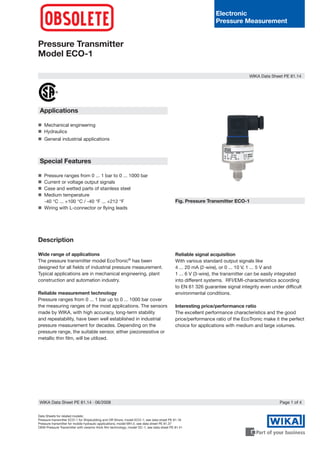
Fig. Pressure Transmitter ECO-1
Applications
Mechanical engineering
Hydraulics
General industrial applications
Special Features
Pressure ranges from 0 ... 1 bar to 0 ... 1000 bar
Current or voltage output signals
Case and wetted parts of stainless steel
Medium temperature
-40 °C ... +100 °C / -40 °F ... +212 °F
Wiring with L-connector or flying leads
Description
Wide range of applications
The pressure transmitter model EcoTronic®
has been
designed for all fields of industrial pressure measurement.
Typical applications are in mechanical engineering, plant
construction and automation industry.
Reliable measurement technology
Pressure ranges from 0 ... 1 bar up to 0 ... 1000 bar cover
the measuring ranges of the most applications. The sensors
made by WIKA, with high accuracy, long-term stability
and repeatability, have been well established in industrial
pressure measurement for decades. Depending on the
pressure range, the suitable sensor, either piezoresistive or
metallic thin film, will be utilized.
Reliable signal acquisition
With various standard output signals like
4 ... 20 mA (2-wire), or 0 ... 10 V, 1 ... 5 V and
1 ... 6 V (3-wire), the transmitter can be easily integrated
into different systems. RFI/EMI-characteristics according
to EN 61 326 guarantee signal integrity even under difficult
environmental conditions.
Interesting price/performance ratio
The excellent performance characteristics and the good
price/performance ratio of the EcoTronic make it the perfect
choice for applications with medium and large volumes.
WIKA Data Sheet PE 81.14
Page 1 of 4WIKA Data Sheet PE 81.14 ∙ 06/2008
2. Specifications Model ECO-1
Pressure ranges bar 1 1.6 2.5 4 6 10 16 25
Over pressure safety bar 5 10 10 17 35 35 50 50
Burst pressure bar 6 12 12 20.5 42 42 80 80
Pressure ranges bar 40 60 100 160 250 400 600 1000
Over pressure safety bar 80 120 200 320 500 800 1200 1500
Burst pressure bar 200 300 500 800 1250 1300 1800 3000
{Absolute pressure: 0 ... 1 bar abs up to 0 ... 16 bar abs}
Materials
■ Wetted parts Stainless steel
■ Case Stainless steel
■ Internal transmission fluid 1)
Synthetic oil
1)
Not with pressure ranges 16 bar.
Power supply UB UB in VDC 10 UB ≤ 30 (14 ... 30 with signal output 0 ... 10 V, 1 ... 6 V)
Signal output and RA in Ohm 4 ... 20 mA, 2-wire RA ≤ (UB – 10 V) / 0.02 A
maximum ohmic load RA 0 ... 10 V, 3-wire RA 10 k
1 ... 5 V, 3-wire RA 5 k
1 ... 6 V, 3-wire RA 6 k
Response time (10 ... 90 %) ms ≤ 5 (≤ 10 ms at medium temperatures below -30°C for pressure ranges up to 16bar
Dielectric strength VDC 500 2)
2)
NEC Class 02 power supply (low voltage and low current max. 100 VA even under fault
conditions)
Accuracy % of span ≤ 0.5 (BFSL)
% of span ≤ 1.0 3)
3)
Including non-linearity, hysteresis, zero point and full scale error (corresponds to error of
measurement per IEC 61298-2).
Adjusted in vertical mounting position with lower pressure connection
Non-linearity % of span ≤ 0.4 (BFSL) according to IEC 61298-2
1-year stability % of span ≤ 0.3 (at reference conditions)
Permissible temperature of
■ Medium 4)
-40 ... +100 °C -40 ... +212 °F
■ Ambience 4)
-30 ... +80 °C -22 ... +176 °F
■ Storage 4)
-30 ... +100 °C -22 ... +212 °F
4)
Also complies with EN 50178, Tab. 7, Operation (C) 4K4H, Storage (D) 1K4, Transport (E) 2K3
Compensated temp. range 0 ... +80 °C 32 ... +176 °F
Temperature coefficients within
compensated temp range
■ Mean TC of zero % of span ≤ 0.4 / 10 K
■ Mean TC of range % of span ≤ 0.3 / 10 K
CE-conformitiy
■ Pressure equipment directive 97/23/EC
■ EMC directive 89/336/EEC emission (class B) and immunity according to EN 61 326
Wiring protection VDC
■ Overvoltage protection 36
■ Short-circuit proofness Sig+ towards UB-
■ Reverse polarity protection UB+ towards UB-
Weight kg Approx. 0.15
Page of 4 WIKA Data Sheet PE 81.14 ∙ 06/2008
{ } Items in curved brackets are optional extras for additional price.
3. Dimensions in mm
Wiring details
Page 3 of 4WIKA Data Sheet PE 81.14 ∙ 06/2008
L-connector
for conductor cross section
up to max. 1.5 mm 2
,
conductor outer diameter 6-8 mm
IP 65
Order code: A4
M 12x1
Circular connector
4-pin
IP 67
Order code: M4
Ingress Protection IP per IEC 60529. The ingress protection classes specified only apply while the pressure transmitter is connected with
female connectors that provide the corresponding ingress protection.
Pressure connections
For installation and safety instructions see the operating instructions for this product.
For tapped holes and welding sockets please see Technical Information IN 00.14 for download at www.wika.de
Flying leads with 1.5m of cable,
for conductor cross section 0.5 mm 2
,
AWG 20 with end splices,
conductor outer diameter 6.8 mm,
IP 67
Order code: DL
Electrical connections
G 1/4
EN 837
Order code: GB
1/4 NPT
per „Nominal size for US
standard tapered pipe
thread NPT“
Order code: NB
DIN 175301-803 A
L-Connector
brown
green
brown
green
white
3-wire2-wire
M 12x1, 4-pin
Circular connector
Flying leads
Legend:
Others on request
4. WIKA Alexander Wiegand GmbH Co. KG
Alexander-Wiegand-Straße 30
63911 Klingenberg/Germany
Tel. +49 / (0) 9372/132-0
Fax +49 / (0) 9372/132-406
E-mail info@wika.de
www.wika.de
Specifications and dimensions given in this leaflet represent the state of engineering at the time of printing.
Modifications may take place and materials specified may be replaced by others without prior notice.
907821506/2008GB
Page 4 of 4 WIKA Data Sheet PE 81.14 ∙ 06/2008
Further pressure transmitter from our OEM production
Fig. Pressure transmitter ECO-1 for Shipbuilding
and Off-Shore with German Lloyd approval
see data sheet PE 81.18
Fig. Pressure transmitter MH-2 with thinfilm technology
for mobile hydraulic applications
see data sheet PE 81.37
Further information
You can obtain further information (data sheets, instructions, etc.) via our internet address
www.wika.de