1. Radio Communication(Module 6)
(Consider a radio transmitter and receiver unit and want to transmit an audio signal
from one place to another. So input to the transmitter is the audio signal(message
signal) which is a low frequency signal. To transmit the audio signal,
modulation(AM/FM) is performed at the transmitter. Modulation will convert the
low frequency audio signal to high frequency signal which is called the modulated
signal. So the output of the transmitter is the Modulated signal which is going to
transmit. Transmitted signal(Modulated signal ) reaches the receiver, where the
receiver will convert modulated signal (high frequency signal) back to the orginal
audio signal(low frequency signal), this process is called Demodulation and which
is performed at the receiver side.) (Above paragraph is given just for
understanding)
Here we are studying about the receiver only.
Input to radio receiver is Modulated signal
Output is Orginal audio signal
Radio Receiver
It is used to extract original audio signal from modulated signal. Widely used radio
receivers are superheterodyne receiver.
Two types
1. AM superheterodyne receiver
2. FM superheterodyne receiver
1. AM superheterodyne receiver
Heterodyne means mixing of two different frequencies
It is used to extract original audio signal from AM modulated signal.
Broadcast frequency range of AM modulated signal - 535KHz to 1605kHZ
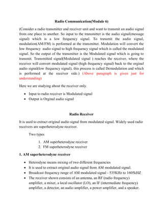
The receiver shown consists of an antenna, an RF (radio frequency)
amplifier, a mixer, a local oscillator (LO), an IF (intermediate frequency)
amplifier, a detector, an audio amplifier, a power amplifier, and a speaker.
2. Antenna:
The antenna picks up all radiated signals from nearby broadcasting stations and
feeds them into the RF amplifier.
RF Amplifier:
This circuit selects only the desired frequency and reject all other frequencies
picked by the antenna.
Local Oscillator:
This circuit generates a steady sine wave of frequency fo.
Mixer :
This circuit accepts two inputs, the amplitude modulated signal from the RF
amplifier and the sinusoidal output of the local oscillator (LO). Mixer mixes these
two signal produce fo-fs as output. The difference frequency(fo-fs) is always 455
KHz and it is termed as intermediate frequency (IF) of AM receiver.
Ganged Tuning
The RF amplifier, Mixer and local oscillator stages are interconnected for
simultaneous tuning.
3. IF Amplifier:
The input to the If amplifier is the 455 KHz AM signal, a replica of the original
AM signal except that the frequency has been lowered to 455 KHz, The IF
amplifier significantly increases the level of this signal.
Detector:
This circuit recovers the modulating signal (audio signal) from the 455 KHz IF.
Audio and Power Amplifiers :
This circuit amplifies the detected audio signal and drives the speaker to produce
sound.
2.FM superheterodyne receiver
It is used to extract original audio signal from FM modulated signal.
Broadcast frequency range of FM modulated signal – 88MHz to 108MHZ
The receiver shown consists of an antenna, an RF (radio frequency)
amplifier, a mixer, a local oscillator (LO), an IF (intermediate frequency)
amplifier, Limiter , a detector, an audio amplifier, a power amplifier, and a
speaker.
4. Antenna:
The antenna picks up all radiated signals from nearby broadcasting stations
and feeds them into the RF amplifier.
RF Amplifier:
This circuit selects only the desired frequency and reject all other
frequencies picked by the antenna.
Local Oscillator:
This circuit generates a steady sine wave of frequency fo.
Mixer :
This circuit accepts two inputs, the Frequency modulated signal from the RF
amplifier and the sinusoidal output of the local oscillator (LO). Mixer mixes
these two signal produce fo-fs as output. The difference frequency(fo-fs) is
always 10.7 MHz and it is termed as intermediate frequency (IF) of FM
receiver.
IF Amplifier:
The input to the If amplifier is the 10.7 MHz FM signal, a replica of the
original FM modulated signal except that the frequency has been lowered to
10.7MHz, The IF amplifier significantly increases the level of this signal.
Limiter
It helps in removing any amplitude variations due to noise pickup during
transmission and improves signal to noise ratio of the system
Detector:
This circuit recovers the modulating signal (audio signal) from the 10.7
MHz IF signal .
Audio and Power Amplifiers :
This circuit amplifies the detected audio signal and drives the speaker to
produce sound.