SlideShare a Scribd company logo
1 of 7
Download to read offline
INGOLD	
Leading Process Analytics
WhitePaper
In chemical plants, petrochemical plants, and refiner-
ies tunable diode lasers (TDLs) are becoming an in-
creasingly common sight. Their high reliability and
low maintenance has made them the gas analyzer
technology of choice for many companies. However,
installation locations and conditions encountered in
some processes have limited their application range.
A portfolio of folded-path TDLs with a unique range of
adaptions has opened the door to measurement op-
portunities previously considered impossible.
TDLs for All Your Processes
Folded-Path Gas Analyzers
Introduction
The rapid rise of TDL analyzers over recent years has led to them
becoming established as a core measurement technology within
the portfolio of gas analysis techniques available today.
The ability of TDLs to interface directly to the process, which
eliminates the need for costly and high-maintenance sample
handling systems, gives them an inherent rapid speed of re-
sponse. This makes them ideal for real-time dynamic measure-
ment of process conditions. Conversely, one aspect of TDLs has
not advanced at the same pace as the measurement technology
itself: the process interface available for cross-stack, in situ
units.
Installing an optical, cross-stack TDL directly in a process pipe
or vessel creates some installation and operational challenges
and limitations which need to be considered carefully before
considering their deployment.
2 METTLER TOLEDO White Paper
and measurement limi-
tations on small pipes
but, due to their large in-
ternal volumes, also ex-
acerbate the stability of
alignment, and provision
and consumption of
purge gas required to
keep the analyzer’s optics
clean.
Optical alignment
Even if space limitations
are not a concern, align-
ment of the transmitter
and receiver units across
the pipe is always a con-
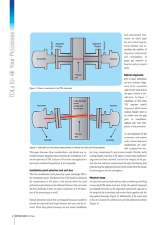
sideration. As Figure 1
illustrates, a cross-stack
TDL requires careful
alignment, which means
mating flanges have to
be welded onto the pipe
prior to installation,
adding cost and com-
plexity to the procedure.
To aid alignment of the
transmitter and receiver
units, various alignment
mechanisms are avail-
able, ranging from sim-
ple, large, compression O-rings to more complex, flexible, metal
sealing designs. Care has to be taken to ensure that satisfactory
alignment has been achieved, and that the integrity of the pro-
cess line has not been compromised through introducing leak
paths during the alignment process which could allow the escape
of process gases into the atmosphere.
Physical mass
An issue that is particularly relevant when considering installing
a cross-stack TDL relates to its size. Firstly, the optical alignment
can degrade over time as the alignment mechanism sags due to
the weight of the transmitter and receiver body together with the
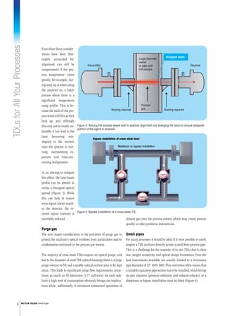
long optical housings (Figure 2). Additionally, if the vessel wall
is thin it is essential to add braces to provide additional stability
(Figure 3).
This paper discusses these considerations, and details new in-
novative process adaptions that overcome the limitations to al-
low the operation of TDL analyzers in locations and applications
previously considered impractical, if not impossible.
Installation point selection and unit size
The first consideration when planning a cross-stack/pipe TDL is
the installation point. The decision has to be based on executing
the measurement at the point in the process where the most
pertinent analysis data can be collected. However, this can create
the first challenge if there are space constraints or if the diam-
eter of the process pipe is small.
Optical restrictions mean that an elongated housing is needed to
provide the required focal length between the laser and the re-
ceiver. These long optical housings not only create installation
Figure 1: Classic cross-stack in situ TDL alignment.
Figure 2: Difficulties of cross-stack measurement on flexible thin walls and hot processes.
TDLsforAllYourProcesses
3 METTLER TOLEDO White Paper
Even when these consider-
ations have been thor-
oughly accounted for,
alignment can still be
compromised if the pro-
cess temperature varies
greatly, for example, dur-
ing start-up or when using
the analyzer on a batch
process where there is a
significant temperature
ramp profile. This is be-
cause the walls of the pro-
cess vessel will flex as they
heat up, and although
this may not be visibly no-
ticeable it can lead to the
laser becoming mis-
aligned to the receiver
once the process is run-
ning, necessitating ex-
pensive and time-con-
suming realignment.
In an attempt to mitigate
this effect, the laser beam
profile can be altered to
create a divergent optical
spread (Figure 3). While
this can help to ensure
some signal always reach-
es the detector, the re-
ceived signal intensity is
inevitably reduced.
Purge gas
The next major consideration is the provision of purge gas to
protect the analyzer’s optical windows from particulates and/or
condensation entrained in the process gas stream.
The majority of cross-stack TDLs require an optical purge, and
due to the diameter of most TDL optical housings there is a large
purge volume to fill and a sizable optical surface area to be kept
clean. This leads to significant purge flow requirements, some-
times as much as 50 liters/min (1.77 cuft/min) for each side.
Such a high level of consumption obviously brings cost implica-
tions while, additionally, it introduces substantial quantities of
diluent gas into the process stream which may create process
quality or other problems downstream.
Small pipes
For many processes it would be ideal if it were possible to easily
employ a TDL analyzer directly across a small bore process pipe.
This is a challenge for the majority of in situ TDLs due to their
size, weight, sensitivity, and optical design limitations. Even the
best instruments available are usually limited to a minimum
pipe diameter of 12” (DIN 300). This restriction often means that
a suitable expansion pipe section has to be installed, which brings
its own concerns (pressure reduction and reduced velocity), or a
slipstream or bypass installation must be fitted (Figure 4).
Figure 3: Bracing the process vessel wall to stabilize alignment and diverging the beam to ensure adequate
portion of the signal is received.
Figure 4: Bypass installation of a cross-stack TDL.
TDLsforAllYourProcesses
4 METTLER TOLEDO White Paper
random fluctuations of the laser beam at the receiver and there-
fore noise on the signal. In addition, the multiple signal paths
further contribute to increased signal noise and measurement
instability. So, in addition to the costs involved in supplying the
purge gas to the measurement location and the high purge con-
sumption, the purge gas can, under some circumstances, cause
degradation of the received signal.
In general, the beam steering effect increases with temperature
and pressure in the process and also with the length of the opti-
cal path through the hot gas. Even if there is no cold purge gas,
beam steering can still cause a significant decrease in measure-
ment quality. In many cases, the benefit of a long optical path
length is mitigated by the signal noise introduced by beam steer-
ing. Therefore, the optical path length should be carefully cho-
sen depending on the process conditions.
As has been outlined above, there exists significant installation
constraints that must be understood when planning to imple-
ment cross-stack TDL analyzers. This raises the question: Can
these constraints be removed so that it is no longer necessary to
adapt the process or plant infrastructure to fit the analyzer, but
instead to make the analyzer fit the plant?
Make the analyzer fit the process
Where can choices be made to overcome the limitations outlined
above? As a general rule a reduction in the weight of the TDL can
go a long way to eliminating concerns regarding alignment
stability and the use of TDLs in tight spaces. Some lighter cross-
stack analyzers are available, but they still require alignment,
which can become more difficult if the optics and beam diameter
Although the bypass ap-
proachcanenableacross-
stack TDL to be installed
on a small pipe, it is not
an ideal solution. Firstly,
in such an arrangement
the optical purge on one
side is working in the di-
rection of process flow,
while the other is working
against the flow. This can
lead to instability of the
optical path length which
in turn will result in mea-
surement error. Secondly,
the purge gas will have
a pronounced dilution effect on the process gas as it passes
through the bypass arm. This inevitably results in a measure-
ment that is not truly representative of the process sample. In
addition, this approach suffers from other drawbacks such as
high optical purge gas consumption and process flow control
considerations, especially as the valves can introduce undesir-
able pressure drops in the line.
Beam steering
The final consideration is more subtle but nonetheless is an
important phenomenon that is relevant to TDL technology. When
a laser beam passes through gases at various temperatures and
therefore different densities and indices of refraction, the beam
will be diffracted at the interface where the density changes.
When using a cross-stack TDL to analyze a hot gas stream this
is exactly what occurs, since typically there will be a non-homo-
geneous temperature distribution and in addition, a high flow
rate of cold purge gas at each end of the optical path. This dif-
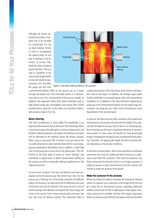
fraction of the laser light is known as “beam steering” and
contributes to signal noise. It affects measurement stability of
the analyzer as well as potentially adding complications to the
alignment process.
As can be seen in Figure 5 the laser and detector have been pre-
aligned across the process pipe (the dotted line). Once the hot
process gas is flowing, due to the fronts created by the different
indices of refraction, the laser beam will be diffracted and some
of the beam may also be reflected. This leads not only to loss of
received energy at the detector, but importantly, laser energy will
arrive at the receiver from various optical paths and some rays
may even miss the detector entirely. The cumulative effect is
Cold purge gas
Transmitter Receiver
Reflection
Diffraction
Steered beam
Beam without
steering
Figure 5: How beam steering affects a TDL analyzer.
TDLsforAllYourProcesses
5 METTLER TOLEDO White Paper
the smaller diameter of the in situ probe and low internal vol-
umes the purge requirement is significantly lower, sometimes as
much as an order of magnitude lower. For gas streams contain-
ing entrained particles or where there is potential for condensa-
tion, purge will remain a necessity, at least for the foreseeable
future, but not all processes fall into this category, as discussed
below.
have also been reduced.
There also still needs to be
opposing flanges fitted
across the pipe and signifi-
cant volumes of purge gas.
When TDLs are being con-
sidered it is often assumed
that they have to be cross-
stack devices. But there is
an alternative. For the ma-
jority of process applica-
tions a folded-path TDL
(where the laser beam
from the sensor head is re-
flected back to a receiver
also in the sensor head) of-
fers a host of advantages:
•	Transmitter and receiv-
er in a single unit and
no need for an expensive
interconnecting cable.
•	Usually single flange
installation
•	No tricky alignment
across the pipe or vessel
•	Order of magnitude re-
duction in purge gas
requirement
•	Small size, so easy to
install in tight spaces
•	Greater accuracy (as
the laser beam passes
through the sample twice)
•	Lightweight design removes stress on flanges and seals.
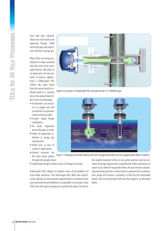
Folded-path TDLs (Figure 6) address many of the problems of
cross-stack analyzers. The advantages they offer have signifi-
cantly opened up measurement opportunities in situations that
have previously proved difficult or impossible to overcome. Such
TDLs may still require purge gas to protect the optics, but due to
Figure 6: Example of a folded-path TDL mounted across a 4 (DN100) pipe.
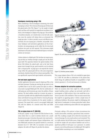
Figure 7: Purge gas dominates optical path with a purge-type probe, but non-purged probe offers a solution.
TDLsforAllYourProcesses
6 METTLER TOLEDO White Paper
Headspace monitoring using a TDL
When considering a TDL for headspace monitoring, the matter
of purging is critical. This is because the purge gas will dominate
the optical path of the TDL (Figure 7) as the sample is largely
static and there will typically be insignificant circulation or ve-
locity in the headspace to displace the purge gas. This would be
a hazardous situation, as it would create a non-fail-safe condi-
tion; since the analyzer will always show an erroneously low
target gas value. In order to provide a secure and effective mea-
surement, the use of purge gas is, therefore, not possible. Since
many headspace and inertization applications are free of par-
ticulates, not using purge gas can be viable. But, for cross-stack
analyzers two ports are still required. This eliminates simple
attachment to the tank and means elaborate bypass or extractive
systems are necessary.
A better solution is a folded-path TDL that does not require purg-
ing and that can interface through a single port into the head-
space itself. The separation between the optical windows of the
device fully defines the optical path, and as the laser beam
passes twice through the gas, good sensitivity can be achieved
with a compact probe. As purge gas is not required the entirety
of gas within the optical path will be at the same temperature
and density, therefore there will be no beam steering effect. This
can significantly improve both signal stability and sensitivity.
Hot and dusty applications
Another application that poses issues for deploying TDLs is hot
and dusty processes. If purge gas entering the gas matrix is not
a problem then it can be used to protect the optics on either a
cross-stack or purged folded-path TDL. But the combination of
cold purge gas and hot process gas raises the problem of beam
steering. The ideal solution would be to remove the purge re-
quirement if possible (with the added benefit of simplified instal-
lation and reduced running costs). However, removing the purge
means another form of protection for the optical windows is
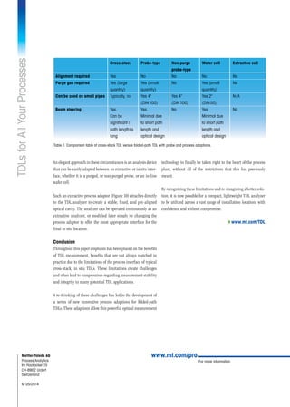
necessary. The answer here is use of a non-purged, folded-path
TDL with the addition of a sintered metal filter and baffle
(Figure 8).
TDL on pipes down to 2 (DIN 50)
In the past, a typical “no-go” location for TDLs has been in situ-
ations where there is a need to interface directly into a small
diameter process pipe. As has been discussed, cross-stack analyz-
ers require complex and expensive bypass configurations, and
even folded-path analyzers are typically limited to a minimum
diameter line of 4” (DIN 100). An innovative in-line process
adaption: the wafer cell (Figure 9), provides the solution.
This unique adaptor allows a TDL to be installed on pipes down
to 2 (DIN 50) and offers no obstruction to the process flow,
which brings the additional benefits of compatibility in high
velocity operation ( 25 m/s) and immunity to vibration.
Process adaption for extractive systems
There are occasions when there might be a fully-serviceable
sample handling system, perhaps one previously used with a
paramagnetic or NDIR analyzer, that a site would like to con-
tinue to use with a TDL installation. There are many reasons that
this might be an appealing option. It allows a simple means of
calibration/validation (the process might be challenging with
high levels of condensates or extreme particulate loads), where
use of a sample conditioning system offers the most appropriate
solution.
Previously, adding a TDL analyzer in these circumstances has
usually meant either; installing a specialized, fixed, extractive-
style TDL; or adding a sample cell to which the transmitter and
receiver housings of a cross-stack analyzer can be attached. This
is a viable solution, but will often mean a large panel is required
to hold the sample cell and analyzer hardware and can be a
significant problem if wall space is at a premium. In another
scenario a test of the performance of a folded-path TDL might be
required before committing to an in situ installation.
Figure 9: TDL with direct process pipe (wafer cell) adaptor.
Figure 10: Extractive process adaptor.
Figure 8: Example of a TDL with a non-purged (NP) process adaptor
and particulate filter.
TDLsforAllYourProcesses
For more information
www.mt.com/proMettler-Toledo AG
Process Analytics
Im Hackacker 15
CH-8902 Urdorf
Switzerland
© 05/2014
An elegant approach in these circumstances is an analysis device
that can be easily adapted between an extractive or in situ inter-
face, whether it is a purged, or non-purged probe, or an in-line
wafer cell.
Such an extractive process adaptor (Figure 10) attaches directly
to the TDL analyzer to create a stable, fixed, and pre-aligned
optical cavity. The analyzer can be operated continuously as an
extractive analyzer, or modified later simply by changing the
process adaptor to offer the most appropriate interface for the
final in situ location.
Conclusion
Throughout this paper emphasis has been placed on the benefits
of TDL measurement, benefits that are not always matched in
practice due to the limitations of the process interface of typical
cross-stack, in situ TDLs. These limitations create challenges
and often lead to compromises regarding measurement stability
and integrity in many potential TDL applications.
A re-thinking of these challenges has led to the development of
a series of new innovative process adaptions for folded-path
TDLs. These adaptions allow this powerful optical measurement
technology to finally be taken right to the heart of the process
plant, without all of the restrictions that this has previously
meant.
By recognizing these limitations and re-imagining a better solu-
tion, it is now possible for a compact, lightweight TDL analyzer
to be utilized across a vast range of installation locations with
confidence and without compromise.
4www.mt.com/TDL
	 Cross-stack	 Probe-type 	 Non-purge	 Wafer cell	 Extractive cell
	 	 	 probe-type
Alignment required	 Yes	 No	 No	 No	 No
Purge gas required	 Yes (large	 Yes (small	 No	 Yes (small	 No
	 quantity)	 quantity)		 quantity)
Can be used on small pipes	 Typically, no	 Yes 4	 Yes 4	 Yes 2	 N / A 			
		 (DIN 100)	 (DIN 100)	 (DIN 50)	
Beam steering	 Yes.	 Yes.	 No	 Yes.	 No
	 Can be	 Minimal due		 Minimal due
	 significant if	 to short path		 to short path
	 path length is	 length and		 length and
	 long	 optical design		 optical design		
Table 1: Comparison table of cross-stack TDL versus folded-path TDL with probe and process adaptions.

More Related Content

Similar to Folded Path Tunable Diode Laser Gas Analyzers

CALIBRATION & VALIDATION PHILOSOPHY AND PROCEDURES FOR TUNEABLE DIODE LASER A...
CALIBRATION & VALIDATION PHILOSOPHY AND PROCEDURES FOR TUNEABLE DIODE LASER A...CALIBRATION & VALIDATION PHILOSOPHY AND PROCEDURES FOR TUNEABLE DIODE LASER A...
CALIBRATION & VALIDATION PHILOSOPHY AND PROCEDURES FOR TUNEABLE DIODE LASER A...ISA Interchange
 
4 biggest mistakes_in_instrumentation_and_how_to_avoid_them
4 biggest mistakes_in_instrumentation_and_how_to_avoid_them4 biggest mistakes_in_instrumentation_and_how_to_avoid_them
4 biggest mistakes_in_instrumentation_and_how_to_avoid_themGanda Siregar
 
An Example for Borehole Seismology in Marmara Sea
An Example for Borehole Seismology in Marmara SeaAn Example for Borehole Seismology in Marmara Sea
An Example for Borehole Seismology in Marmara SeaAli Osman Öncel
 
A life cycle approach to corrosion management and asset integrity
A life cycle approach to corrosion management and asset integrityA life cycle approach to corrosion management and asset integrity
A life cycle approach to corrosion management and asset integrityOkeme Esegine PMP
 
ThomasPorkka_ResearchReport_RETREAT
ThomasPorkka_ResearchReport_RETREATThomasPorkka_ResearchReport_RETREAT
ThomasPorkka_ResearchReport_RETREATThomas Porkka
 
Evaluating Pipeline Operational Integrity - Sand Production
Evaluating Pipeline Operational Integrity - Sand ProductionEvaluating Pipeline Operational Integrity - Sand Production
Evaluating Pipeline Operational Integrity - Sand ProductionVijay Sarathy
 
Manufacturing Optimization IEEE
Manufacturing Optimization IEEEManufacturing Optimization IEEE
Manufacturing Optimization IEEEMichael Logue
 
Selection and Use of Printed Circuit Heat Exchangers
Selection and Use of Printed Circuit Heat ExchangersSelection and Use of Printed Circuit Heat Exchangers
Selection and Use of Printed Circuit Heat ExchangersGerard B. Hawkins
 
EFFECT OF DIMPLES ON FLOW PERFORMANCE OF ENHANCED SURFACE TUBES
EFFECT OF DIMPLES ON FLOW PERFORMANCE OF ENHANCED SURFACE TUBESEFFECT OF DIMPLES ON FLOW PERFORMANCE OF ENHANCED SURFACE TUBES
EFFECT OF DIMPLES ON FLOW PERFORMANCE OF ENHANCED SURFACE TUBESIRJET Journal
 
Innovative Cable Sealing System
Innovative Cable Sealing System Innovative Cable Sealing System
Innovative Cable Sealing System DEEPAK BALONI
 
Rapid Autoclave Blowdown 04.15doc
Rapid Autoclave Blowdown 04.15docRapid Autoclave Blowdown 04.15doc
Rapid Autoclave Blowdown 04.15docKevin Jackson
 
Report cold metal transfer
Report cold metal transferReport cold metal transfer
Report cold metal transferARUNKUMAR648340
 
Heat exchanger series part-1
Heat exchanger series part-1Heat exchanger series part-1
Heat exchanger series part-1pmdeshpande4
 
Heat exchanger series Part-1
Heat exchanger series Part-1Heat exchanger series Part-1
Heat exchanger series Part-1pmdeshpande4
 
Esab world pipelines
Esab world pipelinesEsab world pipelines
Esab world pipelinesJorg Eichhorn
 
Stress Analysis of Buried Pipelines
Stress Analysis of Buried PipelinesStress Analysis of Buried Pipelines
Stress Analysis of Buried PipelinesIRJET Journal
 
Optimizing the Steam Generation Cycle and Condensate Recovery Process
Optimizing the Steam Generation Cycle and Condensate Recovery ProcessOptimizing the Steam Generation Cycle and Condensate Recovery Process
Optimizing the Steam Generation Cycle and Condensate Recovery ProcessM.S. Jacobs & Associates
 

Similar to Folded Path Tunable Diode Laser Gas Analyzers (20)

CALIBRATION & VALIDATION PHILOSOPHY AND PROCEDURES FOR TUNEABLE DIODE LASER A...
CALIBRATION & VALIDATION PHILOSOPHY AND PROCEDURES FOR TUNEABLE DIODE LASER A...CALIBRATION & VALIDATION PHILOSOPHY AND PROCEDURES FOR TUNEABLE DIODE LASER A...
CALIBRATION & VALIDATION PHILOSOPHY AND PROCEDURES FOR TUNEABLE DIODE LASER A...
 
4 biggest mistakes_in_instrumentation_and_how_to_avoid_them
4 biggest mistakes_in_instrumentation_and_how_to_avoid_them4 biggest mistakes_in_instrumentation_and_how_to_avoid_them
4 biggest mistakes_in_instrumentation_and_how_to_avoid_them
 
C021201020023
C021201020023C021201020023
C021201020023
 
An Example for Borehole Seismology in Marmara Sea
An Example for Borehole Seismology in Marmara SeaAn Example for Borehole Seismology in Marmara Sea
An Example for Borehole Seismology in Marmara Sea
 
A life cycle approach to corrosion management and asset integrity
A life cycle approach to corrosion management and asset integrityA life cycle approach to corrosion management and asset integrity
A life cycle approach to corrosion management and asset integrity
 
ThomasPorkka_ResearchReport_RETREAT
ThomasPorkka_ResearchReport_RETREATThomasPorkka_ResearchReport_RETREAT
ThomasPorkka_ResearchReport_RETREAT
 
CGS-LSA IWJT2009 TI UTEK
CGS-LSA IWJT2009 TI UTEKCGS-LSA IWJT2009 TI UTEK
CGS-LSA IWJT2009 TI UTEK
 
Evaluating Pipeline Operational Integrity - Sand Production
Evaluating Pipeline Operational Integrity - Sand ProductionEvaluating Pipeline Operational Integrity - Sand Production
Evaluating Pipeline Operational Integrity - Sand Production
 
Manufacturing Optimization IEEE
Manufacturing Optimization IEEEManufacturing Optimization IEEE
Manufacturing Optimization IEEE
 
Selection and Use of Printed Circuit Heat Exchangers
Selection and Use of Printed Circuit Heat ExchangersSelection and Use of Printed Circuit Heat Exchangers
Selection and Use of Printed Circuit Heat Exchangers
 
EFFECT OF DIMPLES ON FLOW PERFORMANCE OF ENHANCED SURFACE TUBES
EFFECT OF DIMPLES ON FLOW PERFORMANCE OF ENHANCED SURFACE TUBESEFFECT OF DIMPLES ON FLOW PERFORMANCE OF ENHANCED SURFACE TUBES
EFFECT OF DIMPLES ON FLOW PERFORMANCE OF ENHANCED SURFACE TUBES
 
Innovative Cable Sealing System
Innovative Cable Sealing System Innovative Cable Sealing System
Innovative Cable Sealing System
 
Rapid Autoclave Blowdown 04.15doc
Rapid Autoclave Blowdown 04.15docRapid Autoclave Blowdown 04.15doc
Rapid Autoclave Blowdown 04.15doc
 
Report cold metal transfer
Report cold metal transferReport cold metal transfer
Report cold metal transfer
 
Heat exchanger series part-1
Heat exchanger series part-1Heat exchanger series part-1
Heat exchanger series part-1
 
Heat exchanger series Part-1
Heat exchanger series Part-1Heat exchanger series Part-1
Heat exchanger series Part-1
 
Esab world pipelines
Esab world pipelinesEsab world pipelines
Esab world pipelines
 
project
projectproject
project
 
Stress Analysis of Buried Pipelines
Stress Analysis of Buried PipelinesStress Analysis of Buried Pipelines
Stress Analysis of Buried Pipelines
 
Optimizing the Steam Generation Cycle and Condensate Recovery Process
Optimizing the Steam Generation Cycle and Condensate Recovery ProcessOptimizing the Steam Generation Cycle and Condensate Recovery Process
Optimizing the Steam Generation Cycle and Condensate Recovery Process
 

More from Alliance Technical Sales, Inc.

Jogler Magnetic Level Gauge, Magnetostrictive Level Transmitter, and Laser Le...
Jogler Magnetic Level Gauge, Magnetostrictive Level Transmitter, and Laser Le...Jogler Magnetic Level Gauge, Magnetostrictive Level Transmitter, and Laser Le...
Jogler Magnetic Level Gauge, Magnetostrictive Level Transmitter, and Laser Le...Alliance Technical Sales, Inc.
 
Pharmaceutical Waters Guide for Regulatory Compliance, Analysis and Real-Time...
Pharmaceutical Waters Guide for Regulatory Compliance, Analysis and Real-Time...Pharmaceutical Waters Guide for Regulatory Compliance, Analysis and Real-Time...
Pharmaceutical Waters Guide for Regulatory Compliance, Analysis and Real-Time...Alliance Technical Sales, Inc.
 
Analytical Measurement Solutions for Optimization of Your Brewing Process
Analytical Measurement Solutions for Optimization of Your Brewing ProcessAnalytical Measurement Solutions for Optimization of Your Brewing Process
Analytical Measurement Solutions for Optimization of Your Brewing ProcessAlliance Technical Sales, Inc.
 
Jogler Liquid Level Gauges, Indicators and Transmitters
Jogler Liquid Level Gauges, Indicators and TransmittersJogler Liquid Level Gauges, Indicators and Transmitters
Jogler Liquid Level Gauges, Indicators and TransmittersAlliance Technical Sales, Inc.
 
Laser Level Transmitter for Process Measurement and Control
Laser Level Transmitter for Process Measurement and ControlLaser Level Transmitter for Process Measurement and Control
Laser Level Transmitter for Process Measurement and ControlAlliance Technical Sales, Inc.
 
Surface Temperature Sensors and Transmitters for Industrial Applications
Surface Temperature Sensors and Transmitters for Industrial ApplicationsSurface Temperature Sensors and Transmitters for Industrial Applications
Surface Temperature Sensors and Transmitters for Industrial ApplicationsAlliance Technical Sales, Inc.
 
Guide to Oxygen Measurement in Industrial Process Applications
Guide to Oxygen Measurement in Industrial Process ApplicationsGuide to Oxygen Measurement in Industrial Process Applications
Guide to Oxygen Measurement in Industrial Process ApplicationsAlliance Technical Sales, Inc.
 

More from Alliance Technical Sales, Inc. (20)

Jogler Magnetic Level Gauge, Magnetostrictive Level Transmitter, and Laser Le...
Jogler Magnetic Level Gauge, Magnetostrictive Level Transmitter, and Laser Le...Jogler Magnetic Level Gauge, Magnetostrictive Level Transmitter, and Laser Le...
Jogler Magnetic Level Gauge, Magnetostrictive Level Transmitter, and Laser Le...
 
Electric Heating and Freeze Protection Solutions
Electric Heating and Freeze Protection SolutionsElectric Heating and Freeze Protection Solutions
Electric Heating and Freeze Protection Solutions
 
Mettler Toledo Process Analytics Catalog 2018-2019
Mettler Toledo Process Analytics Catalog 2018-2019Mettler Toledo Process Analytics Catalog 2018-2019
Mettler Toledo Process Analytics Catalog 2018-2019
 
Jogler Industrial Level Measurement Products Catalog
Jogler Industrial Level Measurement Products CatalogJogler Industrial Level Measurement Products Catalog
Jogler Industrial Level Measurement Products Catalog
 
Pharmaceutical Waters Guide for Regulatory Compliance, Analysis and Real-Time...
Pharmaceutical Waters Guide for Regulatory Compliance, Analysis and Real-Time...Pharmaceutical Waters Guide for Regulatory Compliance, Analysis and Real-Time...
Pharmaceutical Waters Guide for Regulatory Compliance, Analysis and Real-Time...
 
Analytical Measurement Solutions for Optimization of Your Brewing Process
Analytical Measurement Solutions for Optimization of Your Brewing ProcessAnalytical Measurement Solutions for Optimization of Your Brewing Process
Analytical Measurement Solutions for Optimization of Your Brewing Process
 
Pre-Assembled Self-Regulating Heating Cable
Pre-Assembled Self-Regulating Heating CablePre-Assembled Self-Regulating Heating Cable
Pre-Assembled Self-Regulating Heating Cable
 
Jogler Liquid Level Gauges, Indicators and Transmitters
Jogler Liquid Level Gauges, Indicators and TransmittersJogler Liquid Level Gauges, Indicators and Transmitters
Jogler Liquid Level Gauges, Indicators and Transmitters
 
Pharmaceutical Water Instrumentation Guide
Pharmaceutical Water Instrumentation GuidePharmaceutical Water Instrumentation Guide
Pharmaceutical Water Instrumentation Guide
 
Pharmaceutical Water Guide - Instrumentation
Pharmaceutical Water Guide - InstrumentationPharmaceutical Water Guide - Instrumentation
Pharmaceutical Water Guide - Instrumentation
 
Indigo 200 Series Transmitters
Indigo 200 Series TransmittersIndigo 200 Series Transmitters
Indigo 200 Series Transmitters
 
Laser Level Transmitter for Process Measurement and Control
Laser Level Transmitter for Process Measurement and ControlLaser Level Transmitter for Process Measurement and Control
Laser Level Transmitter for Process Measurement and Control
 
Portable pH Meter for Process Measurement
Portable pH Meter for Process MeasurementPortable pH Meter for Process Measurement
Portable pH Meter for Process Measurement
 
Dissolved Solids Analyzer Refractometer
Dissolved Solids Analyzer RefractometerDissolved Solids Analyzer Refractometer
Dissolved Solids Analyzer Refractometer
 
Temperature and Relative Humidity Data Logger
Temperature and Relative Humidity Data LoggerTemperature and Relative Humidity Data Logger
Temperature and Relative Humidity Data Logger
 
TOC Total Organic Carbon Analyzer
TOC Total Organic Carbon AnalyzerTOC Total Organic Carbon Analyzer
TOC Total Organic Carbon Analyzer
 
Surface Temperature Sensors and Transmitters for Industrial Applications
Surface Temperature Sensors and Transmitters for Industrial ApplicationsSurface Temperature Sensors and Transmitters for Industrial Applications
Surface Temperature Sensors and Transmitters for Industrial Applications
 
Guide to Oxygen Measurement in Industrial Process Applications
Guide to Oxygen Measurement in Industrial Process ApplicationsGuide to Oxygen Measurement in Industrial Process Applications
Guide to Oxygen Measurement in Industrial Process Applications
 
Turbidity Standards for Turbidity Measurement
Turbidity Standards for Turbidity MeasurementTurbidity Standards for Turbidity Measurement
Turbidity Standards for Turbidity Measurement
 
Automated pH Sensor Cleaning and Calibration
Automated pH Sensor Cleaning and CalibrationAutomated pH Sensor Cleaning and Calibration
Automated pH Sensor Cleaning and Calibration
 

Recently uploaded

Top Rated Call Girls In chittoor 📱 {7001035870} VIP Escorts chittoor
Top Rated Call Girls In chittoor 📱 {7001035870} VIP Escorts chittoorTop Rated Call Girls In chittoor 📱 {7001035870} VIP Escorts chittoor
Top Rated Call Girls In chittoor 📱 {7001035870} VIP Escorts chittoordharasingh5698
 
Unit 1 - Soil Classification and Compaction.pdf
Unit 1 - Soil Classification and Compaction.pdfUnit 1 - Soil Classification and Compaction.pdf
Unit 1 - Soil Classification and Compaction.pdfRagavanV2
 
Block diagram reduction techniques in control systems.ppt
Block diagram reduction techniques in control systems.pptBlock diagram reduction techniques in control systems.ppt
Block diagram reduction techniques in control systems.pptNANDHAKUMARA10
 
VIP Call Girls Ankleshwar 7001035870 Whatsapp Number, 24/07 Booking
VIP Call Girls Ankleshwar 7001035870 Whatsapp Number, 24/07 BookingVIP Call Girls Ankleshwar 7001035870 Whatsapp Number, 24/07 Booking
VIP Call Girls Ankleshwar 7001035870 Whatsapp Number, 24/07 Bookingdharasingh5698
 
Unit 2- Effective stress & Permeability.pdf
Unit 2- Effective stress & Permeability.pdfUnit 2- Effective stress & Permeability.pdf
Unit 2- Effective stress & Permeability.pdfRagavanV2
 
UNIT - IV - Air Compressors and its Performance
UNIT - IV - Air Compressors and its PerformanceUNIT - IV - Air Compressors and its Performance
UNIT - IV - Air Compressors and its Performancesivaprakash250
 
Generative AI or GenAI technology based PPT
Generative AI or GenAI technology based PPTGenerative AI or GenAI technology based PPT
Generative AI or GenAI technology based PPTbhaskargani46
 
2016EF22_0 solar project report rooftop projects
2016EF22_0 solar project report rooftop projects2016EF22_0 solar project report rooftop projects
2016EF22_0 solar project report rooftop projectssmsksolar
 
Introduction to Serverless with AWS Lambda
Introduction to Serverless with AWS LambdaIntroduction to Serverless with AWS Lambda
Introduction to Serverless with AWS LambdaOmar Fathy
 
VIP Model Call Girls Kothrud ( Pune ) Call ON 8005736733 Starting From 5K to ...
VIP Model Call Girls Kothrud ( Pune ) Call ON 8005736733 Starting From 5K to ...VIP Model Call Girls Kothrud ( Pune ) Call ON 8005736733 Starting From 5K to ...
VIP Model Call Girls Kothrud ( Pune ) Call ON 8005736733 Starting From 5K to ...SUHANI PANDEY
 
Call Girls Pimpri Chinchwad Call Me 7737669865 Budget Friendly No Advance Boo...
Call Girls Pimpri Chinchwad Call Me 7737669865 Budget Friendly No Advance Boo...Call Girls Pimpri Chinchwad Call Me 7737669865 Budget Friendly No Advance Boo...
Call Girls Pimpri Chinchwad Call Me 7737669865 Budget Friendly No Advance Boo...roncy bisnoi
 
KubeKraft presentation @CloudNativeHooghly
KubeKraft presentation @CloudNativeHooghlyKubeKraft presentation @CloudNativeHooghly
KubeKraft presentation @CloudNativeHooghlysanyuktamishra911
 

Recently uploaded (20)

Top Rated Call Girls In chittoor 📱 {7001035870} VIP Escorts chittoor
Top Rated Call Girls In chittoor 📱 {7001035870} VIP Escorts chittoorTop Rated Call Girls In chittoor 📱 {7001035870} VIP Escorts chittoor
Top Rated Call Girls In chittoor 📱 {7001035870} VIP Escorts chittoor
 
Unit 1 - Soil Classification and Compaction.pdf
Unit 1 - Soil Classification and Compaction.pdfUnit 1 - Soil Classification and Compaction.pdf
Unit 1 - Soil Classification and Compaction.pdf
 
(INDIRA) Call Girl Meerut Call Now 8617697112 Meerut Escorts 24x7
(INDIRA) Call Girl Meerut Call Now 8617697112 Meerut Escorts 24x7(INDIRA) Call Girl Meerut Call Now 8617697112 Meerut Escorts 24x7
(INDIRA) Call Girl Meerut Call Now 8617697112 Meerut Escorts 24x7
 
Block diagram reduction techniques in control systems.ppt
Block diagram reduction techniques in control systems.pptBlock diagram reduction techniques in control systems.ppt
Block diagram reduction techniques in control systems.ppt
 
VIP Call Girls Ankleshwar 7001035870 Whatsapp Number, 24/07 Booking
VIP Call Girls Ankleshwar 7001035870 Whatsapp Number, 24/07 BookingVIP Call Girls Ankleshwar 7001035870 Whatsapp Number, 24/07 Booking
VIP Call Girls Ankleshwar 7001035870 Whatsapp Number, 24/07 Booking
 
Unit 2- Effective stress & Permeability.pdf
Unit 2- Effective stress & Permeability.pdfUnit 2- Effective stress & Permeability.pdf
Unit 2- Effective stress & Permeability.pdf
 
Call Girls in Ramesh Nagar Delhi 💯 Call Us 🔝9953056974 🔝 Escort Service
Call Girls in Ramesh Nagar Delhi 💯 Call Us 🔝9953056974 🔝 Escort ServiceCall Girls in Ramesh Nagar Delhi 💯 Call Us 🔝9953056974 🔝 Escort Service
Call Girls in Ramesh Nagar Delhi 💯 Call Us 🔝9953056974 🔝 Escort Service
 
UNIT - IV - Air Compressors and its Performance
UNIT - IV - Air Compressors and its PerformanceUNIT - IV - Air Compressors and its Performance
UNIT - IV - Air Compressors and its Performance
 
Cara Menggugurkan Sperma Yang Masuk Rahim Biyar Tidak Hamil
Cara Menggugurkan Sperma Yang Masuk Rahim Biyar Tidak HamilCara Menggugurkan Sperma Yang Masuk Rahim Biyar Tidak Hamil
Cara Menggugurkan Sperma Yang Masuk Rahim Biyar Tidak Hamil
 
(INDIRA) Call Girl Aurangabad Call Now 8617697112 Aurangabad Escorts 24x7
(INDIRA) Call Girl Aurangabad Call Now 8617697112 Aurangabad Escorts 24x7(INDIRA) Call Girl Aurangabad Call Now 8617697112 Aurangabad Escorts 24x7
(INDIRA) Call Girl Aurangabad Call Now 8617697112 Aurangabad Escorts 24x7
 
Generative AI or GenAI technology based PPT
Generative AI or GenAI technology based PPTGenerative AI or GenAI technology based PPT
Generative AI or GenAI technology based PPT
 
2016EF22_0 solar project report rooftop projects
2016EF22_0 solar project report rooftop projects2016EF22_0 solar project report rooftop projects
2016EF22_0 solar project report rooftop projects
 
Call Now ≽ 9953056974 ≼🔝 Call Girls In New Ashok Nagar ≼🔝 Delhi door step de...
Call Now ≽ 9953056974 ≼🔝 Call Girls In New Ashok Nagar  ≼🔝 Delhi door step de...Call Now ≽ 9953056974 ≼🔝 Call Girls In New Ashok Nagar  ≼🔝 Delhi door step de...
Call Now ≽ 9953056974 ≼🔝 Call Girls In New Ashok Nagar ≼🔝 Delhi door step de...
 
FEA Based Level 3 Assessment of Deformed Tanks with Fluid Induced Loads
FEA Based Level 3 Assessment of Deformed Tanks with Fluid Induced LoadsFEA Based Level 3 Assessment of Deformed Tanks with Fluid Induced Loads
FEA Based Level 3 Assessment of Deformed Tanks with Fluid Induced Loads
 
Introduction to Serverless with AWS Lambda
Introduction to Serverless with AWS LambdaIntroduction to Serverless with AWS Lambda
Introduction to Serverless with AWS Lambda
 
VIP Model Call Girls Kothrud ( Pune ) Call ON 8005736733 Starting From 5K to ...
VIP Model Call Girls Kothrud ( Pune ) Call ON 8005736733 Starting From 5K to ...VIP Model Call Girls Kothrud ( Pune ) Call ON 8005736733 Starting From 5K to ...
VIP Model Call Girls Kothrud ( Pune ) Call ON 8005736733 Starting From 5K to ...
 
Water Industry Process Automation & Control Monthly - April 2024
Water Industry Process Automation & Control Monthly - April 2024Water Industry Process Automation & Control Monthly - April 2024
Water Industry Process Automation & Control Monthly - April 2024
 
Call Girls Pimpri Chinchwad Call Me 7737669865 Budget Friendly No Advance Boo...
Call Girls Pimpri Chinchwad Call Me 7737669865 Budget Friendly No Advance Boo...Call Girls Pimpri Chinchwad Call Me 7737669865 Budget Friendly No Advance Boo...
Call Girls Pimpri Chinchwad Call Me 7737669865 Budget Friendly No Advance Boo...
 
Integrated Test Rig For HTFE-25 - Neometrix
Integrated Test Rig For HTFE-25 - NeometrixIntegrated Test Rig For HTFE-25 - Neometrix
Integrated Test Rig For HTFE-25 - Neometrix
 
KubeKraft presentation @CloudNativeHooghly
KubeKraft presentation @CloudNativeHooghlyKubeKraft presentation @CloudNativeHooghly
KubeKraft presentation @CloudNativeHooghly
 

Folded Path Tunable Diode Laser Gas Analyzers

  • 1. INGOLD Leading Process Analytics WhitePaper In chemical plants, petrochemical plants, and refiner- ies tunable diode lasers (TDLs) are becoming an in- creasingly common sight. Their high reliability and low maintenance has made them the gas analyzer technology of choice for many companies. However, installation locations and conditions encountered in some processes have limited their application range. A portfolio of folded-path TDLs with a unique range of adaptions has opened the door to measurement op- portunities previously considered impossible. TDLs for All Your Processes Folded-Path Gas Analyzers Introduction The rapid rise of TDL analyzers over recent years has led to them becoming established as a core measurement technology within the portfolio of gas analysis techniques available today. The ability of TDLs to interface directly to the process, which eliminates the need for costly and high-maintenance sample handling systems, gives them an inherent rapid speed of re- sponse. This makes them ideal for real-time dynamic measure- ment of process conditions. Conversely, one aspect of TDLs has not advanced at the same pace as the measurement technology itself: the process interface available for cross-stack, in situ units. Installing an optical, cross-stack TDL directly in a process pipe or vessel creates some installation and operational challenges and limitations which need to be considered carefully before considering their deployment.
  • 2. 2 METTLER TOLEDO White Paper and measurement limi- tations on small pipes but, due to their large in- ternal volumes, also ex- acerbate the stability of alignment, and provision and consumption of purge gas required to keep the analyzer’s optics clean. Optical alignment Even if space limitations are not a concern, align- ment of the transmitter and receiver units across the pipe is always a con- sideration. As Figure 1 illustrates, a cross-stack TDL requires careful alignment, which means mating flanges have to be welded onto the pipe prior to installation, adding cost and com- plexity to the procedure. To aid alignment of the transmitter and receiver units, various alignment mechanisms are avail- able, ranging from sim- ple, large, compression O-rings to more complex, flexible, metal sealing designs. Care has to be taken to ensure that satisfactory alignment has been achieved, and that the integrity of the pro- cess line has not been compromised through introducing leak paths during the alignment process which could allow the escape of process gases into the atmosphere. Physical mass An issue that is particularly relevant when considering installing a cross-stack TDL relates to its size. Firstly, the optical alignment can degrade over time as the alignment mechanism sags due to the weight of the transmitter and receiver body together with the long optical housings (Figure 2). Additionally, if the vessel wall is thin it is essential to add braces to provide additional stability (Figure 3). This paper discusses these considerations, and details new in- novative process adaptions that overcome the limitations to al- low the operation of TDL analyzers in locations and applications previously considered impractical, if not impossible. Installation point selection and unit size The first consideration when planning a cross-stack/pipe TDL is the installation point. The decision has to be based on executing the measurement at the point in the process where the most pertinent analysis data can be collected. However, this can create the first challenge if there are space constraints or if the diam- eter of the process pipe is small. Optical restrictions mean that an elongated housing is needed to provide the required focal length between the laser and the re- ceiver. These long optical housings not only create installation Figure 1: Classic cross-stack in situ TDL alignment. Figure 2: Difficulties of cross-stack measurement on flexible thin walls and hot processes. TDLsforAllYourProcesses
  • 3. TDLsforAllYourProcesses 3 METTLER TOLEDO White Paper Even when these consider- ations have been thor- oughly accounted for, alignment can still be compromised if the pro- cess temperature varies greatly, for example, dur- ing start-up or when using the analyzer on a batch process where there is a significant temperature ramp profile. This is be- cause the walls of the pro- cess vessel will flex as they heat up, and although this may not be visibly no- ticeable it can lead to the laser becoming mis- aligned to the receiver once the process is run- ning, necessitating ex- pensive and time-con- suming realignment. In an attempt to mitigate this effect, the laser beam profile can be altered to create a divergent optical spread (Figure 3). While this can help to ensure some signal always reach- es the detector, the re- ceived signal intensity is inevitably reduced. Purge gas The next major consideration is the provision of purge gas to protect the analyzer’s optical windows from particulates and/or condensation entrained in the process gas stream. The majority of cross-stack TDLs require an optical purge, and due to the diameter of most TDL optical housings there is a large purge volume to fill and a sizable optical surface area to be kept clean. This leads to significant purge flow requirements, some- times as much as 50 liters/min (1.77 cuft/min) for each side. Such a high level of consumption obviously brings cost implica- tions while, additionally, it introduces substantial quantities of diluent gas into the process stream which may create process quality or other problems downstream. Small pipes For many processes it would be ideal if it were possible to easily employ a TDL analyzer directly across a small bore process pipe. This is a challenge for the majority of in situ TDLs due to their size, weight, sensitivity, and optical design limitations. Even the best instruments available are usually limited to a minimum pipe diameter of 12” (DIN 300). This restriction often means that a suitable expansion pipe section has to be installed, which brings its own concerns (pressure reduction and reduced velocity), or a slipstream or bypass installation must be fitted (Figure 4). Figure 3: Bracing the process vessel wall to stabilize alignment and diverging the beam to ensure adequate portion of the signal is received. Figure 4: Bypass installation of a cross-stack TDL.
  • 4. TDLsforAllYourProcesses 4 METTLER TOLEDO White Paper random fluctuations of the laser beam at the receiver and there- fore noise on the signal. In addition, the multiple signal paths further contribute to increased signal noise and measurement instability. So, in addition to the costs involved in supplying the purge gas to the measurement location and the high purge con- sumption, the purge gas can, under some circumstances, cause degradation of the received signal. In general, the beam steering effect increases with temperature and pressure in the process and also with the length of the opti- cal path through the hot gas. Even if there is no cold purge gas, beam steering can still cause a significant decrease in measure- ment quality. In many cases, the benefit of a long optical path length is mitigated by the signal noise introduced by beam steer- ing. Therefore, the optical path length should be carefully cho- sen depending on the process conditions. As has been outlined above, there exists significant installation constraints that must be understood when planning to imple- ment cross-stack TDL analyzers. This raises the question: Can these constraints be removed so that it is no longer necessary to adapt the process or plant infrastructure to fit the analyzer, but instead to make the analyzer fit the plant? Make the analyzer fit the process Where can choices be made to overcome the limitations outlined above? As a general rule a reduction in the weight of the TDL can go a long way to eliminating concerns regarding alignment stability and the use of TDLs in tight spaces. Some lighter cross- stack analyzers are available, but they still require alignment, which can become more difficult if the optics and beam diameter Although the bypass ap- proachcanenableacross- stack TDL to be installed on a small pipe, it is not an ideal solution. Firstly, in such an arrangement the optical purge on one side is working in the di- rection of process flow, while the other is working against the flow. This can lead to instability of the optical path length which in turn will result in mea- surement error. Secondly, the purge gas will have a pronounced dilution effect on the process gas as it passes through the bypass arm. This inevitably results in a measure- ment that is not truly representative of the process sample. In addition, this approach suffers from other drawbacks such as high optical purge gas consumption and process flow control considerations, especially as the valves can introduce undesir- able pressure drops in the line. Beam steering The final consideration is more subtle but nonetheless is an important phenomenon that is relevant to TDL technology. When a laser beam passes through gases at various temperatures and therefore different densities and indices of refraction, the beam will be diffracted at the interface where the density changes. When using a cross-stack TDL to analyze a hot gas stream this is exactly what occurs, since typically there will be a non-homo- geneous temperature distribution and in addition, a high flow rate of cold purge gas at each end of the optical path. This dif- fraction of the laser light is known as “beam steering” and contributes to signal noise. It affects measurement stability of the analyzer as well as potentially adding complications to the alignment process. As can be seen in Figure 5 the laser and detector have been pre- aligned across the process pipe (the dotted line). Once the hot process gas is flowing, due to the fronts created by the different indices of refraction, the laser beam will be diffracted and some of the beam may also be reflected. This leads not only to loss of received energy at the detector, but importantly, laser energy will arrive at the receiver from various optical paths and some rays may even miss the detector entirely. The cumulative effect is Cold purge gas Transmitter Receiver Reflection Diffraction Steered beam Beam without steering Figure 5: How beam steering affects a TDL analyzer.
  • 5. TDLsforAllYourProcesses 5 METTLER TOLEDO White Paper the smaller diameter of the in situ probe and low internal vol- umes the purge requirement is significantly lower, sometimes as much as an order of magnitude lower. For gas streams contain- ing entrained particles or where there is potential for condensa- tion, purge will remain a necessity, at least for the foreseeable future, but not all processes fall into this category, as discussed below. have also been reduced. There also still needs to be opposing flanges fitted across the pipe and signifi- cant volumes of purge gas. When TDLs are being con- sidered it is often assumed that they have to be cross- stack devices. But there is an alternative. For the ma- jority of process applica- tions a folded-path TDL (where the laser beam from the sensor head is re- flected back to a receiver also in the sensor head) of- fers a host of advantages: • Transmitter and receiv- er in a single unit and no need for an expensive interconnecting cable. • Usually single flange installation • No tricky alignment across the pipe or vessel • Order of magnitude re- duction in purge gas requirement • Small size, so easy to install in tight spaces • Greater accuracy (as the laser beam passes through the sample twice) • Lightweight design removes stress on flanges and seals. Folded-path TDLs (Figure 6) address many of the problems of cross-stack analyzers. The advantages they offer have signifi- cantly opened up measurement opportunities in situations that have previously proved difficult or impossible to overcome. Such TDLs may still require purge gas to protect the optics, but due to Figure 6: Example of a folded-path TDL mounted across a 4 (DN100) pipe. Figure 7: Purge gas dominates optical path with a purge-type probe, but non-purged probe offers a solution.
  • 6. TDLsforAllYourProcesses 6 METTLER TOLEDO White Paper Headspace monitoring using a TDL When considering a TDL for headspace monitoring, the matter of purging is critical. This is because the purge gas will dominate the optical path of the TDL (Figure 7) as the sample is largely static and there will typically be insignificant circulation or ve- locity in the headspace to displace the purge gas. This would be a hazardous situation, as it would create a non-fail-safe condi- tion; since the analyzer will always show an erroneously low target gas value. In order to provide a secure and effective mea- surement, the use of purge gas is, therefore, not possible. Since many headspace and inertization applications are free of par- ticulates, not using purge gas can be viable. But, for cross-stack analyzers two ports are still required. This eliminates simple attachment to the tank and means elaborate bypass or extractive systems are necessary. A better solution is a folded-path TDL that does not require purg- ing and that can interface through a single port into the head- space itself. The separation between the optical windows of the device fully defines the optical path, and as the laser beam passes twice through the gas, good sensitivity can be achieved with a compact probe. As purge gas is not required the entirety of gas within the optical path will be at the same temperature and density, therefore there will be no beam steering effect. This can significantly improve both signal stability and sensitivity. Hot and dusty applications Another application that poses issues for deploying TDLs is hot and dusty processes. If purge gas entering the gas matrix is not a problem then it can be used to protect the optics on either a cross-stack or purged folded-path TDL. But the combination of cold purge gas and hot process gas raises the problem of beam steering. The ideal solution would be to remove the purge re- quirement if possible (with the added benefit of simplified instal- lation and reduced running costs). However, removing the purge means another form of protection for the optical windows is necessary. The answer here is use of a non-purged, folded-path TDL with the addition of a sintered metal filter and baffle (Figure 8). TDL on pipes down to 2 (DIN 50) In the past, a typical “no-go” location for TDLs has been in situ- ations where there is a need to interface directly into a small diameter process pipe. As has been discussed, cross-stack analyz- ers require complex and expensive bypass configurations, and even folded-path analyzers are typically limited to a minimum diameter line of 4” (DIN 100). An innovative in-line process adaption: the wafer cell (Figure 9), provides the solution. This unique adaptor allows a TDL to be installed on pipes down to 2 (DIN 50) and offers no obstruction to the process flow, which brings the additional benefits of compatibility in high velocity operation ( 25 m/s) and immunity to vibration. Process adaption for extractive systems There are occasions when there might be a fully-serviceable sample handling system, perhaps one previously used with a paramagnetic or NDIR analyzer, that a site would like to con- tinue to use with a TDL installation. There are many reasons that this might be an appealing option. It allows a simple means of calibration/validation (the process might be challenging with high levels of condensates or extreme particulate loads), where use of a sample conditioning system offers the most appropriate solution. Previously, adding a TDL analyzer in these circumstances has usually meant either; installing a specialized, fixed, extractive- style TDL; or adding a sample cell to which the transmitter and receiver housings of a cross-stack analyzer can be attached. This is a viable solution, but will often mean a large panel is required to hold the sample cell and analyzer hardware and can be a significant problem if wall space is at a premium. In another scenario a test of the performance of a folded-path TDL might be required before committing to an in situ installation. Figure 9: TDL with direct process pipe (wafer cell) adaptor. Figure 10: Extractive process adaptor. Figure 8: Example of a TDL with a non-purged (NP) process adaptor and particulate filter.
  • 7. TDLsforAllYourProcesses For more information www.mt.com/proMettler-Toledo AG Process Analytics Im Hackacker 15 CH-8902 Urdorf Switzerland © 05/2014 An elegant approach in these circumstances is an analysis device that can be easily adapted between an extractive or in situ inter- face, whether it is a purged, or non-purged probe, or an in-line wafer cell. Such an extractive process adaptor (Figure 10) attaches directly to the TDL analyzer to create a stable, fixed, and pre-aligned optical cavity. The analyzer can be operated continuously as an extractive analyzer, or modified later simply by changing the process adaptor to offer the most appropriate interface for the final in situ location. Conclusion Throughout this paper emphasis has been placed on the benefits of TDL measurement, benefits that are not always matched in practice due to the limitations of the process interface of typical cross-stack, in situ TDLs. These limitations create challenges and often lead to compromises regarding measurement stability and integrity in many potential TDL applications. A re-thinking of these challenges has led to the development of a series of new innovative process adaptions for folded-path TDLs. These adaptions allow this powerful optical measurement technology to finally be taken right to the heart of the process plant, without all of the restrictions that this has previously meant. By recognizing these limitations and re-imagining a better solu- tion, it is now possible for a compact, lightweight TDL analyzer to be utilized across a vast range of installation locations with confidence and without compromise. 4www.mt.com/TDL Cross-stack Probe-type Non-purge Wafer cell Extractive cell probe-type Alignment required Yes No No No No Purge gas required Yes (large Yes (small No Yes (small No quantity) quantity) quantity) Can be used on small pipes Typically, no Yes 4 Yes 4 Yes 2 N / A  (DIN 100) (DIN 100) (DIN 50) Beam steering Yes. Yes. No Yes. No Can be Minimal due Minimal due significant if to short path to short path path length is length and length and long optical design optical design Table 1: Comparison table of cross-stack TDL versus folded-path TDL with probe and process adaptions.