SlideShare a Scribd company logo
1 of 14
11.NyquistBit Rate Formula
In signal processing,the Nyquistrate,namedafterHarryNyquist,istwice the bandwidthof a
bandlimitedfunctionora bandlimitedchannel.Thistermmeanstwodifferentthingsundertwo
differentcircumstances:asalowerboundforthe sample rate for alias-freesignal sampling(nottobe
confusedwiththe Nyquistfrequency,whichishalf the samplingrate of a discrete-time system)andas
an upperboundforthe symbol rate across a bandwidth-limitedbasebandchannelsuchasa telegraph
lienorpassbandchannel suchasa limitedradiofrequencybandora frequencydivisionmultiplex
channel
C=12log2(1+PN) C=12log2(1+PN) bits per sample
12.Shannon Capacity
ī‚ˇ The Shannonlimitiswhenall issaidindone exceptionallyhardtoascertain(Primakov etal.
2000). Truth be told,the Shannonlimitof the cycle diagramC_5 was notdecidedasTheta(C_5)
=sqrt (5) until 1979 (LovÃĄsz1979), and the Shannonlimitof C_7 is maybe a standoutamongst
the most infamousopenissuesin
extremal combinatorics(Bohman
2003).
ī‚ˇ LovÃĄsz(1979) demonstratedthatthe
Shannonlimitof the (n,r)- Kinserchart
is(n-1; r-1),that of a vertex-transitive
self-reciprocal diagram(which
incorporatesall Paleycharts) Gis
sqrt(|V(G)|),andthatof the Petersen
chart is 4.
ī‚ˇ All charts whose Shannonlimitisknownaccomplishtheirabilityeitheratk=1 (i.e.,attheir
autonomynumber;e.g.,consummate diagrams),k=2(e.g.,self-correlativevertex-transitive
charts includingthe Paleydiagrams),orelse don'tachieve itatany estimationof k(e.g.,the
diagramunionof the cycle chart C_5 witha singletondiagram) (Alonand Lubezki2006).
13.Impairments of Signal
A transmission impairment is a property of a transmission medium which causes the signal to
be degraded, reduced in amplitude, distorted or contaminated. Impairment can introduce
errors into digital signals. Examples of transmission impairments are attenuation, delay
distortion, and several sources of noise including, interference, thermal noise, impulse noise,
and intermodulation noise.
1. Attenuation
ī‚§ Attenuation is a property of the transmission medium. It measures how much
energy is absorbed and/or radiated from the traveling signal due to its
interaction with the transmission medium. Attenuation is measured as a
function of the distance traveled through the transmission medium. A wire or
cable may radiate energy when a signal travels through it. Energy is radiated at a
constant rate (much smaller rate if the cable is shielded) so the longer the
transmission medium the longer the signal is travelling through it and the more
attenuation occurs. When a signal is transmitted through the air the signal
travels in all directions (or some subset of directions with a well-designed
antenna).
2. Dispersion
ī‚§ Dispersion is also a property of the transmission medium. Signals with different
frequencies will travel through a transmission medium with slightly different
velocities. Therefore, the signal will be smeared or distorted when it reaches the
destination.
3. Noise
ī‚§ Noise of different types will affect a transmitting signal. Thermal noise, low
amplitude random noise at predictable low amplitude (amplitude related to the
temperature of the transmission medium), is caused by the thermal vibration of
the molecules within the transmission medium. The difference between signal
levels in a transmitted signal will generally be much larger than the amplitude of
the thermal noise. Thermal noise sets a limit of how close different signal levels
can be at the receiver (larger than the 2X amplitude of the thermal noise).
Thermal noise will not usually be of high enough amplitude to cause the
introduction of bit errors in an encoded signal (unless attenuation has been
excessive)
14.Wave Forms
A waveform is the shape and form of a signal such as a wave moving in a physical medium or an
abstract representation. In many cases, the medium in which the wave propagates does not
permit a direct observation of the true form.
Examples
ī‚ˇ Most programs show waveforms to give the user a visual aid of what has been recorded.
If the waveform is of low or high height (with respect to the {display style x} x axis), the
recording was most likely conducted under conditions with a low or high input volume,
respectively.
Sine Wave
ī‚ˇ A sine wave or sinusoid is a mathematical curve that describes a smooth repetitive
oscillation. A sine wave is a continuous wave.
Square Wave
ī‚ˇ Square waves are universally encountered in digital switching circuits and are naturally
generated by binary (two-level) logic devices. They are used as timing references or
"clock signals", because their fast transitions are suitable for triggering synchronous
logic circuits at precisely determined intervals.
Triangle Wave
ī‚ˇ A triangle wave is a non-sinusoidal waveform named for its triangular shape. It is a
periodic, piecewise linear, continuous real function. Like a square wave, the triangle
wave contains only odd harmonics. However, the higher harmonics roll off much faster
than in a square wave (proportional to the inverse square of the harmonic number as
opposed to just the inverse).
SawtoothWave
ī‚ˇ The sawtooth wave (or saw wave) is a kind of non-sinusoidal waveform. It is so named
based on its resemblance to the teeth of a plain-toothed saw with a zero rake angle.
15.Encoding Digital Data to Digital Signals
ī‚ˇ NRZ- It refers to a variety of digital information transmission within which the binary low
and high states, painted by numerals zero and one.
ī‚ˇ NRZ-I- it's an information recording and transmission methodology that ensures clock
synchronization.
ī‚ˇ Bipolar- Here, zero is painted by no signal line and one represent positive or negative
pulse.
ī‚ˇ Pseudo ternary- A variation of Bipolar AMI is termed Pseudo ternary, here, one is
painted no line signal and zero is positive and negative.
ī‚ˇ Manchester- it's a way of transmittal bits that permits the receiver to simply
synchronize with the sender. this is often a unique coding methodology from alternative
strategies.
ī‚ˇ Differential Manchester- it's NRZ. It modifications its sign state only if there's a change in
information that differs from the previous bit.
16.Digital to Analog
ī‚ˇ Amplitude shift keying- it's a variety of AM that represents digital knowledge as
variations within the amplitude of a radio radiation. it's linear and sensitive.
ī‚ˇ Frequency shift keying- Here, the modification in frequency outline in several digits.
The carrier is switched between two frequencies, 1 and 0.
ī‚ˇ Phase Shift Keying- it's the digital modulation technique within which the part of the
carrier signal is modified by varied the circular function and cos inputs at a specific
time.
17.Analog to Analog
Analog-to-analog conversion, or analog modulation, is the representation of analog information
by an analog signal. Modulation is needed if the medium is bandpass in nature or if only a
bandpass channel is available to us.
There are three ways of modulation
1. Amplitude Modulation (AM)
2.Frequency Modulation (FM)
3.Phase Modulation (PM)
1. Amplitude Modulation (AM)
ī‚§ In AM transmission, the carrier
signal is modulated so that its
amplitude varies with the changing
amplitudes of the modulating signal.
The frequency and phase of the
carrier remain the same.
ī‚§ The modulation creates a bandwidth
that is twice the bandwidth of the
modulating signal and covers a
range centered on the carrier
frequency.
ī‚§ The bandwidth of an audio signal (speech and music) is usually 5 kHz. Therefore, an AM
radio station needs a bandwidth of 10kHz. In fact, the Federal Communications
Commission (FCC) allows 10 kHz for each AM station.
2. Frequency Modulation (FM)
ī‚§ In FM transmission, the frequency of
the carrier signal is modulated to
follow the changing voltage level
(amplitude) of the modulating signal.
The peak amplitude and phase of the
carrier signal remain constant, but as
the amplitude of the information signal
changes, the frequency of the carrier
changes correspondingly.
ī‚§ he actual bandwidth is difficult to
determine exactly, but it can be shown
empirically that it is several times that
of the analog signal or 2(1 β)B where β
is a factor depends on modulation
technique with a common value of 4.
ī‚§ The bandwidth of an audio signal (speech and music) broadcast in stereo is almost 15
kHz. The FCC allows 200 kHz (0.2 MHz) for each station. This mean β = 4 with some extra
guard band.
3.Phase Modulation (PM)
ī‚§ PM transmission, the phase of the carrier
signal is modulated to follow the changing
voltage level (amplitude) of the
modulating signal. The peak amplitude
and frequency of the carrier signal remain
constant, but as the amplitude of the
information signal changes, the phase of
the carrier changes correspondingly.
ī‚§ The actual bandwidth is difficult to
determine exactly, but it can be shown
empirically that it is several times that of the analog signal.
18.Difference BetweenPAM, PWM & PPM
PAM PWM PPM
Pulse amplitude is
variable
constant constant
Pulse width is
constant
variable constant
Bandwidth is less high high
Power of the
transmitter varies
Varies Remains constant
Noise interface is
high
minimum Minimum
Complex system Simpleto implement Simpleto implement
19.Guided & Unguided Media
Telecommunication links can broadly be classed into two categories, namely, guided media
(wired) and unguided media(wireless).
Guided Media
ī‚§ Electrical/Optical signals are passed
through a solid medium (different types
of cables/wires) As the path traversed
by the signals is guided by the size,
shape and length of the wire, this type
of media is called guided media.
ī‚§ E.g., Copper Unshielded Twisted Pair
(UTP), Copper Shielded Twisted Pair (STP), Copper Co-axial cables, Fiber Optic Cables.
Unguided Media
ī‚§ Here information is transmitted by sending electromagnetic signals through free space
and hence the name unguided
media, as the signals are not
guided in any specific direction
or inside any specific medium.
1.Distance separating the end
stations
2.Frequency spectrum used
by the electromagnetic signals
3.Line Encoding technique
used
ī‚§ Based on these attributes, a
wide variety of wireless PHYs and different types of antennas are used in wireless
communication. The diagram given below illustrates different types of antennas
typically used in wireless communication As illustrated in the diagram, antennas can be
of many sizes and shapes.
ī‚§ Wi-Fi, Wi-Max. 3G are example wireless networks used for internet communication.
20.Difference BetweenUTP and STP
ī‚§ Twisted pair cables are widely used in transmitting information, especially across great
distances. The twist in the wire cancels out any magnetic interference that may develop
in the wiring. There are two common types of twisted pair cabling, STP and UTP. The S
stands for Shielded, the U stands for Unshielded, and the TP stands for twisted pair for
both.
UTP STP
It doesn’t have a metal foil cover It does
Its less expensive thanSTP It is expensive thanUTP
Grounding isnot possible It is possible
Very Easy to install Easy to install
Segment length is 500m 100m
Very Easy Maintenance Easy Maintenance
21.DifferentModes of Fiber
Fiber Optics is sending signals down hair-thin strands of
glass or plastic fiber. The light is "guided" down the
center of the fiber called the "core". The core is
surrounded by a optical material called the "cladding"
that traps the light in the core using an optical
technique called "total internal reflection."
1.Single Mode Cable
ī‚§ Single Mode fiber optic cable has a small diametral core
that allows only one mode of light to propagate. Because of
this, the number of light reflections created as the light
passes through the core decreases, lowering attenuation
and creating the ability for the signal to travel further.
2.Multi Mode Cable
ī‚§ Multimode fiber optic cable has
a large diametral core that
allows multiple modes of light
to propagate. Because of this,
the number of light reflections
created as the light passes
through the core increases,
creating the ability for more
data to pass through at a given
time. Because of the high dispersion and attenuation rate with this type of fiber, the
quality of the signal is reduced over long distances.
22.Time DivisionMultiplexing
Time-division multiplexing (TDM) is a method of transmitting and receiving independent signals
over a common signal path by means of synchronized switches at each end of the transmission
line so that each signal appears on the line only a fraction of time in an alternating pattern.
History
ī‚§ Time-division multiplexing was first developed for applications in telegraphy to
route multiple transmissions simultaneously over a single transmission line. In
the 1870s, Émile Baudot developed a time-multiplexing system of multiple
Hughes telegraph machines. In 1953 a 24-channel TDM was placed in
commercial operation by RCA Communications to send audio information
between RCA's facility on Broad Street, New York, their transmitting station at
Rocky Point and the receiving station at Riverhead, Long Island, New York.
Multiplexed Digital Transmission
ī‚§ In circuit-switched networks, such as the public switched telephone network
(PSTN), it is desirable to transmit multiple subscriber calls over the same
transmission medium to effectively utilize the bandwidth of the medium. TDM
allows transmitting and receiving telephone switches to create channels
(tributaries) within a transmission stream. A standard DS0 voice signal has a data
bit rate of 64 kbit/s. A TDM circuit runs at a much higher signal bandwidth,
permitting the bandwidth to be divided into time frames (time slots) for each
voice signal which is multiplexed onto the line by the transmitter.
Statistical Time-Division Multiplexing
ī‚§ Statistical time-division multiplexing (STDM) is an advanced version of TDM in
which both the address of the terminal and the data itself are transmitted
together for better routing. Using STDM allows bandwidth to be split over one
line.
Telecommunication Multiplexing
ī‚§ There are three types of synchronous TDM: T1, SONET/SDH, and ISDN.
Plesiochronous digital hierarchy (PDH) was developed as a standard for
multiplexing higher order frames. PDH created larger numbers of channels by
multiplexing the standard Europeans 30 channel TDM frames.
23.Frequency-DivisionMultiplexing
Frequency-division multiplexing (FDM) is a scheme in which numerous signals are combined for
transmission on a single communications line or channel. Each signal is assigned a different
frequency (subchannel) within the main channel. A typical analog Internet connection via a
twisted pair telephone line requires approximately three kilohertz (3 kHz) of bandwidth for
accurate and reliable data transfer. Twisted-pair lines are common in households and small
businesses. Suppose a long-distance cable is available with a bandwidth allotment of three
megahertz (3 MHz). When FDM is used in a communications network, each input signal is sent
and received at maximum speed at all times. This is its chief asset. However, if many signals
must be sent along a single long-distance line, the necessary bandwidth is large, and careful
engineering is required to ensure that the system will perform properly. In some systems, a
different scheme, known as time-division multiplexing, is used instead.
24.PSTN & POTS
īƒ˜ PSTN
ī‚§ PSTN (public switched telephone network) is the world's collection of
interconnected voice-
oriented public telephone
networks, both commercial
and government-owned. It's
also referred to as the Plain
Old Telephone Service
(POTS). It's the aggregation
of circuit-switching
telephone networks that has
evolved from the days of
Alexander Graham Bell
("Doctor Watson, come here!").
īƒ˜ POTS
ī‚§ Plain Old Telephone Service or POTS is the name given to the telephone system
and service used during the late 19th century. It is a predecessor to more
advanced telephony technologies like Public Switched Telephone Network
(PSTN) and Integrated Services Digital Network (ISDN) that are used today. In this
article, we will have brief
look at the Plain Old
Telephone Service, its
general working including
advantages and
disadvantages of this
service. What is a Plain Old
Telephone Service? Now, if
there are more then one
Telephone User than we
need more lines. Moreover,
due to the analogue usage of communication in Plain Old Telephone Service
(POTS), Quality of Service (QoS) is poor. Although the equipment used in Plain
Old Telephone Service is simple and easy to design but the QoS and support for
number of subscriber in POTS makes it a poor choice for today’s system. Thats
why we moved to Public Swtiched Networks (PSTN ) and Integrated Services
Digital Network (ISDN).
25. Wave DivisionMultiplexing (WDM)
ī‚§ Wavelength-division multiplexing (WDM) is a method of combining multiple
signals on laser beams at various infared (IR) wavelengths for transmission along
fiber optic media. Each laser is modulated by an independent set of signals.
Wavelength-sensitive filters, the IR analog of visible-light color filters, are used at
the receiving end. WDM is similar to frequency-division multiplexing (FDM). In
early WDM systems, there were two IR channels per fiber. At the destination,
the IR channels were demultiplexed by a dichroic (two-wavelength) filter with a
cutoff wavelength approximately midway between the wavelengths of the two
channels. The use of WDM can multiply the effective bandwidth of a fiber optic
communications system by a large factor, but its cost must be weighed against
the alternative of using multiple fibers bundled into a cable. A fiber optic
repeater device called the erbium amplifier can make WDM a cost-effective
long-term solution.

More Related Content

What's hot

communication system lec2
 communication system lec2 communication system lec2
communication system lec2ZareenRauf1
 
Wireless communication
Wireless communicationWireless communication
Wireless communicationMukesh Chinta
 
Ii Communications Channel
Ii   Communications ChannelIi   Communications Channel
Ii Communications ChannelDon Bosco BSIT
 
Frequency Modulation and Demodulation
Frequency  Modulation and DemodulationFrequency  Modulation and Demodulation
Frequency Modulation and Demodulationj naga sai
 
Frequency translation
Frequency translationFrequency translation
Frequency translationMOHAMMAD AKRAM
 
Basics of analog communication system
Basics of analog communication systemBasics of analog communication system
Basics of analog communication systemswatihalunde
 
Introduction to communication system lecture5
Introduction to communication system lecture5Introduction to communication system lecture5
Introduction to communication system lecture5Jumaan Ally Mohamed
 
Power delay profile,delay spread and doppler spread
Power delay profile,delay spread and doppler spreadPower delay profile,delay spread and doppler spread
Power delay profile,delay spread and doppler spreadManish Srivastava
 
Analog communication
Analog communicationAnalog communication
Analog communicationPreston King
 
Frequency Modulation In Data Transmission
Frequency Modulation In Data TransmissionFrequency Modulation In Data Transmission
Frequency Modulation In Data TransmissionBise Mond
 
Analog vs digital communication
Analog vs digital communicationAnalog vs digital communication
Analog vs digital communicationSahil Rana
 
Communication system
Communication systemCommunication system
Communication systemZareenRauf1
 

What's hot (19)

communication system lec2
 communication system lec2 communication system lec2
communication system lec2
 
Ripple Control Receiver
Ripple Control ReceiverRipple Control Receiver
Ripple Control Receiver
 
Wireless communication
Wireless communicationWireless communication
Wireless communication
 
Ii Communications Channel
Ii   Communications ChannelIi   Communications Channel
Ii Communications Channel
 
Frequency Modulation and Demodulation
Frequency  Modulation and DemodulationFrequency  Modulation and Demodulation
Frequency Modulation and Demodulation
 
Frequency translation
Frequency translationFrequency translation
Frequency translation
 
2 marks q&a
2 marks q&a2 marks q&a
2 marks q&a
 
Basics of analog communication system
Basics of analog communication systemBasics of analog communication system
Basics of analog communication system
 
Introduction to communication system lecture5
Introduction to communication system lecture5Introduction to communication system lecture5
Introduction to communication system lecture5
 
Pcm
PcmPcm
Pcm
 
Power delay profile,delay spread and doppler spread
Power delay profile,delay spread and doppler spreadPower delay profile,delay spread and doppler spread
Power delay profile,delay spread and doppler spread
 
Analog communication
Analog communicationAnalog communication
Analog communication
 
Mod1
Mod1Mod1
Mod1
 
Frequency Modulation In Data Transmission
Frequency Modulation In Data TransmissionFrequency Modulation In Data Transmission
Frequency Modulation In Data Transmission
 
Chapter03 fm modulation
Chapter03 fm modulationChapter03 fm modulation
Chapter03 fm modulation
 
Chapter#2
Chapter#2Chapter#2
Chapter#2
 
Analog vs digital communication
Analog vs digital communicationAnalog vs digital communication
Analog vs digital communication
 
20 digicom
20 digicom20 digicom
20 digicom
 
Communication system
Communication systemCommunication system
Communication system
 

Similar to Impairment of signals & Transmission Medium

analog communication system for undergraduate .pdf
analog communication  system for undergraduate .pdfanalog communication  system for undergraduate .pdf
analog communication system for undergraduate .pdfAlaAwouda
 
Basics of signals data communication
Basics of signals data communicationBasics of signals data communication
Basics of signals data communicationSyed Bilal Zaidi
 
Digital communication viva questions
Digital communication viva questionsDigital communication viva questions
Digital communication viva questionsishan0019
 
Wireless communication
Wireless communicationWireless communication
Wireless communicationMukesh Chinta
 
2109986 635316076040095000
2109986 6353160760400950002109986 635316076040095000
2109986 635316076040095000srilaxmi524
 
Communication systems
Communication systemsCommunication systems
Communication systemsUmang Gupta
 
Wmcn ch.2
Wmcn ch.2Wmcn ch.2
Wmcn ch.2Alaa2
 
Module 1 PCS notes.pptx
Module 1 PCS notes.pptxModule 1 PCS notes.pptx
Module 1 PCS notes.pptxSaralaT3
 
CCN
CCNCCN
CCNNICE
 
MOBILE COMPUTING and WIRELESS COMMUNICATION
MOBILE COMPUTING and WIRELESS COMMUNICATION MOBILE COMPUTING and WIRELESS COMMUNICATION
MOBILE COMPUTING and WIRELESS COMMUNICATION Jay Nagar
 
2. data and signals
2. data and signals2. data and signals
2. data and signalsHumayoun Kabir
 
Communications
CommunicationsCommunications
CommunicationsKANNAN
 
24071 digitalcommunication
24071 digitalcommunication24071 digitalcommunication
24071 digitalcommunicationsharma ellappan
 
Data communication principle
Data communication  principleData communication  principle
Data communication principle1Arun_Pandey
 
Wireless Communication and Networking by WilliamStallings Chap2
Wireless Communication and Networking  by WilliamStallings Chap2Wireless Communication and Networking  by WilliamStallings Chap2
Wireless Communication and Networking by WilliamStallings Chap2Senthil Kanth
 
Data Encoding
Data EncodingData Encoding
Data EncodingLuka M G
 
Different type of modulation schemes used in Analog Modulation
Different type of modulation schemes used in Analog ModulationDifferent type of modulation schemes used in Analog Modulation
Different type of modulation schemes used in Analog Modulation04720VivekaS
 

Similar to Impairment of signals & Transmission Medium (20)

analog communication system for undergraduate .pdf
analog communication  system for undergraduate .pdfanalog communication  system for undergraduate .pdf
analog communication system for undergraduate .pdf
 
Basics of signals data communication
Basics of signals data communicationBasics of signals data communication
Basics of signals data communication
 
Rf fundamentals
Rf fundamentalsRf fundamentals
Rf fundamentals
 
Digital communication viva questions
Digital communication viva questionsDigital communication viva questions
Digital communication viva questions
 
Wireless communication
Wireless communicationWireless communication
Wireless communication
 
2109986 635316076040095000
2109986 6353160760400950002109986 635316076040095000
2109986 635316076040095000
 
Mod1
Mod1Mod1
Mod1
 
Communication systems
Communication systemsCommunication systems
Communication systems
 
Wmcn ch.2
Wmcn ch.2Wmcn ch.2
Wmcn ch.2
 
dspppt.pptx
dspppt.pptxdspppt.pptx
dspppt.pptx
 
Module 1 PCS notes.pptx
Module 1 PCS notes.pptxModule 1 PCS notes.pptx
Module 1 PCS notes.pptx
 
CCN
CCNCCN
CCN
 
MOBILE COMPUTING and WIRELESS COMMUNICATION
MOBILE COMPUTING and WIRELESS COMMUNICATION MOBILE COMPUTING and WIRELESS COMMUNICATION
MOBILE COMPUTING and WIRELESS COMMUNICATION
 
2. data and signals
2. data and signals2. data and signals
2. data and signals
 
Communications
CommunicationsCommunications
Communications
 
24071 digitalcommunication
24071 digitalcommunication24071 digitalcommunication
24071 digitalcommunication
 
Data communication principle
Data communication  principleData communication  principle
Data communication principle
 
Wireless Communication and Networking by WilliamStallings Chap2
Wireless Communication and Networking  by WilliamStallings Chap2Wireless Communication and Networking  by WilliamStallings Chap2
Wireless Communication and Networking by WilliamStallings Chap2
 
Data Encoding
Data EncodingData Encoding
Data Encoding
 
Different type of modulation schemes used in Analog Modulation
Different type of modulation schemes used in Analog ModulationDifferent type of modulation schemes used in Analog Modulation
Different type of modulation schemes used in Analog Modulation
 

Recently uploaded

Scanning the Internet for External Cloud Exposures via SSL Certs
Scanning the Internet for External Cloud Exposures via SSL CertsScanning the Internet for External Cloud Exposures via SSL Certs
Scanning the Internet for External Cloud Exposures via SSL CertsRizwan Syed
 
Connect Wave/ connectwave Pitch Deck Presentation
Connect Wave/ connectwave Pitch Deck PresentationConnect Wave/ connectwave Pitch Deck Presentation
Connect Wave/ connectwave Pitch Deck PresentationSlibray Presentation
 
Key Features Of Token Development (1).pptx
Key  Features Of Token  Development (1).pptxKey  Features Of Token  Development (1).pptx
Key Features Of Token Development (1).pptxLBM Solutions
 
Build your next Gen AI Breakthrough - April 2024
Build your next Gen AI Breakthrough - April 2024Build your next Gen AI Breakthrough - April 2024
Build your next Gen AI Breakthrough - April 2024Neo4j
 
"ML in Production",Oleksandr Bagan
"ML in Production",Oleksandr Bagan"ML in Production",Oleksandr Bagan
"ML in Production",Oleksandr BaganFwdays
 
Unblocking The Main Thread Solving ANRs and Frozen Frames
Unblocking The Main Thread Solving ANRs and Frozen FramesUnblocking The Main Thread Solving ANRs and Frozen Frames
Unblocking The Main Thread Solving ANRs and Frozen FramesSinan KOZAK
 
Nell’iperspazio con Rocket: il Framework Web di Rust!
Nell’iperspazio con Rocket: il Framework Web di Rust!Nell’iperspazio con Rocket: il Framework Web di Rust!
Nell’iperspazio con Rocket: il Framework Web di Rust!Commit University
 
CloudStudio User manual (basic edition):
CloudStudio User manual (basic edition):CloudStudio User manual (basic edition):
CloudStudio User manual (basic edition):comworks
 
Pigging Solutions in Pet Food Manufacturing
Pigging Solutions in Pet Food ManufacturingPigging Solutions in Pet Food Manufacturing
Pigging Solutions in Pet Food ManufacturingPigging Solutions
 
AI as an Interface for Commercial Buildings
AI as an Interface for Commercial BuildingsAI as an Interface for Commercial Buildings
AI as an Interface for Commercial BuildingsMemoori
 
My INSURER PTE LTD - Insurtech Innovation Award 2024
My INSURER PTE LTD - Insurtech Innovation Award 2024My INSURER PTE LTD - Insurtech Innovation Award 2024
My INSURER PTE LTD - Insurtech Innovation Award 2024The Digital Insurer
 
Human Factors of XR: Using Human Factors to Design XR Systems
Human Factors of XR: Using Human Factors to Design XR SystemsHuman Factors of XR: Using Human Factors to Design XR Systems
Human Factors of XR: Using Human Factors to Design XR SystemsMark Billinghurst
 
Are Multi-Cloud and Serverless Good or Bad?
Are Multi-Cloud and Serverless Good or Bad?Are Multi-Cloud and Serverless Good or Bad?
Are Multi-Cloud and Serverless Good or Bad?Mattias Andersson
 
Kotlin Multiplatform & Compose Multiplatform - Starter kit for pragmatics
Kotlin Multiplatform & Compose Multiplatform - Starter kit for pragmaticsKotlin Multiplatform & Compose Multiplatform - Starter kit for pragmatics
Kotlin Multiplatform & Compose Multiplatform - Starter kit for pragmaticscarlostorres15106
 
Unleash Your Potential - Namagunga Girls Coding Club
Unleash Your Potential - Namagunga Girls Coding ClubUnleash Your Potential - Namagunga Girls Coding Club
Unleash Your Potential - Namagunga Girls Coding ClubKalema Edgar
 
Artificial intelligence in the post-deep learning era
Artificial intelligence in the post-deep learning eraArtificial intelligence in the post-deep learning era
Artificial intelligence in the post-deep learning eraDeakin University
 
Understanding the Laravel MVC Architecture
Understanding the Laravel MVC ArchitectureUnderstanding the Laravel MVC Architecture
Understanding the Laravel MVC ArchitecturePixlogix Infotech
 
My Hashitalk Indonesia April 2024 Presentation
My Hashitalk Indonesia April 2024 PresentationMy Hashitalk Indonesia April 2024 Presentation
My Hashitalk Indonesia April 2024 PresentationRidwan Fadjar
 

Recently uploaded (20)

Scanning the Internet for External Cloud Exposures via SSL Certs
Scanning the Internet for External Cloud Exposures via SSL CertsScanning the Internet for External Cloud Exposures via SSL Certs
Scanning the Internet for External Cloud Exposures via SSL Certs
 
Hot Sexy call girls in Panjabi Bagh 🔝 9953056974 🔝 Delhi escort Service
Hot Sexy call girls in Panjabi Bagh 🔝 9953056974 🔝 Delhi escort ServiceHot Sexy call girls in Panjabi Bagh 🔝 9953056974 🔝 Delhi escort Service
Hot Sexy call girls in Panjabi Bagh 🔝 9953056974 🔝 Delhi escort Service
 
Connect Wave/ connectwave Pitch Deck Presentation
Connect Wave/ connectwave Pitch Deck PresentationConnect Wave/ connectwave Pitch Deck Presentation
Connect Wave/ connectwave Pitch Deck Presentation
 
Key Features Of Token Development (1).pptx
Key  Features Of Token  Development (1).pptxKey  Features Of Token  Development (1).pptx
Key Features Of Token Development (1).pptx
 
Build your next Gen AI Breakthrough - April 2024
Build your next Gen AI Breakthrough - April 2024Build your next Gen AI Breakthrough - April 2024
Build your next Gen AI Breakthrough - April 2024
 
"ML in Production",Oleksandr Bagan
"ML in Production",Oleksandr Bagan"ML in Production",Oleksandr Bagan
"ML in Production",Oleksandr Bagan
 
Unblocking The Main Thread Solving ANRs and Frozen Frames
Unblocking The Main Thread Solving ANRs and Frozen FramesUnblocking The Main Thread Solving ANRs and Frozen Frames
Unblocking The Main Thread Solving ANRs and Frozen Frames
 
Nell’iperspazio con Rocket: il Framework Web di Rust!
Nell’iperspazio con Rocket: il Framework Web di Rust!Nell’iperspazio con Rocket: il Framework Web di Rust!
Nell’iperspazio con Rocket: il Framework Web di Rust!
 
CloudStudio User manual (basic edition):
CloudStudio User manual (basic edition):CloudStudio User manual (basic edition):
CloudStudio User manual (basic edition):
 
Pigging Solutions in Pet Food Manufacturing
Pigging Solutions in Pet Food ManufacturingPigging Solutions in Pet Food Manufacturing
Pigging Solutions in Pet Food Manufacturing
 
AI as an Interface for Commercial Buildings
AI as an Interface for Commercial BuildingsAI as an Interface for Commercial Buildings
AI as an Interface for Commercial Buildings
 
My INSURER PTE LTD - Insurtech Innovation Award 2024
My INSURER PTE LTD - Insurtech Innovation Award 2024My INSURER PTE LTD - Insurtech Innovation Award 2024
My INSURER PTE LTD - Insurtech Innovation Award 2024
 
Human Factors of XR: Using Human Factors to Design XR Systems
Human Factors of XR: Using Human Factors to Design XR SystemsHuman Factors of XR: Using Human Factors to Design XR Systems
Human Factors of XR: Using Human Factors to Design XR Systems
 
Are Multi-Cloud and Serverless Good or Bad?
Are Multi-Cloud and Serverless Good or Bad?Are Multi-Cloud and Serverless Good or Bad?
Are Multi-Cloud and Serverless Good or Bad?
 
Kotlin Multiplatform & Compose Multiplatform - Starter kit for pragmatics
Kotlin Multiplatform & Compose Multiplatform - Starter kit for pragmaticsKotlin Multiplatform & Compose Multiplatform - Starter kit for pragmatics
Kotlin Multiplatform & Compose Multiplatform - Starter kit for pragmatics
 
Unleash Your Potential - Namagunga Girls Coding Club
Unleash Your Potential - Namagunga Girls Coding ClubUnleash Your Potential - Namagunga Girls Coding Club
Unleash Your Potential - Namagunga Girls Coding Club
 
Artificial intelligence in the post-deep learning era
Artificial intelligence in the post-deep learning eraArtificial intelligence in the post-deep learning era
Artificial intelligence in the post-deep learning era
 
Understanding the Laravel MVC Architecture
Understanding the Laravel MVC ArchitectureUnderstanding the Laravel MVC Architecture
Understanding the Laravel MVC Architecture
 
DMCC Future of Trade Web3 - Special Edition
DMCC Future of Trade Web3 - Special EditionDMCC Future of Trade Web3 - Special Edition
DMCC Future of Trade Web3 - Special Edition
 
My Hashitalk Indonesia April 2024 Presentation
My Hashitalk Indonesia April 2024 PresentationMy Hashitalk Indonesia April 2024 Presentation
My Hashitalk Indonesia April 2024 Presentation
 

Impairment of signals & Transmission Medium

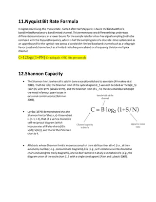
  • 1. 11.NyquistBit Rate Formula In signal processing,the Nyquistrate,namedafterHarryNyquist,istwice the bandwidthof a bandlimitedfunctionora bandlimitedchannel.Thistermmeanstwodifferentthingsundertwo differentcircumstances:asalowerboundforthe sample rate for alias-freesignal sampling(nottobe confusedwiththe Nyquistfrequency,whichishalf the samplingrate of a discrete-time system)andas an upperboundforthe symbol rate across a bandwidth-limitedbasebandchannelsuchasa telegraph lienorpassbandchannel suchasa limitedradiofrequencybandora frequencydivisionmultiplex channel C=12log2(1+PN) C=12log2(1+PN) bits per sample 12.Shannon Capacity ī‚ˇ The Shannonlimitiswhenall issaidindone exceptionallyhardtoascertain(Primakov etal. 2000). Truth be told,the Shannonlimitof the cycle diagramC_5 was notdecidedasTheta(C_5) =sqrt (5) until 1979 (LovÃĄsz1979), and the Shannonlimitof C_7 is maybe a standoutamongst the most infamousopenissuesin extremal combinatorics(Bohman 2003). ī‚ˇ LovÃĄsz(1979) demonstratedthatthe Shannonlimitof the (n,r)- Kinserchart is(n-1; r-1),that of a vertex-transitive self-reciprocal diagram(which incorporatesall Paleycharts) Gis sqrt(|V(G)|),andthatof the Petersen chart is 4. ī‚ˇ All charts whose Shannonlimitisknownaccomplishtheirabilityeitheratk=1 (i.e.,attheir autonomynumber;e.g.,consummate diagrams),k=2(e.g.,self-correlativevertex-transitive charts includingthe Paleydiagrams),orelse don'tachieve itatany estimationof k(e.g.,the diagramunionof the cycle chart C_5 witha singletondiagram) (Alonand Lubezki2006).
  • 2. 13.Impairments of Signal A transmission impairment is a property of a transmission medium which causes the signal to be degraded, reduced in amplitude, distorted or contaminated. Impairment can introduce errors into digital signals. Examples of transmission impairments are attenuation, delay distortion, and several sources of noise including, interference, thermal noise, impulse noise, and intermodulation noise. 1. Attenuation ī‚§ Attenuation is a property of the transmission medium. It measures how much energy is absorbed and/or radiated from the traveling signal due to its interaction with the transmission medium. Attenuation is measured as a function of the distance traveled through the transmission medium. A wire or cable may radiate energy when a signal travels through it. Energy is radiated at a constant rate (much smaller rate if the cable is shielded) so the longer the transmission medium the longer the signal is travelling through it and the more attenuation occurs. When a signal is transmitted through the air the signal travels in all directions (or some subset of directions with a well-designed antenna). 2. Dispersion ī‚§ Dispersion is also a property of the transmission medium. Signals with different frequencies will travel through a transmission medium with slightly different velocities. Therefore, the signal will be smeared or distorted when it reaches the destination. 3. Noise ī‚§ Noise of different types will affect a transmitting signal. Thermal noise, low amplitude random noise at predictable low amplitude (amplitude related to the temperature of the transmission medium), is caused by the thermal vibration of the molecules within the transmission medium. The difference between signal levels in a transmitted signal will generally be much larger than the amplitude of the thermal noise. Thermal noise sets a limit of how close different signal levels can be at the receiver (larger than the 2X amplitude of the thermal noise). Thermal noise will not usually be of high enough amplitude to cause the introduction of bit errors in an encoded signal (unless attenuation has been excessive)
  • 3. 14.Wave Forms A waveform is the shape and form of a signal such as a wave moving in a physical medium or an abstract representation. In many cases, the medium in which the wave propagates does not permit a direct observation of the true form. Examples ī‚ˇ Most programs show waveforms to give the user a visual aid of what has been recorded. If the waveform is of low or high height (with respect to the {display style x} x axis), the recording was most likely conducted under conditions with a low or high input volume, respectively. Sine Wave ī‚ˇ A sine wave or sinusoid is a mathematical curve that describes a smooth repetitive oscillation. A sine wave is a continuous wave. Square Wave ī‚ˇ Square waves are universally encountered in digital switching circuits and are naturally generated by binary (two-level) logic devices. They are used as timing references or "clock signals", because their fast transitions are suitable for triggering synchronous logic circuits at precisely determined intervals. Triangle Wave ī‚ˇ A triangle wave is a non-sinusoidal waveform named for its triangular shape. It is a periodic, piecewise linear, continuous real function. Like a square wave, the triangle wave contains only odd harmonics. However, the higher harmonics roll off much faster than in a square wave (proportional to the inverse square of the harmonic number as opposed to just the inverse). SawtoothWave ī‚ˇ The sawtooth wave (or saw wave) is a kind of non-sinusoidal waveform. It is so named based on its resemblance to the teeth of a plain-toothed saw with a zero rake angle.
  • 4. 15.Encoding Digital Data to Digital Signals ī‚ˇ NRZ- It refers to a variety of digital information transmission within which the binary low and high states, painted by numerals zero and one. ī‚ˇ NRZ-I- it's an information recording and transmission methodology that ensures clock synchronization. ī‚ˇ Bipolar- Here, zero is painted by no signal line and one represent positive or negative pulse. ī‚ˇ Pseudo ternary- A variation of Bipolar AMI is termed Pseudo ternary, here, one is painted no line signal and zero is positive and negative. ī‚ˇ Manchester- it's a way of transmittal bits that permits the receiver to simply synchronize with the sender. this is often a unique coding methodology from alternative strategies. ī‚ˇ Differential Manchester- it's NRZ. It modifications its sign state only if there's a change in information that differs from the previous bit.
  • 5. 16.Digital to Analog ī‚ˇ Amplitude shift keying- it's a variety of AM that represents digital knowledge as variations within the amplitude of a radio radiation. it's linear and sensitive. ī‚ˇ Frequency shift keying- Here, the modification in frequency outline in several digits. The carrier is switched between two frequencies, 1 and 0. ī‚ˇ Phase Shift Keying- it's the digital modulation technique within which the part of the carrier signal is modified by varied the circular function and cos inputs at a specific time. 17.Analog to Analog Analog-to-analog conversion, or analog modulation, is the representation of analog information by an analog signal. Modulation is needed if the medium is bandpass in nature or if only a bandpass channel is available to us. There are three ways of modulation 1. Amplitude Modulation (AM) 2.Frequency Modulation (FM) 3.Phase Modulation (PM)
  • 6. 1. Amplitude Modulation (AM) ī‚§ In AM transmission, the carrier signal is modulated so that its amplitude varies with the changing amplitudes of the modulating signal. The frequency and phase of the carrier remain the same. ī‚§ The modulation creates a bandwidth that is twice the bandwidth of the modulating signal and covers a range centered on the carrier frequency. ī‚§ The bandwidth of an audio signal (speech and music) is usually 5 kHz. Therefore, an AM radio station needs a bandwidth of 10kHz. In fact, the Federal Communications Commission (FCC) allows 10 kHz for each AM station. 2. Frequency Modulation (FM) ī‚§ In FM transmission, the frequency of the carrier signal is modulated to follow the changing voltage level (amplitude) of the modulating signal. The peak amplitude and phase of the carrier signal remain constant, but as the amplitude of the information signal changes, the frequency of the carrier changes correspondingly. ī‚§ he actual bandwidth is difficult to determine exactly, but it can be shown empirically that it is several times that of the analog signal or 2(1 β)B where β is a factor depends on modulation technique with a common value of 4. ī‚§ The bandwidth of an audio signal (speech and music) broadcast in stereo is almost 15 kHz. The FCC allows 200 kHz (0.2 MHz) for each station. This mean β = 4 with some extra guard band.
  • 7. 3.Phase Modulation (PM) ī‚§ PM transmission, the phase of the carrier signal is modulated to follow the changing voltage level (amplitude) of the modulating signal. The peak amplitude and frequency of the carrier signal remain constant, but as the amplitude of the information signal changes, the phase of the carrier changes correspondingly. ī‚§ The actual bandwidth is difficult to determine exactly, but it can be shown empirically that it is several times that of the analog signal. 18.Difference BetweenPAM, PWM & PPM PAM PWM PPM Pulse amplitude is variable constant constant Pulse width is constant variable constant Bandwidth is less high high Power of the transmitter varies Varies Remains constant Noise interface is high minimum Minimum Complex system Simpleto implement Simpleto implement
  • 8. 19.Guided & Unguided Media Telecommunication links can broadly be classed into two categories, namely, guided media (wired) and unguided media(wireless). Guided Media ī‚§ Electrical/Optical signals are passed through a solid medium (different types of cables/wires) As the path traversed by the signals is guided by the size, shape and length of the wire, this type of media is called guided media. ī‚§ E.g., Copper Unshielded Twisted Pair (UTP), Copper Shielded Twisted Pair (STP), Copper Co-axial cables, Fiber Optic Cables. Unguided Media ī‚§ Here information is transmitted by sending electromagnetic signals through free space and hence the name unguided media, as the signals are not guided in any specific direction or inside any specific medium. 1.Distance separating the end stations 2.Frequency spectrum used by the electromagnetic signals 3.Line Encoding technique used ī‚§ Based on these attributes, a wide variety of wireless PHYs and different types of antennas are used in wireless communication. The diagram given below illustrates different types of antennas typically used in wireless communication As illustrated in the diagram, antennas can be of many sizes and shapes. ī‚§ Wi-Fi, Wi-Max. 3G are example wireless networks used for internet communication.
  • 9. 20.Difference BetweenUTP and STP ī‚§ Twisted pair cables are widely used in transmitting information, especially across great distances. The twist in the wire cancels out any magnetic interference that may develop in the wiring. There are two common types of twisted pair cabling, STP and UTP. The S stands for Shielded, the U stands for Unshielded, and the TP stands for twisted pair for both. UTP STP It doesn’t have a metal foil cover It does Its less expensive thanSTP It is expensive thanUTP Grounding isnot possible It is possible Very Easy to install Easy to install Segment length is 500m 100m Very Easy Maintenance Easy Maintenance
  • 10. 21.DifferentModes of Fiber Fiber Optics is sending signals down hair-thin strands of glass or plastic fiber. The light is "guided" down the center of the fiber called the "core". The core is surrounded by a optical material called the "cladding" that traps the light in the core using an optical technique called "total internal reflection." 1.Single Mode Cable ī‚§ Single Mode fiber optic cable has a small diametral core that allows only one mode of light to propagate. Because of this, the number of light reflections created as the light passes through the core decreases, lowering attenuation and creating the ability for the signal to travel further. 2.Multi Mode Cable ī‚§ Multimode fiber optic cable has a large diametral core that allows multiple modes of light to propagate. Because of this, the number of light reflections created as the light passes through the core increases, creating the ability for more data to pass through at a given time. Because of the high dispersion and attenuation rate with this type of fiber, the quality of the signal is reduced over long distances. 22.Time DivisionMultiplexing Time-division multiplexing (TDM) is a method of transmitting and receiving independent signals over a common signal path by means of synchronized switches at each end of the transmission line so that each signal appears on the line only a fraction of time in an alternating pattern. History ī‚§ Time-division multiplexing was first developed for applications in telegraphy to route multiple transmissions simultaneously over a single transmission line. In
  • 11. the 1870s, Émile Baudot developed a time-multiplexing system of multiple Hughes telegraph machines. In 1953 a 24-channel TDM was placed in commercial operation by RCA Communications to send audio information between RCA's facility on Broad Street, New York, their transmitting station at Rocky Point and the receiving station at Riverhead, Long Island, New York. Multiplexed Digital Transmission ī‚§ In circuit-switched networks, such as the public switched telephone network (PSTN), it is desirable to transmit multiple subscriber calls over the same transmission medium to effectively utilize the bandwidth of the medium. TDM allows transmitting and receiving telephone switches to create channels (tributaries) within a transmission stream. A standard DS0 voice signal has a data bit rate of 64 kbit/s. A TDM circuit runs at a much higher signal bandwidth, permitting the bandwidth to be divided into time frames (time slots) for each voice signal which is multiplexed onto the line by the transmitter. Statistical Time-Division Multiplexing ī‚§ Statistical time-division multiplexing (STDM) is an advanced version of TDM in which both the address of the terminal and the data itself are transmitted together for better routing. Using STDM allows bandwidth to be split over one line. Telecommunication Multiplexing ī‚§ There are three types of synchronous TDM: T1, SONET/SDH, and ISDN. Plesiochronous digital hierarchy (PDH) was developed as a standard for multiplexing higher order frames. PDH created larger numbers of channels by multiplexing the standard Europeans 30 channel TDM frames.
  • 12. 23.Frequency-DivisionMultiplexing Frequency-division multiplexing (FDM) is a scheme in which numerous signals are combined for transmission on a single communications line or channel. Each signal is assigned a different frequency (subchannel) within the main channel. A typical analog Internet connection via a twisted pair telephone line requires approximately three kilohertz (3 kHz) of bandwidth for accurate and reliable data transfer. Twisted-pair lines are common in households and small businesses. Suppose a long-distance cable is available with a bandwidth allotment of three megahertz (3 MHz). When FDM is used in a communications network, each input signal is sent and received at maximum speed at all times. This is its chief asset. However, if many signals must be sent along a single long-distance line, the necessary bandwidth is large, and careful engineering is required to ensure that the system will perform properly. In some systems, a different scheme, known as time-division multiplexing, is used instead.
  • 13. 24.PSTN & POTS īƒ˜ PSTN ī‚§ PSTN (public switched telephone network) is the world's collection of interconnected voice- oriented public telephone networks, both commercial and government-owned. It's also referred to as the Plain Old Telephone Service (POTS). It's the aggregation of circuit-switching telephone networks that has evolved from the days of Alexander Graham Bell ("Doctor Watson, come here!"). īƒ˜ POTS ī‚§ Plain Old Telephone Service or POTS is the name given to the telephone system and service used during the late 19th century. It is a predecessor to more advanced telephony technologies like Public Switched Telephone Network (PSTN) and Integrated Services Digital Network (ISDN) that are used today. In this article, we will have brief look at the Plain Old Telephone Service, its general working including advantages and disadvantages of this service. What is a Plain Old Telephone Service? Now, if there are more then one Telephone User than we need more lines. Moreover, due to the analogue usage of communication in Plain Old Telephone Service (POTS), Quality of Service (QoS) is poor. Although the equipment used in Plain Old Telephone Service is simple and easy to design but the QoS and support for number of subscriber in POTS makes it a poor choice for today’s system. Thats why we moved to Public Swtiched Networks (PSTN ) and Integrated Services Digital Network (ISDN).
  • 14. 25. Wave DivisionMultiplexing (WDM) ī‚§ Wavelength-division multiplexing (WDM) is a method of combining multiple signals on laser beams at various infared (IR) wavelengths for transmission along fiber optic media. Each laser is modulated by an independent set of signals. Wavelength-sensitive filters, the IR analog of visible-light color filters, are used at the receiving end. WDM is similar to frequency-division multiplexing (FDM). In early WDM systems, there were two IR channels per fiber. At the destination, the IR channels were demultiplexed by a dichroic (two-wavelength) filter with a cutoff wavelength approximately midway between the wavelengths of the two channels. The use of WDM can multiply the effective bandwidth of a fiber optic communications system by a large factor, but its cost must be weighed against the alternative of using multiple fibers bundled into a cable. A fiber optic repeater device called the erbium amplifier can make WDM a cost-effective long-term solution.