1. The Netherlands
Almelo
(headoffice)
USA
Texas
USA
North Carolina
USA
Virginia
Spain
Barcelona
United Kingdom
Birmingham
China
Beijing
Taiwan
SingaporeMalaysia
Australia
USA
California
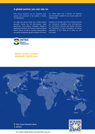
Hitec Power Protection has its worldwide head-
quarters and production & test facilities in Almelo,
The Netherlands.
Our sales and service offices are in North America
(Houston, Texas), the UK (Birmingham), Spain
(Barcelona), China (Beijing, Shanghai), Singapore,
Malaysia and Australia. We maintain a regional support
office in Taiwan, as well as numerous representatives
and agents strategically placed throughout the world.
Our efforts begin with a thought out technical
recommendation targeted to your power quality and
reliability need.
If desired, we can take care of the complete electrical
and mechanical installation and commissioning.
Our commitment continues with training, instruction
and maintenance. In case of emergency, our service
organisation is 24x7 stand by to assist you with
your needs.
A global partner you can rely on
Hitec Power Protection offices
For contact details please visit www.hitec-ups.com
partners
Global service network
Worldwide, World-class
2. Diesel UPS/CPS systems
Continuous power
Uninterruptible, continuous
and conditioned power supply
for mission critical applications
Power to rely on People to rely on
3. Introduction
Power quality and reliability for mission critical
infrastructures are an ongoing challenge in today’s
new economy. Complex systems and
processes need continuous and clean power to
maximize uptime and profitability. Uninterruptible
power is a variable in our new economy that some
have taken for granted. However, the reality of con-
tinuous and clean power is significantly
different from that perception.
Power provided by the utilities can be poor and
unreliable. This is clearly demonstrated by the
numerous power outages every year that can
damage sensitive equipment, cause financial loss
and even endanger lives. Sudden interruptions of
power can lead to serious consequences and often
irreparable damage. Consider losing data on a
bank’s computer, scrapping a batch of wafers in a
semiconductor plant, dropping a phone network
system for a metropolitan area: these are all
examples of power interruptions that are
unacceptable.
For critical applications, a continuous power supply
is a necessity. This is the world of Hitec Power
Protection. Our challenge is to provide customers
with a solution for their power quality problems
before any losses occur.
As a global supplier of uninterruptible power
supply (UPS) systems, Hitec Power Protection has
become an industry leader in providing power
quality solutions to mission critical infrastructures
and processes. Our commitment to excellence has
created an unmatched reputation and allows
companies to partner with us more easily for their
long term and ongoing power solutions.
From data centers to semiconductor fabrication,
from telecommunication sites to processing plants,
Hitec Power Protection ensures that these types of
processes and infrastructures maintain their power
reliability from the shortest interruption to even the
longest power outages.
Hitec Power Protection:
Security that goes without saying!
20
40
60
80
100
120
UTILITYFAILURES/YEAR
140
160
10 - 100 ms
100 - 500 ms
500 ms - 1 s
1 - 3 s
3 - 20 s
> 20 s
Over 280 utility failures occur each year in every industrial country
1Power to rely on People to rely on
4.
5. System description
A UPS/CPS from Hitec Power Protection is
synonymous with reliability. It filters the utility power
continuously and protects against power interrupti-
ons in a simple and effective manner. The unique
concept and design of Hitec Power Protection UPS/
CPS’ maximizes its reliability and provides the cus-
tomer with the highest available uptime. Depending
upon the size of its available fuel resource the UPS/
CPS can provide power for an indefinite time period.
The FREE-WHEEL CLUTCH is the mechanical
interface between the induction coupling/generator
and the diesel engine. The clutch allows the shaft of
the induction coupling to rotate, while the diesel
engine is at standstill.
When the diesel engine starts and the speed of
the diesel engine reaches the speed of the
induction coupling/generator, the clutch engages
automatically and the diesel engine starts to drive
the induction coupling/generator. As a result, the
diesel engine starts and ramps up completely
without load. This ensures a fast and reliable start.
In utility mode, the GENERATOR acts as a
synchronous condenser (no-load over-excited AC
motor) that maintains the speed of the outer rotor
(red) of the induction coupling. It supplies reactive
power to the load and works together with the
reactor as an active filter. In the event of a utility
power failure, the generator, first driven by the
induction coupling, then by the diesel engine,
supplies power to the critical load.
The INDUCTION COUPLING is Hitec Power
Protection’s distinctive concept and is the heart of
the UPS/CPS. The outer rotor (red) contains a
two-pole three-phase winding that accelerates the
free-spinning inner rotor (yellow) during utility mode.
When utility fails, the UPS/CPS retrieves power
from the kinetic energy of the inner rotor by energi-
zing the DC winding of the outer rotor. The amount
of energy available from the inner rotor is more than
adequate to bridge the time required for the diesel
engine to start and ramp up to full speed and
power.
Power to rely on People to rely on
The UPS/CPS system can be
supplied with the associated
SWITCHGEAR. Hitec can offer
switchgear from the manufacturer
of your choice.
3
6. The UPS/CPS is simple to operate by the digital or
analog Human Machine Interface (HMI). A complete
overview of the condition of the UPS/CPS is
provided. Remote access can be established either
through hard wiring, serial links or via Internet.
The REACTOR (CHOKE) uncouples the utility power
from the load. The reactor, in conjunction with the
generator, acts as a continuous filter that allows the
UPS/CPS to maintain the output voltage within the
strictest tolerances.
The microprocessor-based controller DiCon
performs the CONTROL of the UPS/CPS. The
DiCon is a universal controller for generator
voltage, active and reactive power, diesel speed
and induction coupling control. Its universal design
is configured by software to match all possible
systems and configurations.
The DIESEL ENGINE sits idle in utility mode. The
engine is pre-heated and pre-lubricated to assure a
fast and reliable start. Once utility power fails or
falls outside of its tolerance, the diesel is issued a
start command and ramps up to full speed and
power.
In the meantime the induction coupling supplies the
needed power to the critical load. Total transfer
time is approximately 5...10 seconds.
4
7. Four basic principles
Hitec Power Protection’s unique concept for
assuring uninterruptible, continuous and clean
power rests on four basic principles. Each of them
contributes to the unprecedented advantages of
our UPS/CPS system over traditional static UPS
systems with batteries.
1. UPS/CPS = static UPS + standby generator
A traditional battery UPS system is composed of a
rectifier, batteries and inverter. The UPS provides
temporary power via its batteries and then transfers
the critical load to a standby generator that
supplements power for longer outages.
This type of system requires large areas of interior
space that are very costly. Additionally, the energy
losses generated in the battery UPS need
extensive room ventilation and the batteries
require location in a conditioned room at constant
temperature. These dedicated cooling systems
contribute heavily to the life cycle costs.
Our UPS/CPS system integrates this traditional
system into one. The advantages are clear. Fewer
components mean lower installation costs and
inherently higher reliability. A Hitec UPS/CPS has a
considerably smaller footprint than a battery UPS
system with standby generator. This offers
tremendous space and weight savings.
When utility power is lost, the UPS/CPS retrieves
stored kinetic energy from its induction coupling to
support the critical load until the diesel
engine takes over. This principle eliminates
environmentally unfriendly and unreliable battery
systems.
Hitec UPS/CPS:
Simple, sure and reliable
1
2
3
5
4
6 7
Q3
Q2Q1
Utility Load
Xa
X"d
(Choke)
Reactor
Xc
Xb
Supply side Battery UPS + standby generator
Supply side Hitec CPS system
1
2
3
5
4
6 7
Q3
Q2Q1
Utility Load
Xa
X"d
(Choke)
Reactor
Xc
Xb
Supply side Battery UPS + standby generator
Supply side Hitec CPS system
The simplicity of our UPS/CPS vs. a battery UPS configuration
1 Double conversion power converter (static UPS)
2 Batteries (VRLA)
3 Standby generator
4 Harmonic filter
Power to rely on People to rely on 5
1
3
4
2
8. 6
2. Line-interactive system
Hitec Power Protection UPS/CPS systems are
line-interactive and run in parallel with the utility
power, a logical choice since, paradoxically, for the
majority of time the utility supply is of a high
quality and reliability. A line-interactive system
takes advantage of these qualities by connecting
the UPS/CPS in parallel, as opposed to series, with
the utility supply.
The UPS/CPS is like a lifeguard that is always alert
and ready to jump in if necessary when utility power
fails or falls outside specified tolerances. There is
no conversion of electrical energy flowing from
utility to the critical load, making our UPS/CPS the
most efficient and reliable system available.
A traditional battery UPS continuously converts
electrical energy through rectifiers and inverters
that provide a common point of failure and reduce
its efficiency. When factoring in the energy
needed to operate a battery UPS’ airconditioning
requirement, a true realization of energy savings
associated with the UPS/CPS system can be
derived and realized throughout the life of your
project.
Line-interactive: Life guarding
your mission critical applications
7
3
2
erator
The highly efficient line-interactive system... ...compared to the traditional double conversion concept
2
3
5
4
6 7
Q3
Q2Q1
Utility Load
Xa
X"d
(Choke)
Reactor
Xc
Xb
Supply side Battery UPS + standby generator
Supply side Hitec CPS system
9. 3. Active filter
The combination of the reactor (choke) and
synchronous generator acts as a filter to clean the
incoming utility supply. This is achieved by setting
the position of the tapping so that the equivalent
circuit impedances of the generator and the reactor
give a zero impedance path (X”d + Xc = 0).
Hitec’s UPS/CPS system does not utilize any
power electronics to generate, condition or convert
the output voltage, so it does not produce any
harmonics itself, unlike conventional UPSs. Instead
it acts as a harmonic filter to both supply and load
borne harmonics. Additionally, the generator
supplies the reactive power drawn by the load. The
result is that the utility power factor is always close
to unity.
Outstanding qualities of the active filter:
• Compensation of utility voltage deviations
• Filtering of utility borne harmonic voltages
• Filtering of load borne harmonic currents
• No UPS/CPS borne harmonic currents / voltages
• Input power factor close to unity (>0.98)
Rotating filter: No load - utility
interdependencies
1
2
3
5
4
6 7
Q3
Q2Q1
Utility Load
Xa
X"d
(Choke)
Reactor
Xc
Xb
Supply side Battery UPS + standby generator
1
2
3
5
4
6 7
Q3
Q2Q1
Xa
(Choke)
Reactor
Xb
Supply side Battery UPS + standby generator
Supply side Hitec CPS system
Electrical equivalent diagram of the active filter
1 Voltage peaks
2 Frequency variations
3 Brown-outs / voltage drops
4 Black-outs / outages
5 Radio frequency interferences
6 Harmonic distortions
7 Continuous quality power
7
A Hitec UPS/CPS acts as a filter for all sorts of utility disturbances
10. 4. Battery-free solution
The UPS/CPS system from Hitec Power Protection
uses stored kinetic energy to bridge the diesel start
time upon a utility power failure. It is a battery-free
concept, which was invented and patented by
Hitec Power Protection in 1969 and continues to be
in successful commercial operation throughout the
world.
Some typical battery associated
weaknesses illustrated
Battery-free: Problem-free
Lifetime expectancy
Battery lifetime theoretically is 5 to 15 years;
practically they last for 3 to 5 years. Economic
lifetime of a battery UPS is 10-15 years; a Hitec
UPS/CPS last for 25 years!
Temperature sensitivity
Battery capacity decreases significantly at low
temperatures, while lifetime halves every 10°C
(18°F) above 20°C (68°F). Installation in
conditioned rooms is a must!
Environmental effects
Batteries contain environmentally harmful
materials; used batteries are chemical waste.
Disposal costs are high!
Maintenance
The only sound method to monitor battery
capacity is discharge testing, which is time
consuming (battery must be disconnected from
the UPS)!
10
20
30
40
50
60
70
25/77 30/86 35/95 40/104 45/113 50/122 55/131
80
90
100
110
Temperature (oC/oF)
LIFETIMEEXPECTANCY(%)
Theoretical Lifetime
Expectancy (Years)
3
5
7
9
10 155
ACTUALLIFETIME(YEARS)
A battery’s lifetime expectancy drops fast at higher ambient
temperatures
The difference between theoretical and actual battery lifetime!
The heart of a battery UPS is also its weak link. The
huge batteries required constitute a sizeable
problem that, to the user’s frustration, only
becomes apparent after several years of operation.
Battery related issues you won’t face with a Hitec UPS/CPS:
8
11. System operation
Utility mode
In utility mode, the reactor and the generator
function as an active filter that prevents any
disturbance from the utility reaching the critical
load. The generator runs as a motor and drives the
outer rotor of the induction coupling at a speed of
1500/1800 rpm. Through excitation of the two pole
three-phase winding in the outer rotor, the inner
rotor reaches a speed of 3000/3600 rpm relative to
the outer rotor. As a result, kinetic energy is stored
in the inner rotor. The outer rotor of the induction
coupling is isolated from the standby diesel engine
by the free-wheel clutch.
Change-over to diesel mode
In case of a power interruption or an unacceptable
deviation in the supply of utility power, the circuit
breaker Q1 opens. The induction coupling’s
DC windings are then excited, thus allowing a
transfer of stored kinetic energy from the inner rotor
to the outer rotor. The speed of the generator
remains constant at 1500/1800 rpm.
Simultaneously, the diesel engine starts and ramps
up to 1500/1800 rpm in less than 2 seconds, after
which the free-wheel clutch engages automatically.
For the next few seconds the diesel engine
together with the induction coupling drive the
generator to ensure a proper supply of power to the
critical load. Within 5..10 seconds the diesel engine
is the sole provider of power to the load.
Time
0
n
3n
Speed(rpm)
Dependent system load
Q3
Q2Q1
9Power to rely on People to rely on
1 2 3 4 1
1 13 42
1
1
Q3
Q2Q1
1 2 3 4 1
2
2
12. Diesel mode
When in diesel mode, the three-phase winding of
the outer rotor is re-energized causing the inner
rotor to ramp up to 3000/3600 rpm again. The
speed of the diesel engine is monitored and
digitally controlled to ensure a constant output
frequency. While in diesel mode, the output
frequency remains within narrow tolerances, even if
the system encounters high load steps, since the
induction coupling will be utilized to support the
diesel engine.
Back to utility mode
After utility power has stabilized, the UPS/CPS
synchronizes with utility power and closes Q1. The
diesel engine then ramps down to 1450/1750 rpm,
and as a result the free-wheel clutch disengages.
Simultaneously, the generator returns to its motor
operation and maintains the speed of the outer
rotor of the induction coupling at 1500/1800 rpm.
The diesel engine will continue to run for a short
time in a no-load condition to cool down. After the
diesel has completed its cool-down run it will shut
down and return to standby mode.
Q3
Q2Q1
Q3
Q2Q1
10
1 2 3 4 1
1 2 3 4 1
3
4
3
4
Critical and non-critical load
A single brief utility power failure can have
disastrous consequences for many mission critical
applications, i.e. data center computers, Internet
servers, etc. Other components that make up these
critical environments can be without power for
several seconds, i.e., airconditioning, lighting, etc.
One single UPS/CPS system can provide power to
both types of loads in our dual output
configuration.
The generator of a Hitec UPS/CPS system is
always sufficiently overrated to ensure adequate
short circuit capacity to clear any downstream
faults quickly, while also being able to regulate the
output voltage closely during a utility brown-out.
When in diesel mode this excess power can be
utilized to supply non-critical loads. To enable this
option, the diesel engine rating is increased to
supply both the critical and non-critical loads. This
configuration is known as dual output.
The non-critical load is not typically connected to
the UPS/CPS output. When utility fails, the UPS/
CPS supplies uninterrupted clean power to the
critical load while the diesel engine ramps up.
Once the diesel engine has reached normal
operating conditions, the non-critical load will be
switched to the output of the UPS/CPS system by
closing Q6 (Q5 has opened in the meantime).
Within approximately 10 seconds the non-critical
load will be energized again.
With the dual output configuration you can
optimize your reliability, design and achieve a
reduced footprint. Our dual output configuration is
the most common design manufactured for our
UPS/CPS systems.
Dual output:
Optimal use of resources!
A dual output system optimally capitalizes UPS/CPS’ capacity
1 Total power rating 2 Critical load rating 3 Total power rating
Q3
Q2
Critical load
Non-critical load
Q6
Q5
Q1
1 2 3
13. 11
The simplicity of the UPS/CPS design offers
unique characteristics and numerous
advantages. As the exclusive worldwide supplier,
Hitec Power Protection is able to bundle several
critical aspects together into one reliable system
that distinguishes itself from the traditional
battery UPS / standby generator combination.
Therefore, a UPS/CPS system from Hitec Power
Protection is the first and only choice!
1. Battery-free solution!
No batteries are used in a Hitec UPS/CPS system;
instead kinetic energy is used to bridge diesel start
time. The system is not sensitive to the variety of
problems associated with the use of batteries.
2. UPS/CPS = static UPS + standby generator
Hitec Power Protection’s UPS/CPS concept is
simple and efficient when compared to the battery
UPS + standby generator concept: harmonic
filters, rectifiers, battery banks, inverters, static
switches, standby generator, etc ... The Hitec
Power Protection UPS/CPS integrates all these
functions into one system.
3. Line-interactive without power electronics
The unique line-interactive concept of a Hitec
Power Protection UPS/CPS leads to significant
benefits. The CPS does not perform a double
energy conversion that battery UPS’ must execute
even when reliable utility power is available. No
power electronics are utilized; instead Hitec
incorporates a synchronous generator to supply
the load.
Leading Lagging
90 % 100 %
0.98
1.0
110 %
Dieselmode
(utilityoutoftolerance)
Dieselmode
(utilityoutoftolerance)
Utility voltage
Powerfactor
Power factor is always close to unity (>0.98)
Features & benefits
Battery-free solution
• No re-investments every 3-5 years for new
batteries
• No need for a dedicated climate controlled
battery room
• Reduced floor space requirements
• No battery disposal costs every 3-5 years
(chemical waste!)
• No need for costly spill containment systems
UPS/CPS = Static UPS + standby generator
• Fewer components thus inherently more
reliable design
• Higher MTBF and availability figures
• Lower installation and commissioning costs
• Smaller overall dimensions and floor space
requirements
• Only 1 output ACB required at your supply
switchboard
• Simplicity; easier to operate and maintain
Line-interactive without power electronics
• No double energy conversion; higher efficiency
• No power conversion; higher MTBF and
availability figures
• No generation of harmonic currents / voltages
• Long technical lifetime compared to systems
with power electronics
(25 compared to 15 years)
Reactor + generator = active filter
• High short circuit output capacity. The system
does not need to go to by-pass (use the utility)
to clear an output fault
• Reactive output power supplied by generator
(pf > 0.98)
• Dips and spikes on the utility voltage are blocked
• Compensation of prolonged deviations of the
utility voltage
• Filtering of utility borne harmonic voltages
• Filtering of load side borne harmonic currents
The unprecedented advantages of UPS/CPS
Power to rely on People to rely on
14. 4. Reactor + generator = active filter
The magnetically coupled tapped reactor (choke)
and generator act as an active filter, efficiently clea-
ning the utility voltage from all disturbances before
reaching the load.
Additionally, our generator is able to provide a high
short circuit current of up to 14x its nominal output
current. This is another key advantage over
traditional based systems. If a short circuit occurs
downstream from the UPS/CPS, the UPS/CPS will
clear the fault while remaining in utility mode.
Traditional battery UPS systems are forced to
transfer to bypass and hope the utility clears the
fault. If utility power is not available during this
event, the load will be unprotected and susceptible
to a load loss. The fact that a Hitec UPS/CPS does
not transfer to bypass in this situation should not be
underestimated.
Conclusion
Hitec Power Protection’s UPS/CPS has various
advantages over traditional UPS systems. These
advantages include reduced footprint, lower
installation costs, annual utility savings, elimination
of climate control systems, elimination of
environmentally unfriendly batteries, reduced
structural weight on your building, elimination of
compatibility problems with standby generators,
higher reliability and elimination of large
capital expenditures associated with battery
replacements.
Lowest life cycle cost - guaranteed!
400 800 1000 1200 1600 1800
Output Rating (kVA)
100
80
60
40
20
0
1100
880
660
440
220
0
FLOORSPACE(M
2
)
Battery UPS
+ Standby Generator
Hitec CPS System FLOORSPACE(FT
2
)
Floor space requirement of a Hitec UPS/CPS
versus a battery UPS
Higher output, smaller footprint, no battery
replacements, less structural weight, higher
efficiency and elimination of airconditioning
requirements result in the Hitec UPS/CPS’ lower
life cycle cost.
Price estimation model
Hitec Power Protection has developed a model to
estimate the life cycle cost for both a Hitec
UPS/CPS system as well as for a battery UPS +
standby generator. The model not only considers
the initial investment, but also re-investments and
yearly operating costs. We would be more than
pleased to show you the difference!
Various lease options
To substantiate our statement of lowest life cycle
cost even further, we can offer you a variety of lease
options.
Operational lease:
Electrical energy ensured by Hitec Power
Protection up to the highest reliability at a fixed
price. We supply, install, and maintain the
UPS/CPS system. You pay us per month and leave
your worries to us!
Financial lease:
Hitec Power Protection can offer you a tailored
financial lease option. For a fixed amount per year,
we can install a Hitec UPS/CPS system at your
facility. Leave the responsibility of maintenance and
service to us. They can all be included in the lease
contract!
With the variety of options to obtain a Hitec Power
Protection UPS/CPS, coupled with lower life cycle
costs, it is easier than ever to address your power
protection needs at the highest possible return on
your investment!
12
15. Unit configuration features
UPS/CPS systems can be delivered in a variety of
configurations. Each configuration can be tailored
to your specific needs; from a single module
UPS/CPS to a distributed redundant dual output
configuration.
Single Systems
Single Output UPS/CPS System
In a single output configuration all components
(generator, induction coupling, diesel engine and
reactor) are rated to provide continuous and clean
power to the critical load.
Dual Output UPS/CPS System
To ensure sufficient short circuit capacity and
guaranteeing narrow voltage tolerances, the
UPS/CPS’ generator is overrated. This excess
power can be used to supply non-critical loads.
The diesel engine’s rating must then be increased
to supply both the critical and non-critical loads.
This configuration is known as the dual output
system. When the utility fails, the UPS/CPS will
protect the critical load. As soon as the diesel
engine has started and has stabilized the critical
load, the UPS/CPS then assumes the non-critical
load by closing Q6. Virtually no additional cost or
space is required.
Medium Voltage System
For higher power ratings, medium voltage (MV)
systems can be offered. Hitec Power Protection
offers two types of medium voltage configurations.
The first option incorporates a low voltage power
module with an additional step up transformer; the
other incorporates a MV power module. Circuit
breakers and the reactor will always be configured
at the medium voltage level.
Single output, dual output and MV systems are
available in a variety of configurations.
Critical load
Q3
Q1
Non-critical load
Q2
Utility
MV
LV
Q6
Q5
Critical load
Q3
Q1
Non-critical load
Q2
Utility
Q6
Q5
CPS Dual output
Critical load
Q3
Q1 Q2Utility
13Power to rely on People to rely on
CPS Dual output
Dual output
UPS/CPS units
(LV and MV):
Removes the need for
separate gensets for
non-critical loads.
Low voltage (LV)
UPS/CPS units:
Simplest means of providing
complete conditioning and
protection to all critical
loads.
Medium voltage
(MV) UPS/CPS
units:
Simple means of providing
complete conditioning and
protection to large loads
where LV solutions are not
ideal.
16. 14
Parallel / Parallel Redundant
Configurations
Parallel Configuration
For load requirements over our largest single
module unit (3,000 kVA) parallel configurations can
be designed for increased output. Paralleling units
is also considered when redundancy is required.
The most common redundant configuration is ‘N + 1’.
When two units are required to supply the critical
load, another unit will be installed to provide back
up should a unit fail. The total number of units,
which can be installed in parallel, is limited by the
total output current/short circuit current. Currents
over 6,000 A are not practical, i.e. total output
power is limited to approx. 4,000/5,000 kVA at
380/480 V.
Critical load
2Q1
Non-critical load
2Q2
Q6
Q3
1Q1 Q4
Utility
1Q2
Q5
3Q1 3Q2
CPS Dual output
Parallel configuration
Master-Slave Configuration
An alternative configuration for two parallel units is
the master-slave configuration. This option is more
appropriate if two groups of critical outputs are
separated without a common point of coupling. The
control system maintains synchronization between
both units ensuring that the tying breaker (Q13)
can be closed at any time due to failure or
maintenance. No common point of failure is
present.
Critical load
Q3
Q1
Non-critical load
Q2
Q6
Q5
Critical load
Q3
Q1
Non-critical load
Q2
Utility
Q6
Q5
Q13
A-system
B-system
Master-slave configuration
17. Cross-Link Configuration
In the parallel configuration, the total critical load is
connected to one output bus. In situations where
there are two separate independent loads a
cross-link (or Q29) configuration can be used. As in
a parallel system the redundancy is N+1 over the
total amount of units, but during normal operation
the system acts as two independent parallel
systems. The redundancy however is shared bet-
ween the two systems and in case one of the two
parallel systems is overloaded closing the Q29
breaker will make use of the surplus of power
available in both of the systems. When in Q29
mode a output bus failure occurs it will be limited to
the bus causing the fault; the other system will be
disconnected by opening Q29.
Redundancy is only shared between critical loads;
non-critical loads do not have a cross-link
connection.
The cross-link therefore virtually eliminates single
points of failure in the bus-structure.
The limitations of the system are equal to that of a
parallel system.
Cross-link configuration
Critical load
Non-critical load
(option)
Non-critical load
(option)
A2Q1 A2Q2
AQ3
A1Q1
AQ4
Utility
BQ4
A1Q2
B1Q1 B1Q2
Critical load
B2Q2B2Q1
Q29
BQ3
AQ6
AQ5
BQ6
BQ5
18. Systems configurations features:
Advantages
System configuration Characteristics
Parallel Redundant (PR)
Simplest and most compact means of achieving
redundancy between UPS units and of
supporting very large or multiple loads.
Master - Slave (MS) Eliminates a common UPS output bus-bar.
Cross - Link (CL)
Virtually eliminates the common output bus-bar.
On multi-UPS unit systems, far less UPS units
required to achieve required redundancy than in
an MS system.
Isolated - Parallel (IP)
No common output bus-bar due to additional tie
breakers and isolating chokes.
Efficient and flexible use of the system redundant
capacity.
Isolated - Redundant (IR)
No common output bus-bar due to separation of
loads and UPS unit outputs.
Fewer breakers and chokes required than in an
IP system.
Distributed Redundant (DR)
No common output bus-bar due to separation of
loads and UPS unit outputs.
Fewer breakers and chokes required than in an
IP system.
Efficient and flexible use of the system redundant
capacity.
19. Power to rely on People to rely on 15
Isolated Redundant Configuration
Traditionally, a parallel redundant configuration
would be used if redundancy were required. With
an isolated redundant configuration, redundancy is
created on the basis of standard single units.
All individual units support their individual critical
loads. In an ‘N+1’ configuration, these systems
have one redundant unit as a backup. The backup
unit normally operates in a no-load condition. In the
event that one unit fails or is taken off-line, the
critical loads are automatically transferred to the
redundant unit (closing Q3A) via closed transition
instead of going to bypass.
Additionally, the non-critical load can be
connected to the redundant unit utilizing the
available UPS/CPS power. In case of maintenance
or failure of one module, the non-critical load will be
transferred back to the utility supply and your
critical load will be maintained.
Isolated redundant configuration
Utility
1Q1 1Q2
1Q3
1Q6
1Q5
Line interactive choke Isolating choke
Star
bus
Critical
load 1
Non-critical
load 1
2Q1 2Q2
2Q3
2Q6
2Q5
Line interactive choke Isolating choke
Star
bus
Critical
load 2
Non-critical
load 2
3Q1 3Q2
3Q3
3Q6
3Q5
Line interactive choke Isolating choke
Star
bus
Critical
load 3
Non-critical
load 3
nQ1 nQ2
nQ3
nQ6
nQ5
Line interactive choke Isolating choke
Star
bus
Critical
load n
Non-critical
load n
Isolated parallel system configuration
Isolated Parallel System Configuration
The isolated parallel system configuration
combines the fault-tolerance of redundant systems
with the load sharing capabilities of a parallel
system.
The isolated parallel configuration connects multiple
units together, thereby creating redundancy, while
maintaining isolation between units at the same
time. Active power can then be shared between
units, while load faults will be kept isolated from
each other. A fault on one load will therefore not
influence other loads.
1Q3
1Q1
Non-critical load C
(Optional)
1Q2
Utility
1Q6
1Q5
Critical load A
2Q3B
2Q1
Non-critical load A
2Q3A
2Q2
Utility
2Q6
2Q5
Critical load B
3Q3B
3Q1
Non-critical load B
3Q3A
3Q2
Utility
3Q6
3Q5
Redundant
bus-bar
All circuit breakers in this configuration need to be
rated to each unit’s nominal output current. This
configuration can be used for much higher power
ratings as compared to the parallel redundant
configurations.
20. 16
Distributed Redundant Configuration
In the isolated redundant configuration, the
redundant unit is normally supplementing a
non-critical load or running at no load at all. This
can be overcome with the distributed redundant
design.
Distributed redundant systems are normally
designed for ‘N+1’ redundancy. No single module
is assigned as a redundant unit. Instead, this role is
shared equally among all modules.
In the event of a single unit failure, its load will be
shared proportionately over the remaining units.
The load transfers are accomplished through
automatic transfer switches (ATS). The advantages
are the elimination of single point failures and equal
load sharing among all units.
Distributed redundant configuration
1Q3
1Q1
Non-critical load A
1Q2
Utility
1Q6
Non-critical load B
Critical
load A1
Critical
load B1
Critical
load B2
Critical
load C1
Critical
load C2
Critical
load A2
1Q5
Redundant bus-bar
A B C
2Q3
2Q1 2Q2
Utility
2Q6
2Q5
ATS
ATS
ATS
ATS
Non-critical load C
3Q3
3Q1 3Q2
Utility
3Q6
3Q5
ATS
ATS
CPS Dual output
QMS remote monitoring
Hitec Power Protection offers QMS, a powerful
software tool for the monitoring, supervision and
maintenance support of UPS/CPS systems. QMS
is a multi-purpose user-friendly software tool that
runs on a pc with Windows®. The status, event
history and electrical parameters are gathered,
stored and conveniently arranged on the pc screen
for easy reading and printing.
Easy access
The pc running the QMS software can be
connected to the UPS/CPS system either at site
through a dedicated serial link, remotely through a
modem connection, or over the Internet.
Detailed information
The program provides detailed information on the
UPS/CPS’ status to make supervision easier.
Voltage and current readings, circuit breaker status,
operating hours, number of diesel starts, diesel
running time, and various other data are shown.
The software not only provides the user with real
time information but also provides a historical
overview of state changes and events over the last
half year. This overview is shown either as a list of
events, or as a “mimic movie.” The software is a
very powerful tool to help users and technicians
understand the UPS/CPS operation and thereby
greatly extends the operational, service and
maintenance possibilities of your UPS/CPS system.
Many of these readings can also be displayed as a
strip chart of events, which is especially useful
when viewing multi-module systems.
Monitoring your UPS/CPS systems at a glance with QMS software
21. Installation & commissioning
To install and commission a Hitec UPS/CPS system
is relatively easy and simple. It is very similar to
installing a standby generator.
When comparing a UPS/CPS system to the
installation and commissioning of a battery UPS +
standby generator, a Hitec UPS/CPS eliminates the
installation of a battery UPS, batteries, harmonic
filters and all the inter-connecting electrical wiring
and synchronizing equipment.
• The power module comes pre-mounted on a
robust base frame. As an option, split frames can
be supplied to aid any site-specific difficulties
with lifting and installing.
• Mounting engine exhaust, fuel and cooling
systems are identical to the installation works
required for a standby generator.
• Room ventilation is similar for a Hitec UPS/CPS
system as for a standby generator.
• The associated switchgear is standard
equipment, avoiding any special installation and
commissioning procedures.
• The human machine interface provides easy and
clear access to all system parameters. It is a
powerful information tool for a simple & fast
commissioning of the UPS/CPS system.
Customer support
The Hitec Power Protection name is synonymous
with reliability, quality and excellent service. We
believe that the best technology is only as good as
the service that supports it.
We have therefore established a network of
qualified service organizations.
The main service organizations can
• Provide Help Desk Services - available
24 x 7 x 365 - for operational questions, remote
monitoring / support, troubleshooting, etc.
• Provide remote monitoring and diagnostic
support. Our service department can access
your UPS/CPS system through the Internet or a
modem connection, thus assisting with
operational issues, offering maintenance advice,
providing troubleshooting, etc.
• Provide training programs at various skill levels
for the operation and maintenance of our
systems.
• Rent containerized UPS/CPS units up to
1,000 kVA for disaster recovery, high-risk
maintenance periods, temporary power needs,
etc.
We can arrange the
complete installation of
your UPS/CPS systems
Power to rely on People to rely on 17
22. Technical specifications
Input:
Input voltage: LV 380...480 V 50/60 Hz
MV Up to 24 kV 50/60 Hz
Voltage tolerance: +/- 10%
Power factor: > 0.98
Output:
Output voltage: LV 380...480 V 50/60 Hz
MV Up to 24 kV 50/60 Hz
Voltage deviation: +/- 1%
Voltage asymmetry: < 2%
Harmonic distortion: < 3.5%
(with linear load)
Harmonic filtering: > 95%
(in both directions)
Frequency deviation: < 0.5% ... 2.5%
Short circuit current: Up to 14x
Nominal Current
Nominal power factor: 0.8
System:
Efficiency: Up to 97%
Crest factor: ≥ 3
RFI level: Class A (EN 55.011)
Some examples of available models
Other:
Color scheme:
RAL 7032 (Light Grey): Base frame & panels
RAL 5012 (Blue): Induction coupling
& generator
Diesel engine: Manufacturers’
standard
Environmental (standard):
Degree of protection: IP21
(or higher as option)
Operating altitude: < 150 m above
sea level
Ambient temperature: 0...40 °C (32 ... 104 °F)
Options:
• Remote monitoring via Internet or modem
connection
• Other non-standard environmental conditions,
power ratings, voltages etc.
• Silencing canopies
• Medium voltage configurations
• Containerized designs
• Vibration monitoring
• Bearing vibration monitoring
Contact Hitec for other options
Max. output rating (kVA) Approx. dimensions*
l x w x h
50 Hz 60 Hz 50 Hz 60 Hz mm (inch) kg (lbs)
600 500 600 1.000 1.200 5,900 x 1,600 x 2,100 8.000
(230 x 65 x 85) (17.700)
1200 1.000 1.200 2.000 2.400 7,200 x 1,900 x 2,100 13.000
(285 x 75 x 85) (28.700)
1800 1.700 1.800 2.250 2.500 8,600 x 1,900 x 2,400 21.500
(340 x 75 x 95) (47.400)
2200 2.000 2.200 2.900 3.000 8,600 x 1,900 x 2,400 24.750
(340 x 75 x 95) (54.600)
* Dimensions and weights for power module; excluding switchgear and control panel
18
All data in this brochure is for information and is subject to change without prior notice. No rights can be obtained from the contents of this brochure. Data provided in our offerings prevail at all times.
Type
UPS/CPS
Critical load Critical + non-critical load
Approx.
weight)*