
Recommended
More Related Content
Similar to 6-failures.pptx
Similar to 6-failures.pptx (20)
Recently uploaded
Recently uploaded (20)
6-failures.pptx
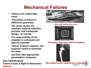
- 1. Chapter 8 - Mechanical Failures • Failures are undesirable event. • Prevention of failure is difficult to guarantee. • The usual causes are improper material selection, process, and inadequate design, or misuse. • It is responsibility of the engineer to anticipate and plan for possible • failure. If failure happens, the engineer needs to assesses its cause • and then take appropriate preventative measures. 1 Ship-cyclic loading from waves. Computer chip-cyclic thermal loading. Hip implant-cyclic loading from walking. Did a Metallurgical Failure Cause a Night to Remember (titanic)
- 2. Chapter 8 - 2 Fracture mechanisms • Ductile fracture – Accompanied by significant plastic deformation • Brittle fracture – Little or no plastic deformation – Catastrophic
- 3. Chapter 8 - 3 Ductile vs Brittle Failure Very Ductile Moderately Ductile Brittle Fracture behavior: Large Moderate %AR or %EL Small • Ductile fracture is usually more desirable than brittle fracture! Adapted from Fig. 8.1, Callister & Rethwisch 8e. • Classification: Ductile: Warning before fracture Brittle: No warning
- 4. Chapter 8 - 4 • Ductile failure: -- one piece -- large deformation Figures from V.J. Colangelo and F.A. Heiser, Analysis of Metallurgical Failures (2nd ed.), Fig. 4.1(a) and (b), p. 66 John Wiley and Sons, Inc., 1987. Used with permission. Example: Pipe Failures • Brittle failure: -- many pieces -- small deformations
- 5. Chapter 8 - 5 • Resulting fracture surfaces (steel) 50 mm particles serve as void nucleation sites. 50 mm From V.J. Colangelo and F.A. Heiser, Analysis of Metallurgical Failures (2nd ed.), Fig. 11.28, p. 294, John Wiley and Sons, Inc., 1987. (Orig. source: P. Thornton, J. Mater. Sci., Vol. 6, 1971, pp. 347-56.) 100 mm Fracture surface of tire cord wire loaded in tension. Courtesy of F. Roehrig, CC Technologies, Dublin, OH. Used with permission. Moderately Ductile Failure • Failure Stages: necking s void nucleation void growth and coalescence shearing at surface fracture
- 6. Chapter 8 - 6 Moderately Ductile vs. Brittle Failure Adapted from Fig. 8.3, Callister & Rethwisch 8e. cup-and-cone fracture brittle fracture
- 7. Chapter 8 - 7 Brittle Failure Arrows indicate point at which failure originated Adapted from Fig. 8.5(a), Callister & Rethwisch 8e.
- 8. Chapter 8 - 8 • Intergranular (between grains) 304 S. Steel (metal) Reprinted w/permission from "Metals Handbook", 9th ed, Fig. 633, p. 650. Copyright 1985, ASM International, Materials Park, OH. (Micrograph by J.R. Keiser and A.R. Olsen, Oak Ridge National Lab.) Polypropylene (polymer) Reprinted w/ permission from R.W. Hertzberg, "Defor-mation and Fracture Mechanics of Engineering Materials", (4th ed.) Fig. 7.35(d), p. 303, John Wiley and Sons, Inc., 1996. 4mm • Transgranular (through grains) Al Oxide (ceramic) Reprinted w/ permission from "Failure Analysis of Brittle Materials", p. 78. Copyright 1990, The American Ceramic Society, Westerville, OH. (Micrograph by R.M. Gruver and H. Kirchner.) 316 S. Steel (metal) Reprinted w/ permission from "Metals Handbook", 9th ed, Fig. 650, p. 357. Copyright 1985, ASM International, Materials Park, OH. (Micrograph by D.R. Diercks, Argonne National Lab.) 3mm 160mm 1mm (Orig. source: K. Friedrick, Fracture 1977, Vol. 3, ICF4, Waterloo, CA, 1977, p. 1119.) Brittle Fracture Surfaces
- 9. Chapter 8 - 9 Concentration of Stress at Crack Tip Adapted from Fig. 8.8(b), Callister & Rethwisch 8e.
- 10. Chapter 8 - 10 Engineering Fracture Design r/h sharper fillet radius increasing w/h 0 0.5 1.0 1.0 1.5 2.0 2.5 Stress Conc. Factor, K t = • Avoid sharp corners! s Adapted from Fig. 8.2W(c), Callister 6e. (Fig. 8.2W(c) is from G.H. Neugebauer, Prod. Eng. (NY), Vol. 14, pp. 82-87 1943.) r , fillet radius w h smax smax s0
- 11. Chapter 8 - 11 Crack Propagation Cracks having sharp tips propagate easier than cracks having blunt tips • A plastic material deforms at a crack tip, which “blunts” the crack. deformed region brittle Energy balance on the crack • Elastic strain energy- • energy stored in material as it is elastically deformed • this energy is released when the crack propagates • creation of new surfaces requires energy • Crack propagates if crack-tip stress (sm) exceeds a critical stress (sc) ductile
- 12. Chapter 8 - 12 Impact Testing final height initial height • Impact loading: -- severe testing case -- makes material more brittle -- decreases toughness Adapted from Fig. 8.12(b), Callister & Rethwisch 8e. (Fig. 8.12(b) is adapted from H.W. Hayden, W.G. Moffatt, and J. Wulff, The Structure and Properties of Materials, Vol. III, Mechanical Behavior, John Wiley and Sons, Inc. (1965) p. 13.) (Charpy)
- 13. Chapter 8 - 13 Influence of Temperature on Impact Energy Adapted from Fig. 8.15, Callister & Rethwisch 8e. • Ductile-to-Brittle Transition Temperature (DBTT)... BCC metals (e.g., iron at T < 914ºC) Impact Energy Temperature High strength materials (sy > E/150) polymers More Ductile Brittle Ductile-to-brittle transition temperature FCC metals (e.g., Cu, Ni)
- 14. Chapter 8 - 14 • Pre-WWII: The Titanic • WWII: Liberty ships • Problem: Steels were used having DBTT’s just below room temperature. Reprinted w/ permission from R.W. Hertzberg, "Deformation and Fracture Mechanics of Engineering Materials", (4th ed.) Fig. 7.1(a), p. 262, John Wiley and Sons, Inc., 1996. (Orig. source: Dr . Robert D. Ballard, The Discovery of the Titanic.) Reprinted w/ permission from R.W. Hertzberg, "Deformation and Fracture Mechanics of Engineering Materials", (4th ed.) Fig. 7.1(b), p. 262, John Wiley and Sons, Inc., 1996. (Orig. source: Earl R. Parker, "Behavior of Engineering Structures", Nat. Acad. Sci., Nat. Res. Council, John Wiley and Sons, Inc., NY, 1957.) Design Strategy: Stay Above The DBTT!
- 15. Chapter 8 - 15 Fatigue Adapted from Fig. 8.18, Callister & Rethwisch 8e. (Fig. 8.18 is from Materials Science in Engineering, 4/E by Carl. A. Keyser, Pearson Education, Inc., Upper Saddle River, NJ.) • Fatigue = failure under applied cyclic stress. • Stress varies with time. -- key parameters are S, sm, and cycling frequency smax smin s time sm S • Key points: Fatigue... --can cause part failure, even though smax < sy. --responsible for ~ 90% of mechanical engineering failures. tension on bottom compression on top counter motor flex coupling specimen bearing bearing
- 16. Chapter 8 - 16 Adapted from Fig. 8.19(a), Callister & Rethwisch 8e. Types of Fatigue Behavior • Fatigue limit, Sfat: --no fatigue if S < Sfat Sfat case for steel (typ.) N = Cycles to failure 103 105 107 109 unsafe safe S = stress amplitude • For some materials, there is no fatigue limit! Adapted from Fig. 8.19(b), Callister & Rethwisch 8e. case for Al (typ.) N = Cycles to failure 103 105 107 109 unsafe safe S = stress amplitude
- 17. Chapter 8 - 17 • Crack grows incrementally typ. 1 to 6 a s ~ increase in crack length per loading cycle • Failed rotating shaft -- crack grew even though Kmax < Kc -- crack grows faster as • s increases • crack gets longer • loading freq. increases. crack origin Adapted from Fig. 8.21, Callister & Rethwisch 8e. (Fig. 8.21 is from D.J. Wulpi, Understanding How Components Fail, American Society for Metals, Materials Park, OH, 1985.) Rate of Fatigue Crack Growth m K dN d a
- 18. Chapter 8 - 18 Improving Fatigue Life 2. Remove stress concentrators. Adapted from Fig. 8.25, Callister & Rethwisch 8e. bad bad better better Adapted from Fig. 8.24, Callister & Rethwisch 8e. 1. Impose compressive surface stresses (to suppress surface cracks from growing) N = Cycles to failure moderate tensile sm Larger tensile sm S = stress amplitude near zero or compressive sm --Method 1: shot peening put surface into compression shot --Method 2: carburizing C-rich gas
- 19. Chapter 8 - 19 Creep Sample deformation at a constant stress (s) vs. time Adapted from Fig. 8.28, Callister & Rethwisch 8e. Primary Creep: slope (creep rate) decreases with time. Secondary Creep: steady-state i.e., constant slope e/t). Tertiary Creep: slope (creep rate) increases with time, i.e. acceleration of rate. s s,e 0 t
- 20. Chapter 8 - 20 • Occurs at elevated temperature, T > 0.4 Tm (in K) Adapted from Fig. 8.29, Callister & Rethwisch 8e. Creep: Temperature Dependence elastic primary secondary tertiary
- 21. Chapter 8 - Creep Failure • Failure: along grain boundaries. applied stress g.b. cavities From V.J. Colangelo and F.A. Heiser, Analysis of Metallurgical Failures (2nd ed.), Fig. 4.32, p. 87, John Wiley and Sons, Inc., 1987. (Orig. source: Pergamon Press, Inc.) 21
- 22. Chapter 8 - Prediction of Creep Rupture Lifetime • Estimate rupture time S-590 Iron, T = 800ºC, s = 20,000 psi time to failure (rupture) function of applied stress temperature L t T r ) log 20 ( Time to rupture, tr 3 10 x 24 ) log 20 )( K 1073 ( r t Ans: tr = 233 hr Adapted from Fig. 8.32, Callister & Rethwisch 8e. (Fig. 8.32 is from F.R. Larson and J. Miller, Trans. ASME, 74, 765 (1952).) 103 T(20+log tr)(K-h) Stress (10 3 psi) 100 10 1 12 20 24 28 16 data for S-590 Iron 20 24 22
- 23. Chapter 8 - Estimate the rupture time for S-590 Iron, T = 750ºC, s = 20,000 psi • Solution: 23 23 Adapted from Fig. 8.32, Callister & Rethwisch 8e. (Fig. 8.32 is from F.R. Larson and J. Miller, Trans. ASME, 74, 765 (1952).) 103 L (K-h) Stress (10 3 psi) 100 10 1 12 20 24 28 16 data for S-590 Iron 20 24 3 10 x 24 ) log 20 )( K 1023 ( r t Ans: tr = 2890 hr time to failure (rupture) function of applied stress temperature L t T r ) log 20 ( Time to rupture, tr
- 24. Chapter 8 - 24 • Sharp corners produce large stress concentrations and premature failure. SUMMARY • Engineering materials not as strong as predicted by theory • Flaws act as stress concentrators that cause failure at stresses lower than theoretical values. • Failure type depends on T and s : -For simple fracture (noncyclic s and T < 0.4Tm), failure stress decreases with: - increased maximum flaw size, - decreased T, - increased rate of loading. - For fatigue (cyclic s: - cycles to fail decreases as s increases. - For creep (T > 0.4Tm): - time to rupture decreases as s or T increases.
- 25. Chapter 8 - 25 http://www.tms.org/pubs/journals/jom/9801/felkins-9801.html Titanic article: ANNOUNCEMENTS Boiler: :http://www.youtube.com/watch?v=PsSVfAg1kRg