1. TURBO OPTIC 3
Functional description of
user Interface
Art.-No: 10020253
Issue: from V3.0 up (1104)
2. Imprint
II TURBO OPTIC 3 - User Interface ID 10020253
All trademarks are the acknowledged property of their owners.
Though appropriate care has been used in compiling this User Manual,
errors and omissions cannot be ruled out completely due to continu-
ously ongoing development.
Because of technical developments, HOMMELWERKE GmbH retains
the right to make technical changes without obligation of notification.
No liability will be accepted in the event of damage resulting from non-
compliance with the information contained herein.
No part of this User Manual may be reproduced in any way (by print,
photocopying, microfilm or any other technique), nor may it be proc-
essed, duplicated or disseminated with the help of electronic systems
without prior written consent of the HOMMELWERKE GmbH.
Date: 17. Juni 2005
HOMMELWERKE GmbH
Alte Tuttlinger Str. 20
D-77056 VS-Schwenningen
Tel. + 49 7720/ 602 - 0
Fax + 49 7720/ 602 - 123
e-mail: info@hommelwerke.de
3. Contents
TURBO OPTIC 3 - User Interface I
Contents
1 System description .................................................................... 1
1.1 General/Commissioning...................................................... 1
1.1.1 Scope of performance ..................................................... 1
1.1.2 System requirements ...................................................... 2
1.1.3 Installation of the TURBO OPTIC software ..................... 3
1.1.4 Switching the measuring system on and off.................... 7
1.2 User interface....................................................................... 9
1.2.1 General............................................................................ 9
1.2.2 Overview window........................................................... 11
1.2.3 Detail window ................................................................ 17
1.2.4 Operating elements ....................................................... 21
1.2.5 User levels..................................................................... 24
1.2.6 Configuring the user interface ....................................... 25
1.3 Menu Overview................................................................... 31
1.3.1 File menu....................................................................... 31
1.3.2 Edit menu ...................................................................... 32
1.3.3 View menu..................................................................... 33
1.3.4 Workpiece contour menu .............................................. 34
1.3.5 Tools menu.................................................................... 34
1.3.6 Statistics menu.............................................................. 34
1.3.7 Machine Control menu .................................................. 35
1.3.8 Extras menu .................................................................. 36
1.3.9 Help menu ..................................................................... 37
1.4 System dialog boxes ......................................................... 37
1.4.1 Licence file TURBO OPTIC........................................... 37
1.4.2 Connecting to the measuring machine.......................... 38
1.4.3 Support.......................................................................... 38
1.5 Archiving data.................................................................... 39
1.5.1 General.......................................................................... 39
1.5.2 Directory structure TO3 ................................................. 39
2 Measuring.................................................................................. 41
2.1 Prerequisites ...................................................................... 41
2.1.1 Important ....................................................................... 41
2.2 Performing a measurement .............................................. 41
2.2.1 Starting a measurement ................................................ 41
4. Contents
II TURBO OPTIC 3 - User Interface ID 10020253
2.2.2 Measuring individual characteristics ..............................41
2.2.3 Serial measurement.......................................................41
2.2.4 Cancelling the measurement .........................................42
2.2.5 Status messages ...........................................................42
2.3 Representation of the measurement results ...................43
2.3.1 General ..........................................................................43
2.3.2 Result list .......................................................................43
2.4 Analysis graphic.................................................................44
2.4.1 Overview........................................................................44
2.4.2 Diameter ........................................................................44
2.4.3 Length............................................................................45
2.4.4 Radius............................................................................46
2.4.5 Angle..............................................................................46
3 Test program management......................................................48
3.1 New test program...............................................................48
3.1.1 General ..........................................................................48
3.1.2 Test program folder .......................................................48
3.1.3 Contour scanning...........................................................48
3.2 Opening the test program .................................................51
3.3 Converting old test programs ...........................................52
3.3.1 General ..........................................................................52
3.3.2 Work steps.....................................................................52
3.4 Editing the test program....................................................53
3.4.1 Test program header tab ...............................................53
3.4.2 Defining characteristics..................................................58
3.5 Printing the test program and results ..............................59
3.5.1 General ..........................................................................59
3.5.2 Starting a printout ..........................................................60
3.5.3 Online printing................................................................65
3.6 Example of creating and using a test program ...............65
3.6.1 Creating a new test program .........................................65
3.6.2 Creating and describing test characteristics..................66
4 Index...........................................................................................70
5. General/Commissioning
TURBO OPTIC 3 - User Interface 1
1 System description
1.1 General/Commissioning
1.1.1 Scope of performance
The TURBO OPTIC software package offers the user extensive op-
tions for measurement and evaluation of diameters, lengths, geometry,
form and position.
The workpiece is probed automatically opto-electronically according to
the silhouette principle. The complete workpiece contour can be
evaluated quickly and precisely by the high measuring resolution per
single measured value.
The data of the outside contour of the workpiece are recorded during
the rotational movement for rotation measurements. Any standard
measurement functions can be combined depending on the measuring
program and then follow an optimised, automatic measuring run.
The creation of test programs and display and further processing of the
measuring results takes place simply and intuitively by means of a
graphic user interface under Windows XP.
Several wizards support the user in programming and positioning. The
offered used levels provide application-related access rights for differ-
ent operators and avoid operating errors.
The following table shows all the available test characteristic groups
and their icons. Depending on the issued licence and the set machine
characteristics, not always all types are available. Detailed information
about the individual test characteristics can be found in the documen-
tation Description of the Test Characteristics.
The test characteristic groups are selectable in a toolbar (test charac-
teristic bar) in the working window of TURBO OPTIC. (see subsection
Test characteristic bar , page 23 )
Icon Test characteristic group
Positions, Length
Diameter
Angle
Radius
Roundness
Run-out
Total run-out
Rotational position
Eccentricity
6. System description
2 TURBO OPTIC 3 - User Interface ID 10020253
Icon Test characteristic group
Cylindricity
Thread
Form deviation
Straightness
Parallelism
Symmetry
Part axis
Calculations
External gauges
Service and commissioning
1.1.2 System requirements
The TURBO OPTIC software was developed for the non-contact shaft
measuring systems CONTOUR as well as AMV and WMS.
The following system requirement must be met for operation of the
TURBO OPTIC software:
Requirement Minimum Recommended
Operating
system
Windows 2000, SP4 Windows XP SP2
Internet Ex-
plorer
Version 5.5 Version 6, SP1
.NET Frame-
work
Version 1.1
MDAC Version 2.6 Version 2.8
TURBO
OPTIC
BWMS 1.045 and SWMS 2.1.13
Processor Pentium 3 (800 MHz),
512 Mbytes RAM,
Screen resolution
1280x1024
Pentium 4,
512 Mbytes RAM,
Screen resolution
1280x1024
The software requirements are checked and installed if necessary dur-
ing installation. The service packs are not on the installation CD and
must be installed beforehand. In addition all the security updates and
patches available from Microsoft must be installed.
7. General/Commissioning
TURBO OPTIC 3 - User Interface 3
1.1.3 Installation of the TURBO OPTIC software
1.1.3.1 Important notes
Administrator rights are necessary for installation.
The TURBO OPTIC software is installed on the measuring system ini-
tially by HOMMELWERKE GmbH.
The TURBO OPTIC software should only be re-installed after a system
crash!
Contact your responsible partner at HOMMELWERKE GmbH in any
case to be able to save data!
Close all applications on your PC before re-installing/updating TURBO
OPTIC !
Saved test programs and device data are not deleted in case of a re-
installation or update!
1.1.3.2 Operating languages
The TURBO OPTIC software is available in several program lan-
guages. All the currently available language versions are installed in
the software installation.
After starting the software, the desired operating language can be se-
lected from the list of available languages in the Start screen. Then the
user logs in by name and the software changes automatically to the
previously selected language.
If you want to activate another operating language, the software must
be exited completely and restarted.
If the Automatic Login option has been set for a user (Extras/User Ac-
counts menu or Extras/Settings/Start Behaviour menu) this function
must first be deactivated so that the software displays the start screen
and the language setting is available!
1.1.3.3 Initial installation
Proceed as follows to install:
1. Start the Windows operating system on the measuring system PC.
2. Insert the CD-ROM with the TURBO OPTIC software in the CD-ROM
drive.
3. The TURBO OPTIC installation program starts automatically. All installa-
ble options of the CD are listed. The offered options are installed in order.
Uninstallable options are shaded grey and deactivated.
Attention!
Note
8. System description
4 TURBO OPTIC 3 - User Interface ID 10020253
4. The installation wizard also checks necessary system components and
installs or updates these as required.
Click on [Install] to start the installation programs of the individual system
components. The system may be restarted (or several times) for this.
5. The installation program selects the path C:TO3 as a directory for the in-
stallation. It is recommended to keep this directory and select the Full In-
stallation type.
6. In the next step, all the path settings set by the installation programs are
displayed:
9. General/Commissioning
TURBO OPTIC 3 - User Interface 5
All successfully set entries are marked dark green, missing files or folders
on the other hand red.
7. This is followed by creation of a user with administrator rights in TURBO
OPTIC. This step is optional if a user with administrator rights has already
been found in an existing TO3 installation during an update.
A name must be entered for the user. A password can but need not be
assigned.
8. In the next step all path settings set by the installation program for the
Hommelwerke component Statistics output are displayed:
10. System description
6 TURBO OPTIC 3 - User Interface ID 10020253
All successfully set entries are marked dark green, missing files or folders
on the other hand red.
9. This is followed by creation of the TO3 user in the Windows operating
system. Restricted rights are defined by a system directive on the system
for this user. This is meant to prevent normal users being able to change
the system settings.
As a directory right on the installation directory All have full access is set.
The installation is completed by clicking on [Exit].
1.1.3.4 Installing an update
Updates are only possible from older to newer versions of the TURBO
OPTIC or to same versions in a different language.
Installation of an update runs exactly the same as initial installation.
The existing installation is found and updated. If necessary, you are
then prompted to restart the operating system.
11. General/Commissioning
TURBO OPTIC 3 - User Interface 7
1.1.4 Switching the measuring system on and off
1.1.4.1 Switching on the measuring system
Switch the measuring system on with the main switch and wait until
Windows has started fully.
Start the TURBO OPTIC software by clicking on the program icon of
TURBO OPTIC in the "Start" menu (Start bar):
1.1.4.2 Start page - User login
The software shows the start screen first.
Figure 1-1: Start screen TURBO OPTIC
Dialog topic Description
User login Perform your user login here. To do so, enter the user
name and the password.
Language-
setting
Here you can activate another program language directly
after starting the software.
Connection to
the measuring
machine
To make a connection to a measuring machine, the name
of the measuring machine must be entered in the input
box. The name of the measuring machine most recently
used is entered as a default and the option for connecting
to the measuring machine is set.
If no connection is to be made, the No connection function
must be activated. The measuring machine can be con-
nected later in the File menu.
Program start
TURBO OPTIC
12. System description
8 TURBO OPTIC 3 - User Interface ID 10020253
Dialog topic Description
Licence infor-
mation
Display of information about the current licence as well as
the software version.
Most recently
used measur-
ing programs
The most recently used measuring programs are listed in
this list in case of repeated software starts.
If you select one of these programs, the software changes
to this selected software automatically the next time you
start it.
Confirm all entries with [OK]. The software is started, the connection to
the selected measuring machine made and this initialised. The suc-
cessful connection is then displayed in green in the status bar. If an er-
ror occurs during initialisation, an appropriate message is output. The
software opens the view with the test program header first.
Starting here, you can access all other program sections and functions
according to the set user rights.
1.1.4.3 Switching off the measuring system
To switch off the form measuring system, the TURBO OPTIC software
must be exited first.
Press the [Logoff user xyz] button from any program section or exe-
cute the "Exit" command in the "File" menu alternatively to do this. If
you only log the user off, you can then log in again in the Start screen
with another user name.
The following security prompt appears:
Figure 1-2: Exit TURBO OPTIC for Windows
yes All changes are saved, the TURBO OPTIC program is exited
and you return to the start screen
no The changes are not saved. TURBO OPTIC is exited.
Cancel TURBO OPTIC is not exited. The changes are not saved.
Then run down the PC and switch off the measuring machine's main
switch.
13. User interface
TURBO OPTIC 3 - User Interface 9
1.2 User interface
1.2.1 General
The TURBO OPTIC software is based on the user-friendly user inter-
face of Microsoft Windows. This guarantees a flexibly adaptable de-
sign of the measurement and evaluation functions and the screen rep-
resentations. The terminology used is based largely on the language
used in Microsoft Windows. Common shortcuts and processing rou-
tines (Copy, Paste from clipboard etc.) are identical.
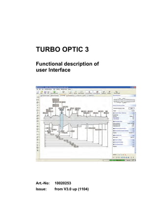
Figure 1-3: Screen layout of TURBO OPTIC
Window area Description
Overviewwindow
with tabs (centre
left)
The overview window takes up the larger part of the
working area. It serves to display various views of the
test program and the measurement results.
Detail window
(right)
More detailed information about a selected test char-
acteristic are displayed in the Detail view in the right
hand part of the program window (overview graphic,
current test characteristic, test characteristic parame-
ters, detail contour, result details...). The detail view
can be switched between parameter and result repre-
sentation.
Description of the user interface elements
Dialog boxes
Dialog boxes expect different entries from the user. The input boxes
are usually organised topically and are characterised as follows:
14. System description
10 TURBO OPTIC 3 - User Interface ID 10020253
Tabs
Tabs divide the dialog boxes into several pages. Every tab has its own
title. Clicking on this tab title activates the desired tab card and dis-
plays it in the foreground for editing.
Text boxes
Text boxes serve for free entry of texts or numbers (pre-formatted if
necessary).
Drop-down list boxes
List boxes contain a list of available selection possibilities. Click on the
small box with the black triangle to drop down the list. Then select the
desired option.
Checkboxes
Checkboxes serve to indicate whether the respective function is active
or inactive. Click on the box briefly when you want to change the status
of the function.
Option boxes
Option boxes represent mutually exclusive functions, i.e. only one of
several options can be selected or active at one time.
15. User interface
TURBO OPTIC 3 - User Interface 11
1.2.2 Overview window
1.2.2.1 Test program header tab
Settings are defined in the test program header tab which are valid for
the whole test program.
In addition, comments, descriptions and images or graphics can be
stored for more exact characterisation of the workpiece.
After opening a test program this tab is displayed first as a standard.
Figure 1-4: Test program header
16. System description
12 TURBO OPTIC 3 - User Interface ID 10020253
1.2.2.2 Characteristics list tab
This tab is available to users with authorisation to create test pro-
grams.
It shows a tabular view of all the characteristics defined in the test pro-
gram with all the important information about these characteristics
(name, type, group, nominal value, tolerance limits etc.).
All displayed information can be edited and changed directly in the ta-
ble.
All the information is displayed clearly in the Detail window for the re-
spective selected characteristic.
The characteristics list can be sorted in ascending or descending order
of the column contents by clicking on the column headers. This sorting
is adopted for all views.
Defective characteristics are highlighted in colour in a list.
The columns to be displayed can be defined in the program settings.
Figure 1-5: Characteristics list
1.2.2.3 Program contour tab
This tab shows the workpiece contour scanned by the measuring ma-
chine and the positions of the characteristics defined in the test pro-
gram.
After a measurement the icons (flags) of the test characteristics are
coloured according to the measurement result.
Measuring range and probing diameter are displayed for the respec-
tively selected characteristic.
Users with authorisation for creating test programs can create and
change test characteristics with graphic support.
17. User interface
TURBO OPTIC 3 - User Interface 13
Figure 1-6: Program contour
Position Function / Description
by flag or mea-
suring range
display
Display of the test characteristic name
other position Display of position co-ordinates (display mode depend-
ing on the setting in the View menu or in the context
menu of the right mouse button)
by a changeable
element
Changing the appearance of the mouse pointer (Touch
mode)
During graphic manipulation of the characteristic (left
mouse button pressed) the corresponding numeric value
is displayed on the mouse pointer.
any with ALT
key pressed
The co-ordinates of the position on the mouse pointer
are always displayed.
any with Shift
key pressed
Nothing displayed on the mouse pointer.
Action Description
Click in free area The current selection (marking) of characteristics is
cancelled.
Click on a flag The characteristic is selected (cancellation of the pre-
vious selection). When measurement results are avail-
able every further click on the flag switches between
the views Test characteristic parameters and Result
details.
Functions of the
mouse pointer
Functions left
mouse button
18. System description
14 TURBO OPTIC 3 - User Interface ID 10020253
Action Description
pressed CTRL
key + click on a
flag
Every further flag is added to the current selection.
Click on flag and
move flag
The flag is selected and can then be moved. However,
this is only possible if the Manual positioning of flags
option has been activated in the program settings.
Click on measur-
ing range and
move/change the
measuring range
The test characteristic is selected in the program con-
tour and the measuring range is displayed. When the
mouse button is pressed, the range can be moved
and/or its size changed.
Attention!
If the measuring range is moved for a length position
to the extent that the nominal value is outside the
measuring range afterwards, this nominal value is set
to the centre of the new measuring range.
Pressing and
dragging in the
free window area
Drag open a zoom window and zoom in when releas-
ing the mouse button.
Pressing and
dragging open +
ALT key in any
area
Drag open a zoom window and zoom in on releasing
the mouse button even if the mouse pointer is over a
flag.
Pressing and
dragging open +
Shift key (over
flag)
The flags within the opened area are added to the cur-
rent selection.
Action Description
Click in free area A context menu for the contour graphic is displayed
(re-open display, Zoom, Export)
Click on an al-
ready selected
flag
A context menu for the characteristic is displayed (Co-
py, Delete...)
Click on an un-
marked flag
The flag is selected, the previous selection is can-
celled.
A context menu for the characteristic is displayed (Co-
py, Delete...)
Keep pressed
and move
The whole section of the picture can be moved (mouse
pointer changes to a grabbing hand).
The picture section can be enlarged and reduced by turning the mouse
wheel. The current mouse pointer position provides the reference
which retains its screen position.
Functions right
mouse button
Functions mouse
wheel
19. User interface
TURBO OPTIC 3 - User Interface 15
1.2.2.4 Program tree tab
The program tree represents the graphic display of the dependence
chain for the current, selected characteristic. On the one hand all the
characteristics are displayed on which the current characteristic itself
depends. On the other hand all characteristics are displayed simulta-
neously which depend directly on the current characteristic.
With the aid of this program tree the user can get a visual impression
of the dependencies in the test program and navigate quickly between
the dependent characteristics.
After a measurement, the characteristics are coloured according to the
measurement result. In this way, reference characteristics are above
all easy to locate.
Figure 1-7: Dependence chain for a characteristic in the program tree
1.2.2.5 Result list tab
In the result list the measurement results of the current measurement
are displayed. You can select which information is to be displayed here
in the program settings.
There is a choice of measured value, rated value, tolerance limits, tol-
erance evaluation, some statistical information and a bar graph.
20. System description
16 TURBO OPTIC 3 - User Interface ID 10020253
Figure 1-8: Result list
1.2.2.6 Bar tab
The bar graph offers an alternative look at the measurement results.
Every result is represented by a coloured bar. The length of the re-
spective bar indicates approximately where a measured value is in the
tolerance zone.
Figure 1-9: Bar graph
21. User interface
TURBO OPTIC 3 - User Interface 17
1.2.2.7 Run chart tab
In the run chart tab the results of all the measurements made with the
current program are shown in a simple diagram. Tolerance limits and
warning limits are drawn and the measured value is coloured accord-
ing to its result. Only one test characteristic at a time can be selected
for viewing.
The display is reset when exiting the software or changing the test
program.
Figure 1-10: Run chart
1.2.3 Detail window
1.2.3.1 Navigation
The toolbar for navigating between the test characteristics and switch-
ing the Detail window view is located at the bottom of the Detail win-
dow.
Figure 1-11: Detail window - Toolbar
Icon Description
Meas-
urement
Starts a measurement of the selected characteristic.
If several characteristics are selected, measurement of these
characteristics is started. References necessary for the meas-
urement are resolved automatically.
22. System description
18 TURBO OPTIC 3 - User Interface ID 10020253
Icon Description
Cut:
Cuts out the selected characteristics and puts them in the clip-
board.
Copy:
Copies the selected characteristics to the clipboard.
Paste:
Pastes the characteristics in the clipboard into the test program.
Delete:
Deletes the selected characteristics from the test program.
There is no security prompt. Dependent characteristics cannot
be deleted and remain in the test program. The test program
must then be adapted.
Note:
Accidental deletion can be cancelled with the Undo function.
Switch view:
Switches the Detail view between parameter and result repre-
sentation
Previous characteristic:
Go to the previously viewed test characteristic
Next characteristic:
Go to the next characteristic (after using the Previous character-
istic function)
Start characteristic list:
Go to the first characteristic in the characteristics list
Back in the characteristics list:
Go to the previous characteristic in the characteristic list
Forwards in the characteristics list:
Go to the next characteristic in the characteristics list
End characteristic list:
Go to the most recent characteristic in the characteristics list
Undo:
Reverses a change to a test characteristic or the test character-
istics list. (corresponds to the menu command Edit/Undo)
Restore:
Restores an undone change.
1.2.3.2 Overview graphic
A small display of the whole workpiece contour appears right at the top
of the Detail window. If the program contour tab is selected in the
23. User interface
TURBO OPTIC 3 - User Interface 19
overview window, the current picture section is selected in the over-
view graphic. This can be changed by dragging open a rectangle (with
the mouse).
After a measurement the contour is coloured according to the overall
result.
The overview graphic is always displayed regardless of which Detail
window view is switched on.
Figure 1-12: Overview graphic
1.2.3.3 Current test characteristic
This view is only available to users with authorisation to create test
programs. Switch the detail window view to parameter representation if
necessary.
The parameters for the test characteristic are grouped according to
topics (e.g. measuring range, references, rated dimension, tolerances,
extended settings etc.). The information is displayed as soon as a cha-
racteristic is selected in any tab.
Figure 1-13: Current test characteristic - Details
24. System description
20 TURBO OPTIC 3 - User Interface ID 10020253
The individual groups can be opened and closed by clicking on the
group title to avoid having to display all the information the whole time.
The groups with the important characteristics are opened automatically
when changing to the next characteristic. All other groups are closed.
The current status can be fixed by clicking on the pin needle in the left
hand margin of every group header, i.e. there is no automatic opening
and closing of this group.
The parameters are input either by direct text entry, by clicking or by
selecting a list. The selection lists only offer respective permissible va-
lues.
After changing a parameter this entry is checked and other parameters
are adapted if necessary. This can lead to other parameters being
shown or hidden depending on whether they can be used in the current
combination.
Defective parameters or parameters which are still to be set are marked
in colour. Invariable parameters (e.g. tolerance values in ISO tolerances)
are marked by a blue parameter name.
For parameters which need references to other characteristics, only
permissible reference characteristics are displayed in the selection lists.
When opening the selection list ( ) all other characteristics are hid-
den temporarily in the program contour. The reference characteristic
can also be selected in the graphic by clicking on the desired flag.
By clicking on the arrow icon ( ) next to a reference, you can switch
directly to the selected reference characteristic.
By clicking the asterisks ( ) you can start creating a new reference
characteristic.
1.2.3.4 Detail contour
Switch over the detail window view to result representation if neces-
sary.
The contour evaluated for the characteristic and additional information
such as nominal value, actual value and tolerance range are displayed
in the graphic. The display of the additional information can be acti-
vated or deactivated by clicking on the buttons underneath the graphic.
To highlight details you can switch to a root section display in which
relevant details are represented with heavy accentuation of height.
This is done by clicking the right mouse button in the graphic and se-
lection in the context menu or with the button above the graphic.
If a characteristic has been calculated from several part contours, you
can switch between these by clicking on the arrow icons above the
graphic. For some characteristics, e.g. roundness, you can switch be-
tween filtered contour and unfiltered raw contour. The type and num-
ber of the displayed part contour is displayed above the graphic.
A detail contour view is opened in the overview window by clicking on
the icon for zoom. This shows the same characteristic but is independ-
ent with regard to the settings.
Reference charac-
teristics
25. User interface
TURBO OPTIC 3 - User Interface 21
Figure 1-14: Detail contour
1.2.3.5 Result details
Switch over the detail window view to result representation if neces-
sary.
The test characteristic name and type, tolerance evaluation and other
in information are displayed in this result list. Unlike the Result List tab
in the overview window, more details and a detailed descriptive test in
the case of errors are displayed here. In the program settings it can be
defined which information is to be displayed in this list.
Figure 1-15: Result details
1.2.4 Operating elements
1.2.4.1 Mouse and keyboard operation
All the functions or menu commands can be activated with the mouse
or PC keyboard.
The mouse provides the most comfortable operation of the software.
The following input options are distinguished:
• Click or click on by briefly pressing the left mouse button (mark, select
and object)
• Click by pressing the right mouse button (open the context menu)
• Double click by briefly pressing the left mouse button twice (e.g. open a
dialog window by double clicking on an object
• Drag & Drop, i.e. moving marked elements with the mouse with the left
mouse button pressed
However, TURBO OPTIC can also be operated with the PC keyboard.
For most menu items and commands, shortcuts (e.g. Ctrl+A) are
specified in the menu.
26. System description
22 TURBO OPTIC 3 - User Interface ID 10020253
Otherwise use the key combination ALT + the underscored letter of the
desired menu title or command. Then move to the desired command
with the cursor keys. With the Enter key ↵ confirm your selection.
Commands for management and editing of test programs, statistic
outputs and for controlling the measuring machine are available in the
main menu. Important commands are also accessible by buttons in the
toolbar and in the context menu (right mouse button) of the respective
view.
In some menus various functions can be activated or deactivated by
clicking or optionally selected. If the functions concerned are active,
this status is displayed by a preceding checkmark.
1.2.4.2 Toolbar
Various buttons are arranged in the main toolbar which are identified
by icons and a description. This toolbar is available in all program sec-
tions of TURBO OPTIC and does not change.
Figure 1-16: Main toolbar TURBO OPTIC:
Icon Command Key-
board
Description
New... Ctrl + N • Create new test program
If the currently loaded program is
changed a security prompt appears to
save the changes.
After basic initialisation (at successful
connection to the measuring machine)
workpiece contour scanning begins.
Open Ctrl + O • Open saved test program
The current test program is closed first
(with prompt to save).
Save Ctrl + S • Save current test program
Print Ctrl + P • Print current view
(with selection of printer).
Start mea-
surement
F5 A complete measurement is started
with the current test program.
Cancel
measure-
ment
F6 The current measurement is aborted.
Zoom 1:1 The zoom settings of the displayed
graphic are changed so that the work-
piece contour is fit optimally into the
display window.
27. User interface
TURBO OPTIC 3 - User Interface 23
Icon Command Key-
board
Description
Note:
Flags of test characteristics may now
be outside the visible area!
Zoom all The zoom settings of the displayed
graphic are changed so that the work-
piece contour and all flags of test
characteristics are visible in the dis-
play window.
Zoom se-
lection
Changes the zoom factor so that the
flags of selected characteristics and
the measuring range of the focussed
characteristic fit optimally in the win-
dow.
Without
positions
Flags of the test characteristic group
length positions are hidden in the
graphic.
Without ro-
tational po-
sitions
Flags of the test characteristic group
rotational positions are hidden from
the graphic.
Show all All hidden characteristics are shown
again here.
Analysis Switches over to the Analysis Graphic
mode.
Logoff
<Name>
The currently logged in user is logged
off and the software returns to the start
screen.
1.2.4.3 Test characteristic bar
The test characteristic bar provides all the buttons for creat-
ing the test characteristics. Every button is assigned to a
test characteristic group. By clicking on the button a sub-
menu opens with all the test characteristics available in this
group.
The selected test characteristic is entered in the detail win-
dow for further specification.
A description of the buttons can be found in subsection
Scope of performance , page 1 .
28. System description
24 TURBO OPTIC 3 - User Interface ID 10020253
1.2.4.4 Status bar
In the status bar the user gets context-related information about the
command inputs which have been executed. Messages are output and
the status of the test program displayed in addition.
Figure 1-17: Status bar
Description (from left to right):
Field in status bar Description
Message area (example:
measurement running)
Display of short information texts for uncritical
events
Call error log
On arrival of incoming error messages from
the measuring machine, this button can open
the log of received error messages.
Measurement time
Duration of the most recent measurement in
[s]
or
Test program status
green: no error in the test program
red: the digit in the box indicates the number
of errors in the test program. The next defec-
tive characteristic is moved to by clicking on
the box in the case of several errors.
Network status
An active connection to the measuring ma-
chine is signalled by flashing and a digit is also
displayed as a status code for the status of the
measuring machine.
Measuring machine
green: display of the measuring machine's
name
red: there is no connection to the measuring
machine
1.2.5 User levels
Depending on the authorisations of the logged in users, views are hid-
den which this user cannot use. This gives two operating modes:
User level Functions
Measurement only In this mode the number of available functions, tabs and
views is restricted to measurement of the necessary
scope.
Create test pro-
gram
All the functions are views necessary for creating test
programs are available.
Status bar
29. User interface
TURBO OPTIC 3 - User Interface 25
1.2.6 Configuring the user interface
1.2.6.1 Overview
With the Extras/Settings menu a dialog box is called with which the
user interface settings can be made. Both view options and program
functions can be adapted.
Figure 1-18: Dialog box for setting the user interface
All settings are combined topically in groups. These groups are shown
on the left hand side of the dialog box in a pop-up tree structure.
Select a setting from the tree on the left to display the setting options
for this topic as a list in the window on the right.
Every line in this list represents the name and value of a setting. When
a line is selected, a short description of this setting option appears di-
rectly underneath the list.
The type and method how a setting can be changed depends on their
type. For some settings a text or a number must be entered, for others
you can select from a list of possible values or a support dialog box is
displayed.
Every setting is assigned a standard value. If a setting deviates from
its standard value, this is identified by a name written in bold print.
To accept the changed settings, press the [Transfer] button (the chan-
ges the become immediately effective, the dialog box stays open) or
exit the dialog box with [OK].
Note:
These accepted changes can no longer be undone [Cancel]!
Press the [Standard values] button to reset all setting options to the
standard values assigned at the factory. You can decide in a subse-
quent security prompt whether all the settings or only those of the cur-
Changing set-
tings
Save settings
Reset settings
30. System description
26 TURBO OPTIC 3 - User Interface ID 10020253
rently displayed group are to be reset to the standard values. In addi-
tion this action can be aborted at this point.
1.2.6.2 Starting behaviour of the interface
Setting Description
Most recently used
measuring ma-
chine
Display of the name of the most recently used measur-
ing machine
This machine is displayed in the start screen and used
for automatic login.
Connection at the
start
Define whether a connection is to be made with the
most recently used measuring machine at the start of
the software.
This setting can be deselected again during login in the
start screen.
Load most recent
file
If this option is active, the most recently used test pro-
gram is loaded at the start (only for automatic login).
Automatic login Entry of user who is logged in automatically at the start
of the software without entering a password
1.2.6.3 View options
Various view options can be agreed respectively for the different tabs
in the overview and detail windows.
For example, the columns to be displayed in the list can be defined,
colours for the result display selected and formats for units defined.
General view options
The general view options apply for all subordinate groups.
Setting Description
Selection colour Colour used for highlighting a currently selected test
characteristic
Coverage strength
of the selected col-
our
Degree of transparency of the selected colour
Error colour Colour for marking defective test characteristics
Number of decimal
places
Determines the number of decimal places for test char-
acteristic parameters and measurement results
Rotation angle for-
mat degrees-
minutes-seconds
Switches on the display of angle rotation in the degrees-
minutes-seconds format instead of the normal decimal
display.
Separating lines in
the characteristics
editor
A grid network is displayed in the view Test Characteris-
tic Parameters.
Display concealed
test characteristic
types
Historic (outdated) test characteristic types which are
not to be used as standard are activated.
31. User interface
TURBO OPTIC 3 - User Interface 27
View options for the characteristic list
Setting Description
Font Font for displaying the characteristic list
View Selection of a view mode:
All columns:
All available columns are displayed in the table
user-defined:
All selected columns are displayed.
pop-up:
All columns are displayed in pop-up groups.
All listed character-
istic parameters
All the options offered in this list serve to select the col-
umns of the characteristic list to be displayed in the u-
ser-defined view mode.
View options for the result list and result details
Setting Description
Font Font for displaying the characteristic list
all listed result val-
ues
All the options offered in the this list serve for selecting
the columns of the result list to be displayed or the lines
in the result details to be displayed.
Colours of the result display
With these settings, the colouring of the test characteristics can be
adapted according to the quality of the measurement results.
It is advised against changing these settings.
The following statuses for measurement results can be set in colours:
Measurement re-
sult statuses
Explanation
Within warning limits The measured value is within the warning limits.
Within tolerance lim-
its
The measured value is within the tolerance but outside
the warning limits.
Outside tolerance The measured value is outside the tolerance.
Error in evaluation An error has occurred during determination of the
measured value.
Error in reference
characteristic
The measured value could not be calculated because
an error occurred in one of the reference characteris-
tics.
No tolerance evalua-
tion
The test characteristic was measured without error but
has no tolerance (positions).
Measurement abor-
ted
The measurement was aborted before evaluation of
the test characteristic.
Not measured The test characteristic is marked as not measure or
was not contained in the part measurement.
Note
32. System description
28 TURBO OPTIC 3 - User Interface ID 10020253
Adapt graphic display
Setting Description
Font of the flags Definition of the font for the texts in the program contour
Display axis refer-
ence on flag
When the option is active the name of the reference
characteristic is displayed on the flag for test charac-
teristics with an axis reference.
Two-coloured con-
tour representation
Representation of the contour with changing colours to
highlight the probing points.
Automatic arrange
for hide/show
All flags are automatically repositioned when showing
hiding flags when this option is active.
Manual positioning
of flags
When this option is active, flags can be positioned
manually in the graphic. The status of the graphic is
only saved with the test program as well in this case.
Zero point cursor
position
Selection of the co-ordinates system for display of the
X co-ordinates on the mouse pointer:
System absolute - display in absolute system co-
ordinates
System length reference - the co-ordinates refer to the
system reference characteristic
Selected characteristic - display of co-ordinates re-
lated to the currently selected characteristic
If no characteristic is selected, this corresponds to the
System Length Reference.
Export format con-
tours
Selection of the data format for the contour export
(CSV text file or binary format)
Colours of the graphic
display (inter-
face/graphic/colours)
The colour of other elements of the program contour
can be set here.
1.2.6.4 Document and printing options
Setting options for documents
Setting Description
Program's own file
dialog box
When this option is active, an adapted file dialog is
used for loading and saving test programs. This re-
stricts normal user access to the configured test pro-
gram directory.
Directory for test
programs
Basic directory for storing test programs
This information is used to restrict the program's own
file dialog box to the directories with test programs.
Files most recently
opened
Definition of the number of entries in the list of test
programs most recently used
Test program as-
signment table
For applications in which the selection of test program
is made externally (e.g. by PLC), the externally sent
identification must be assigned to the test program file.
The name and path of the assignment file can be de-
fined with this option, editing takes place with the "Ex-
tras / Test program assignment" menu.
33. User interface
TURBO OPTIC 3 - User Interface 29
Setting printing options
Setting Description
Printing components Different printing modules can be selected depending
on requirements. Those presently available are:
HW - Hommelwerke printing components
LL - Combit List & Label
Company name Entry of a company name for display in standard print
templates
Machine name Entry of a machine name for display in standard print
templates
Company logo Company logo for display in standard print templates
Print templates (HW)
Print templates (LL)
Selection of print templates for the different views in
the respective printing module.
Result list (HW) Selection of the result details to be printed for printing
with the Hommelwerke printing components.
Online printing:
Settings for the online printing (= automatic printout after the measurement)
on a separate text printer
Text only active Switches online printing over to the Text Printer mode
Output device Entry of the printer port via which output takes place
(LPT1, COM1, …)
Print template Filename (with path specification) of the print template
(selection by dialog box possible)
1.2.6.5 Editing and system options
Setting editing options
Setting Description
When changing the
length reference
Behaviour when changing the reference characteristic
for the length reference of a test characteristic:
Retain measuring range:
The numeric values for the measuring range are re-
tained. The measuring range therefore moves to the
position of the new reference characteristic.
Convert measuring range:
The measuring range is converted to the new refer-
ence so that the position on the workpiece is retained.
Questions:
The user can choose between both options (request
at runtime).
Undo steps Entry of number of changes in the test program which
can be undone
Cancel selection af-
ter measurement
The test characteristic selection is cancelled for a
measurement when this option is active.
34. System description
30 TURBO OPTIC 3 - User Interface ID 10020253
Setting Description
System reference
positions only
With this option it is determined whether only positions
or other characteristics too can be referred directly to
the system length.
Note: The option should only be deactivated in excep-
tional cases.
Suggest nominal
length for length
When the option is set, the distance between the two
positions is entered as a setpoint when creating a
length characteristic.
Attention!
There is a risk of missing the real nominal value as
a result!
Reset statistics when
changing
When the option is active, the internal statistic and the
run chart are reset when inserting or deleting test cha-
racteristics.
Setting help options
Setting Description
Path to the help file Specification of the file path to the individual help files
(selection by dialog box possible)
Setting system and database options
All settings in this subsection should only be changed according to
manufacturer instructions.
Setting options for the measuring machine
Setting Description
Number of clamping
devices
Number of clamping devices configured in the measur-
ing machine
Length unit Selection of the system of the length measurement
unit (metric / inch)
35. Menu Overview
TURBO OPTIC 3 - User Interface 31
1.3 Menu Overview
1.3.1 File menu
Icon Command Keyboard Description
New... Ctrl + N • Create new test program
If a currently loaded program has
been changed, a securityprompt
appears to save the changes.
Workpiece contour scanning starts
after basic initialisation (in case of
successful connection to the
measuring machine).
Open... Ctrl + O • Open saved test program
The current test program is closed
first (with save prompt).
Find... Shift +
Ctrl + F
A search dialog box is opened. All
test programs can be displayed or
the name or parts thereof searched
for.
Save Ctrl + S Saves the current test program.
Save as... Saves the current test program un-
der a new name and/or in a differ-
ent path.
Import... Imports a selected program from a
test program database of version
TO2.
Convert test
programs...
Converts all test programs of a test
program database of version TO2
and saves them in a folder struc-
ture.
Print preview Shows a print preview of the cur-
rent view.
Print Ctrl + P Prints the current view (with printer
selection).
Print meas-
uring series
After several workpieces have been
measured, the user can print a re-
port (first sample test report). This
contains the results of the individual
measurements and statistical data
of the measured characteristics as
a summary.
Edit print
template
Opens an editor for editing the print
templates.
This menu item is only available for
printing with the List&Label printing
components at the moment.
36. System description
32 TURBO OPTIC 3 - User Interface ID 10020253
Icon Command Keyboard Description
List of files
most re-
cently
loaded
The test programs loaded most re-
cently are displayed here in a list.
The number of test programs dis-
played here can be configured in
the general test program settings.
(section Document and printing op-
tions , page 28 )
Connection
to the meas-
uring ma-
chine...
Opens a dialog box with which the
connection to a measuring machine
can be made and broken.
Logoff <Na-
me>
The currently logged in user is
logged off and the software returns
to the start screen.
Exit F12,
Alt + F4
Ends the application.
1.3.2 Edit menu
Icon Command Keyboard Description
Undo Ctrl + Z Undoes the most recent change to the
test program.
Restore Restores a previously undone change
to the test program.
Cut Ctrl + X Cuts out the selected test characteris-
tics and puts them in the clipboard.
Copy Ctrl + C Copies the selected test characteris-
tics to the clipboard.
View in
clipboard
Copies the current view to the clip-
board.
The format of the transferred data de-
pends on the current view. The copied
data can be transferred to external ap-
plications.
Paste Ctrl + V Pastes the characteristics in the clip-
board into the test program. These are
numbered consecutively
Duplicate
selection
Ctrl + D Duplicates the selection (same func-
tion as the combination of Copy and
Paste)
37. Menu Overview
TURBO OPTIC 3 - User Interface 33
Icon Command Keyboard Description
Delete Deletes the selected test characteris-
tics from the test program.
There is no security prompt. Depend-
ent characteristics cannot be deleted
and remain in the test program. The
test program must then be adapted.
Notes:
Accidental deletion can be cancelled
with the Undo function.
The system reference characteristic
cannot be removed.
Select all Ctrl + A Selects all characteristics.
1.3.3 View menu
This menu can only be used in the program contour tab.
Icon Command Keyboard Description
Zoom 1:1 Ctrl + Z The zoom settings of the displayed
graphic are changed so that the
workpiece contour is fit optimally into
the display window.
Note:
Flags of test characteristics may now
be outside the visible area!
Zoom all The zoom settings of the displayed
graphic are changed so that the
workpiece contour and all flags of test
characteristics are visible in the dis-
play window.
Zoom selec-
tion
Changes the zoom factor so that the
flags of selected characteristics and
the measuring range of the focussed
characteristic fit optimally in the win-
dow.
Arrange
flags
The flags of the test characteristics
are rearranged.
Reorganise
graphic
The whole graphic is reorganised.
Mouse poin-
ter
Coordinates:
The X/Y co-ordinates are displayed at
the mouse pointer.
Position and diameter:
The X co-ordinate and the diameter
are shown at the mouse pointer.
38. System description
34 TURBO OPTIC 3 - User Interface ID 10020253
1.3.4 Workpiece contour menu
Command Description
Scan... The software changes to the contour scanning mode.
Import... Imports contour data from other programs.
1.3.5 Tools menu
Icon Command Description
Analysis... Switches over to the Analysis Graphic mode.
Edges auto-
matic...
When this function is active, edges are
searched for automatically along the current
workpiece contour and a test characteristic
Length Position General is defined respectively.
A position characteristic which serves as a ref-
erence must be defined beforehand.
Mirror meas-
uring range(s)
Mirrors the measuring ranges of the selected
test characteristics (the nominal value also for
positions)
Save test
Mirror
Mirrors all test characteristics with regard to
length and rotational angle positions as well as
the measuring ranges. After adapting the sys-
tem reference the workpiece can be measured
in reverse clamping position.
Camera se-
lection
A measurement of all those test characteristics
is made for which the camera selection parame-
ter is set to automatic.
Optimise:
The necessary cameras are determined auto-
matically in a test measurement.
Reset:
The selection of cameras is reset. The meas-
urement is made with all the available camera
lines.
On measuring machines with only one camera
line, the Camera selection command is irrele-
vant.
Nominal pro-
files...
The Manage nominal profiles dialog box is o-
pened. Nominal profiles can be created new,
imported and exported (format *.txt) for cam
forms.
1.3.6 Statistics menu
Command Description
Reset internal statistics Deletes the values of the internal statistics.
This resets the statistical data in the result list
and the graphic run chart.
39. Menu Overview
TURBO OPTIC 3 - User Interface 35
Command Description
Other menu items may appear in the Statistics menu depending on the is-
sued licence:
Minimum QS-STAT out-
put (...)
The output configuration for the current test
program is changed to the specified configura-
tion (...).
Output <filename>
(in)active
The statistics output to the specified file is ac-
tive or inactive.
If no file exists the line is:
Output inactive (no parameter set)
New configuration test
program...
A new output configuration is created for the
output configuration.
Change test program
configuration...
The configuration of the statistics output for the
current test program can be changed in a dia-
log box.
Basic configuration statis-
tics output
A dialog box is opened in which the basic set-
tings for the statistics are defined.
Result export CSV Configuration of the statistics output to a CSV
file.
Output to metafile The memory path of the converters to be used
and an activation flag for result output to a
metafile are configured in a dialog box.
1.3.7 Machine Control menu
For commands in the Machine Control menu, please see the technical
manual.
Icon Command Description
Clamp drives Opens a dialog box for positioning movable
clamp drives.
Camera to
cleaning posi-
tion
The measuring system moves the cameras
automatically to the cleaning position.
Camera to ho-
me position
The measuring system moves the cameras
automatically to the configured home position
(e.g. after cleaning the cameras).
Initialise meas-
uring system
The measuring system is initialised.
This takes place automatically with the first login
of the user interface to the measuring systems
and is only required for service purposes.
Standardise
cameras
The cameras are normally standardised cycli-
cally. The measuring machine prompts the user
to do this. He can bypass this procedure by
pressing Cancel. This command should then be
recalled at the next possible opportunity.
Determine con-
troller parame-
ters for C axis
The controller parameters are determined
automatically by the measuring machine and
saved per test program.
40. System description
36 TURBO OPTIC 3 - User Interface ID 10020253
Icon Command Description
The parameters can be re-determined with this
command.
Measure with-
out calibration
If this option is activated, all the following
measurements are made without calibration.
Probe-
calibration
With this command the calibration of the op-
tional tactile measuring system is enforced at
the beginning of the next measurement.
Probe arm in
service position
With this command the probe arm of the op-
tional tactile measuring system is extended far
enough to be changed. At the same time a
message showing the designation (drawing
number) of the probe arm to be used is dis-
played. After confirming this message by click-
ing on [OK] the probe arm is aligned in the
calibration bracket.
1.3.8 Extras menu
Icon Command Description
Repeat meas-
urement with-
out prompt
If this option is activated, the software carries
out the number of measurements set in the
Program header without inquiry or request to
change the loaded part.
Continuous
measurement
The software performs continuous measure-
ments if this option is activated. The number of
measurements set in the Program header is
ignored.
Log Opens a window with software messages (for
service purposes).
Useraccounts Opens a dialog box to manage the user ac-
counts (access rights).
Settings Opens a dialog box for defining the basic set-
tings for TURBO OPTIC and the individual
components (View, Print, Machine...)
Hide test char-
acteristic types
A dialog box is opened in which unnecessary
test characteristics can be selected specifically
for hiding in the test characteristic bar. This
only concerns the creation of new test charac-
teristics, existing characteristics are not chan-
ged.
Machine char-
acteristic
Opens a dialog box for configuration of the
machine equipment in the used measuring
machine.
The settings made here influence both the
scope of the test characteristics offered and
the appearance of the interface (availability of
commands and functions).
41. System dialog boxes
TURBO OPTIC 3 - User Interface 37
1.3.9 Help menu
Icon Command Key-
board
Description
Help F1 Call online help for the user interface
Help for the
test charac-
teristics
Call online help for the test character-
istic (description of the test character-
istics)
Support... Opens a dialog box with the aid of
which information can be collected for
support and saved or sent.
Info... Calls the information dialog box.
1.4 System dialog boxes
1.4.1 Licence file TURBO OPTIC
The software can only run with one licence.
This licence is linked to the used PC (or its network card to be more
precise). The licence is available in the form of a licence file in which
the licenced test characteristic groups are listed. A licence may have a
time limit. All changes to the licence file will invalidate the licence.
If no valid licence file exists when the file is started, the following mes-
sage is displayed.
Figure 1-19: Message dialog box for the licence file
Button Description
Save data for
licence
If you do not yet have a licence file, save the file li-
cence_data.xml with this button. This file is required by
the HOMMELWERKE GmbH Service to create a valid li-
cence file for your system. Save this file on your hard disk
to transfer to us later.
Select licence
file
After receiving your licence files from HOMMELWERKE,
you can accept the file to your system with this button.
In the process the file will be copied from a disk or any-
where on the hard disk to the correct place where it will be
available in future. A file dialog box is displayed for this.
The message dialog box for the licence file is also displayed if the li-
cence file configured in the system doe not match or no longer
42. System description
38 TURBO OPTIC 3 - User Interface ID 10020253
matches the system hardware or if the licence has expired. Also re-
quest a new licence in such as case.
1.4.2 Connecting to the measuring machine
Normally the connection to the measuring machine is made when the
user logs in.
If the connection has been broken or never established, a new connec-
tion can be set up as follows:
Select the Connect to measuring machine command in the File menu
The following dialog box is shown
The most recently used measuring machine appears automatically in
the list. Start the connection to the measuring machine with [Connect].
Other machines may be listed here if these have been used earlier.
1.4.3 Support
In order to deal with any problems quickly, the software collects and
saves necessary information for our Service. This function is offered as
soon as the application notices an untreated error and is exited for
safety. The user is then prompted to save this information.
You can also save or send this information in the Help menu with the
Support command:
Figure 1-20: Support dialog box
43. Archiving data
TURBO OPTIC 3 - User Interface 39
Select the information you want to save and press [Save]. The
information is packed automatically as a ZIP file and can be saved in
any directory under a freely selectable name. The TO3 program
directory is recommended.
1.5 Archiving data
1.5.1 General
The installation directory of TO3 (standard: C:TO3) contains system
and user-related files which ought to be backed up regularly for safety
reasons to be available in the event of an update or system crash.
1.5.2 Directory structure TO3
Directory Contents / Use Backup
. Directly in the installation directory you
can find the licence file and the con-
figuration file.
Attention!
Neither file may be edited directly! The
licence file will be invalidated by chan-
ges. Changes to the configuration
should be made exclusively in the Set-
tings dialog box.
Both files must be backed up.
yes
BIN Program files
These are only managed by the instal-
lation program.
not re-
quired
HELP Directory for the Help files (online
help)
not re-
quired
PLUGINS Program files for extended, optional
functionality
These files are managed by the instal-
lation program.
not re-
quired
PRINTTEMPLATES Print templates
The standard templates enclosed with
the installation are overwritten in a re-
pair or update.
Therefore adaptations of print tem-
plates must always be made in a copy
or with own files which should also be
in this directory.
In the Settings dialog box of the soft-
ware, the entry Print template meas-
urement results must refer to the chan-
ged print template.
These files must be backed up if you
have created your own print templates.
yes
44. System description
40 TURBO OPTIC 3 - User Interface ID 10020253
Directory Contents / Use Backup
STAT_PARAMS Parameter sets for statistics output
The parameter sets enclosed in instal-
lation are always overwritten in a re-
pair or update.
Adaptations of parameter sets must
therefore always be made on copies
which must be in this directory.
These files must be backed up if you
create your own parameter sets.
yes
USER_DATA Test programs
These files must be backed up.
YES
USER_SPC Statistics output
These files must be backed up.
YES
45. Prerequisites
TURBO OPTIC 3 - User Interface 41
2 Measuring
2.1 Prerequisites
2.1.1 Important
The prerequisites for starting a measurement are:
1. an error-free test program
However, only those characteristics need be error-free which are also se-
lected for measurement (including the required reference characteristics).
2. a correct connection to the measuring machine
3. a correctly clamped workpiece
2.2 Performing a measurement
2.2.1 Starting a measurement
A measurement can be started from any view of the test program.
Start a measurement of all the characteristics defined in the test pro-
gram as follows:
• Click on the [Start Measurement] button in the main toolbar
or
• press function key F5 on the PC keyboard
If the test program is not error-free an appropriate message is dis-
played.
The display switches to the result list after the measurement.
2.2.2 Measuring individual characteristics
Proceed as follows to measure individual characteristics:
1. Mark the desired characteristics in the characteristics list or in the pro-
gram contour (mouseclick + Shift or CTRL)
2. Start the measurement by clicking on the [Measurement] button in the
toolbar of the Detail window.
The display changes to the result list after the measurement. There
only the results of the selected characteristics are displayed.
There is no statistics output for individual measurement.
2.2.3 Serial measurement
If a number of measurements has been entered in the header, the
measurement is repeated accordingly often.
46. Measuring
42 TURBO OPTIC 3 - User Interface ID 10020253
You are prompted to load the next workpiece after every measure-
ment.
If statistics output is activated, you are asked additionally whether the
measurement result is to be added to the statistics. This prompt can be
deactivated in the Extras menu (command Repeat measurement with-
out inquiry).
With the command Continuous measurement in the Extras menu, a
serial measurement is started without any prompting or limiting of the
number of measurements.
2.2.4 Cancelling the measurement
Press the [Cancel Measurement] button in the main toolbar.
The results of the cancelled measurement are rejected.
2.2.5 Status messages
Messages about the progress are displayed in the status bar during
and after the measurement.
Figure 2-1: Status bar
Description (from left to right):
Field in status bar Description
Measurement running
1/2
The measurement is still running (example: 1st
of 2 measurements in serial measurement)
Measuring results ar-
rived
The measurement is ended.
Call error log
Upon arrival of error messages from the meas-
uring machine, this button can be used to view
the log of the incoming errors.
Measurement time
Duration of the last measurement in [s]
or
Test program status
green: no error in the test program
red: the digit in the box indicates the number of
errors in the test program. The next defective
characteristic is moved to by clicking on the box
in the case of several errors.
Network status
An active connection to the measuring machine
is signalled by flashing and a digit is also dis-
played as a status code for the status of the
measuring machine.
Measuring machine
green: display of the measuring machine's
name
red: there is no connection to the measuring
machine
47. Representation of the measurement results
TURBO OPTIC 3 - User Interface 43
2.3 Representation of the measure-
ment results
2.3.1 General
Measurement results are represented in the various views as values or
by colour codes.
The central result view is the result list in which the measurement data
selected by the user and a bar graph are displayed.
The contour of the measurement position can be displayed for the cur-
rently selected test characteristic in the Detail view in addition to the
measurement data.
The evaluation of the total result is represented by colouring the over-
view contour. An evaluation of the individual results appears as a col-
ouring in the tabs or views Part Contour, Program Tree, Result List
(bar graph) and bar display.
2.3.2 Result list
Example: Result List
Meaning of the colours for the result display
Colour Meaning
green Result within the tolerance and within the warning limits
yellow Result within the tolerance but outside the warning limits
red Result outside the tolerance
dark green Test characteristic without tolerance evaluation
blue Error in evaluation of the characteristic
grey error in evaluation of a reference characteristic
48. Measuring
44 TURBO OPTIC 3 - User Interface ID 10020253
If errors have occurred in the measurement, more exact messages
about the characteristics concerned appear in the Detail window.
If a characteristic has not been evaluated due to an error in a refer-
ence characteristic, the test characteristic causing the error can be
identified in the Program Tree view and selected for closer observa-
tion.
2.4 Analysis graphic
2.4.1 Overview
The analysis graphic serves for fast determination of approximate di-
mensions based on the recorded workpiece contour. It is no replace-
ment for measurement with the measuring machine.
The functions of the analysis graphic are available in both the program
contour and the detail contour. In the Detail window, however, the
analysis functions can only be used in normal representation, they are
not available in the root section.
The analysis module is activated by pressing the [Analysis...] button or
with the command of the same name in the Tools menu. Since the
program contour does not usually contain the contour of the current
workpiece, the scanning of a contour is suggested when switching
over.
The analysis tools are graphic elements for visualisation of length, di-
ameter, radius and angle. The user can create any number of them
and position them freely in the graphic. When creating, one or more
sections of the contour can be selected to which the analysis tools are
to be applied. The selection of the sections is made by pulling a rec-
tangle into the graphic (multiple selection with the CTRL key). After
applying the analysis tools, these are no longer linked to the contour
and can be positioned freely.
2.4.2 Diameter
Either one or two contour sections can be selected to apply the Diame-
ter element.
When selecting one section, the same section of the contour opposite
is used as a reference.
If two separate sections are selected, the references are applied to
these two contour sections.
After applying the element, the two horizontal extension lines can be
moved freely in vertical direction. Projection line and dimension figure
can be moved horizontally.
49. Analysis graphic
TURBO OPTIC 3 - User Interface 45
2.4.3 Length
The analysis element for lengths behaves in principle like the diameter
element. When applying, make sure both reference contours are al-
ways selected => they are either in a window or two contour sections
are selected.
The vertical extension lines can be moved horizontally, the projection
line and dimension figure vertically.
50. Measuring
46 TURBO OPTIC 3 - User Interface ID 10020253
2.4.4 Radius
The analysis element Radius is adapted to the selected contour sec-
tions (one section is also possible).
After applying, the middle point, the point of support (arrow) and the
whole element can be moved. The dimension figure is always drawn in
the extension of the connection between the middle point and the point
of support.
2.4.5 Angle
The analysis element Angle spans an angle between two straight lines.
The reference lines can be defined from two selected contour sections
when applying the element.
If only one contour section is selected, the horizontal axis serves as a
second reference.
After applying, the four selected reference points, the reference lines
and the whole element can be moved.
Angle 1
52. Test program management
48 TURBO OPTIC 3 - User Interface ID 10020253
3 Test program management
3.1 New test program
3.1.1 General
Only users with authorisation to edit test programs are allowed to cre-
ate, edit and manage test programs!
A test program can be created in two different ways:
• create a new test program
• adapt an existing similar test program to the measuring task
The currently loaded test program is closed when creating a new test
program. A security prompt is displayed automatically for saving the
current test program. Confirm this with [OK] if you want to save the
current test program.
Then the new test program is initialised. If there is an active connection
to the measuring machine, the software changes to the Contour scan-
ning mode. After contour scanning, the dialog box for saving the test
program file is opened.
3.1.2 Test program folder
The test programs are saved file-based. One test program is saved in
every file. For archiving of the test programs we suggest a structure
which suits the produced parts. The software supports archiving of the
test programs with its own file dialog box (see subsection Opening the
test program , page 51 ).
The folder to which this file dialog is limited and in which all test pro-
grams are to be saved, is set in the Extras/Settings/Documents menu.
For further information, see in subsection Document and printing op-
tions on page 28 .
3.1.3 Contour scanning
The contour scanning mode is activated automatically after creating a
new test program. It can also be called under the menu Workpiece
Contour/scanning.
The user is guided through the individual contour scanning steps in the
Detail window.
1. Select mode
The user can choose between a general scan or a user-defined scan:
General contour scan-
ning:
The whole measuring range is scanned and can
then be limited.
User-defined contour
scanning:
The user can define and check the contour scan-
ning parameters himself.
Work steps
53. New test program
TURBO OPTIC 3 - User Interface 49
2. Start general contour scanning
The user is prompted to load a workpiece (part).
Contour scanning is started.
3. Limiting the contour range (optional)
When the contour scanning is complete, the scanned contour is dis-
played graphically in the part contour tab. The Detail window now
prompts you to limit the scanned contour to the workpiece. The mouse
54. Test program management
50 TURBO OPTIC 3 - User Interface ID 10020253
pointer changes to a scissors icon. Click on [Exit] if you do not want to
limit the range.
Then drag open an appropriate window with the mouse pointer.
You can repeat the selection as often as you like (press the [Back] but-
ton).
Exit the contour scanning by clicking on [Exit].
4. Alternatively to step 2 and 3: Start user-defined contour scan-
ning
If the user-defined contour scanning mode option has been selected,
the following dialog box is opened:
55. Opening the test program
TURBO OPTIC 3 - User Interface 51
Dialog topic Description
Scan start/
end or length
[mm]
First define the starting point for the contour scanning.
Then enter either end or length of the scanning range.
The respective other parameter is adapted automati-
cally.
All The whole range can also be scanned here alternatively
(corresponds to general contour scanning).
Rotational posi-
tion
Specification of an angle position in which the workpiece
is scanned. The contour is scanned in several rotational
positions so that concealed sections are detectable.
Resolution Set the scanning resolution. The following options are
available:
Automatic / Rough / Normal·/ Fine
3.2 Opening the test program
The application uses an adapted file dialog box which limits the load-
ing and saving of test programs to a set folder as a standard. The
folder to which this file dialog box is limited and in which all test pro-
grams are to be stored is set in the Extras/Settings/Documents menu.
This restriction is to ensure that test programs are saved at a single,
locatable place on the hard disk.
In the dialog box the folder structure of the set folder is displayed as
well as the corresponding files:
Opening the test program - File dialog box
Icon Command Description
New folder A new folder is created in the selected direc-
tory.
Delete The selected folder or the directory is deleted.
56. Test program management
52 TURBO OPTIC 3 - User Interface ID 10020253
Icon Command Description
Icons The Large Icons view is activated.
Details The Details view is activated.
Find A dialog box is opened in which parts of the
designation of a certain test program can be
searched for.
Standard file
dialog box
The software changes from the program's own
file dialog box to the Windows standard file dia-
log box. Now test programs can be opened
from any memory location on the hard disk or
in the network.
3.3 Converting old test programs
3.3.1 General
The test program conversion function enables reading of contents of a
test program database WMST.MDB from predecessor versions of the
TURBO OPTIC software and their conversion to the new test program
format.
Either the whole content of the database or a single MDB export can
be read in.
Only databases can be converted which have been exported with the
last predecessor version 2.1.16 of the user interface!
3.3.2 Work steps
Select the Convert test programs command in the File menu. The fol-
lowing dialog box is opened:
57. Editing the test program
TURBO OPTIC 3 - User Interface 53
Then edit the topics listed in the following table one after another.
Dialog topic Description
Database First select the database file from which an import is to be
made.
The configured test program database of the predecessor
version is defaulted.
The test part contour can be imported optionally.
Directory for
converted test
programs
Select the directory in which the converted test programs
are to be saved.
The default here is the currently configured test program
directoryof TURBO OPTIC.
Overwriting existing programs:
When importing, existing test programs with the same
name and path are overwritten by the new import!
Deactivate this function if you do not wish to overwrite or
select a different directory for the converted test pro-
grams.
Contour prob-
ing
Select which contour probing mode has been used in the
converted test program.
The pre-selected entry Outside contour external can be
left as it is as a rule because this mode was the standard
mode in the predecessor version TURBO OPTIC 2.
Now start the conversion with the [Start] button.
The progress bar indicates the state of the conversion. A message
window also indicates the successfully performed conversion.
3.4 Editing the test program
3.4.1 Test program header tab
3.4.1.1 General settings and information
The test programheader contains information about the workpiece
(part) and the test program.
It is also possible to define defaults and settings for creating and han-
dling test characteristics.
58. Test program management
54 TURBO OPTIC 3 - User Interface ID 10020253
Figure 3-1: Test program header - General Settings
Dialog topic Description
Information General information about the test program is displayed
here:
• Designation and save path
• Time of creation, last change and last editor
Settings Number of measurements:
Enter how many consecutive measurements are to be
made.
Clamping device:
Select the used clamping device from the list. This option
must be activated in the machine characteristics!
59. Editing the test program
TURBO OPTIC 3 - User Interface 55
Dialog topic Description
save without contour:
The measurement results are saved without the contour
when this option is activated.
Temperature compensation/ expansion coefficient [1/K]:
An automatic temperature compensation is performed
when calculating the results. An appropriate expansion
coefficient must be specified for this.
Button [Others]:
Another dialog box for definition of additional test program
settings is opened.
Comment Any text can be entered and formatted in the free text box
for commenting the test program.
The buttons offered for test formatting are based on the
basic familiar word processing functions and are self-
explanatory.
Image An image for visualisation of the measuring task can be
displayed here (clamping device, workpiece...).
- The Windows file dialog box is opened with this icon
to select any image from the hard disk. Every further up-
loading deletes the previously displayed image.
- A loaded image is deleted with this icon. The win-
dow is then empty again.
3.4.1.2 Further settings for the test program
A dialog box for defining additional test program settings is opened by
the [Others] button in the header.
In the Parameter Presets tab default values are defined which are used
to create new test characteristics or to change existing characteristics.
Figure 3-2: Test program parameter presets
Parameter
presets
60. Test program management
56 TURBO OPTIC 3 - User Interface ID 10020253
Dialog topic Description
Tolerance Tolerance:
Selection of the default value for the Tolerance of a new
test characteristic
Tolerance value and ISO:
Input of a tolerance band for the default value selected
under Tolerance.
The tolerance default ISO is only possible if the toler-
ance has been set to ISO.
Warning limits Calculate:
If this option is activated, the warning limits are calcu-
lated automatically. Otherwise they must be entered.
Warning limits ...% of tolerance:
In the automatic calculation of warning limits, these are
calculated to the percentage value entered here. The
specification always refers to the width of the tolerance
band of the respective characteristic.
Note:
These settings also already influence defined char-
acteristics in the test program which are changed!
Extended set-
tings
Resolution:
Select a default value for the resolution of new charac-
teristics from the list.
Edge search:
Select a default value for the edge search mode from
this list. (=> test characteristic description)
Accept as stan-
dard
The settings made in the mask apply for the current test
program. The settings are saved globally as a default for
a new test program with the [Apply as standard…] but-
ton.
In the Output Settings tab settings are configured for automatic printout
after a measurement and for statistics output.
Output settings
61. Editing the test program
TURBO OPTIC 3 - User Interface 57
Figure 3-3: Output settings for the test program
Dialog topic Description
Automatic print-
out of meas-
urement results
Off:
There is no automatic printout. The user can print as re-
quired.
On:
A result printout can be triggered after a measurement.
On request (automatic mode only):
The printout is requested by the PLC.
automatic result
printout = active
When automatic result printout is switched on one of the
following options or restrictions can be selected:
Every measurement:
A result printout is always triggered.
Outside warning limits:
Only measurement results are printed which have at le-
ast violated the warning limits.
Outside tolerance limits:
Only measurement results are printed which have vio-
lated the tolerance limits.
Outside tolerance limits, print all characteristics:
If at least one measurement result has violated the tol-
erance limits, all the measurement results are printed.
Statistics output Select a mode for the statistics output from the list:
Always:
Activated statistics outputs are activated after a meas-
urement.
62. Test program management
58 TURBO OPTIC 3 - User Interface ID 10020253
Dialog topic Description
Only, if within the tolerance:
Only statistics data of good parts are output.
On request (only automatic operation):
The statistics output is requested by the PLC.
In the Preset Characteristic Name tab presets for prefixes for new test
characteristics are defined.
Abbreviations for test characteristics can be adapted to other lan-
guages with this.
Figure 3-4: Set presets for characteristic names
Click on the desired line in the Name column and enter a new prefix.
The prefixes entered here are automatically entered in the Name field
when new characteristics are created and are numbered consecu-
tively. This characteristic name can then be edited as you like but
should have some reference to the characteristic type.
3.4.2 Defining characteristics
3.4.2.1 General
A test characteristic is defined by its type and a number of different pa-
rameters.
The type and scope of the parameters depend on the concrete kind of
characteristic. An exact description of all the test characteristics and
their parameters can be found in the manual Description of the Test
Characteristics.
Preset character-
istic name
63. Printing the test program and results
TURBO OPTIC 3 - User Interface 59
3.4.2.2 Creating a new characteristic
Select the desired test characteristic type in the toolbar on the left. A
new characteristic is created and entered immediately at the bottom of
the characteristics list.
The new characteristic is also displayed immediately in the Detail win-
dow and can be edited there. Information bout entering parameters
and interpreting the necessary settings can be found in the Description
of Test Characteristics.
In the planning graphic the length reference and the measuring range
of the measurement position in the graphic must be selected first de-
pending on the type of characteristic before the characteristic is cre-
ated.
A mouseclick in the part contour suffices in place of selecting a meas-
uring range. A standard measuring range is then created.
The parameters of a newly created characteristic are preset with rea-
sonable standard values.
The rated dimension must always be specified by the user however.
In subsection "Example of creating and using a test program" from
page 65 here you will find the complete run for creating and using a
test program.
3.5 Printing the test program and re-
sults
3.5.1 General
The TURBO OPTIC software provides the following printing compo-
nents:
HW (Hommelwerke) Pattern-based printing with fast printer set-up.
However, no editor is available for comfortable edit-
ing at the moment.
LL (List&Label) Pattern-based printing with fast printer set-up.
However, no editor is available for comfortable edit-
ing at the moment.
Standard printout forms are available for both printing components
which are installed with the program installation.
The standard printout forms are overwritten in a software update. There-
fore save your own or changed forms under another name beforehand
to retain them.
You can switch between the two components as required during the
runtime in the Extras/Settings dialog box under Document and Printout
Options (see subsection Document and printing options , page 28).
Important
64. Test program management
60 TURBO OPTIC 3 - User Interface ID 10020253
There the information about company name, company logo and name
of the measuring machine can be edited additionally.
These items of information then appear in the standard printout forms
in the header and footer of a printout.
3.5.2 Starting a printout
Both the print preview and the actual printout are always context-
related, i.e. an image of the currently displayed tab is always printed.
Start the printout by clicking on the icon button opposite or select the
command of the same name in the File menu. Alternatively, you can
use the key combination Ctrl+P.
Printout test program header
Print preview
Print
Examples:
65. Printing the test program and results
TURBO OPTIC 3 - User Interface 61
Printout characteristics list
66. Test program management
62 TURBO OPTIC 3 - User Interface ID 10020253
Printout part contour
Printout program tree
67. Printing the test program and results
TURBO OPTIC 3 - User Interface 63
Printout result list, bar graph
Note: The result list is always printed!
68. Test program management
64 TURBO OPTIC 3 - User Interface ID 10020253
Printout run chart
Printout detail contour
The detail contour can only be printed if the tab of the same name is
visible.
69. Example of creating and using a test program
TURBO OPTIC 3 - User Interface 65
Printout measurement series
Printout of the measurement series can only started under the File
menu!
3.5.3 Online printing
It can be defined for every test program separately whether and how a
result printout is to take place automatically after a measurement.
These settings are made in the test program header.
For the online result printout it is also possible to document the results
on a line-based text printer (e.g. matrix printer). (=> Setting print op-
tionssubsection Document and printing options , page 28).
3.6 Example of creating and using a
test program
3.6.1 Creating a new test program
The user must have the appropriate user rights (Authorisation:Change)
in order to create and edit a test program.
A new test program is created with the menu command File/New....
Open the File menu and select the New command there.
Alternatively the icon opposite or the key combination Ctrl+N can be
used.
If there is a connection to the measuring machine, the software auto-
matically switches over to the Contour scanning mode. Draw a contour
in the general mode. (see also subsection Contour scanning , page
48).
Scan
contour
70. Test program management
66 TURBO OPTIC 3 - User Interface ID 10020253
After contour scanning the dialog box for saving the new test program
is opened automatically. Select a suitable folder in the directory of the
test program archive and save the new test program under a descrip-
tive name.
Create a new folder if the new test program cannot be sorted into the
existing folder.
Common assignment patterns for the folders are for example:
Folder Sub-
folder
Filename test program
Customer
Part type
OP 10 (as a filename)
OP 20
OP 10
9880 012 (part name as a filename)
Create your own folder schematic so that test programs for all users
can be found quickly. The following Windows restrictions apply for as-
signing folder and filenames:
• Illegal characters: / : * ? " < > |
• Maximum path length (filename + name of the master folder)
≤ 250 characters
After saving the test program, you are in the Part contour view. You
see the previously scanned workpiece contour and the flag for the test
characteristic Measuring Machine System Reference (Sys).
3.6.2 Creating and describing test characteristics
The test program is supplemented by other test characteristics.
3.6.2.1 Creating general length position
1. Select the characteristic group Position in the test characteristics bar.
2. A selection menu with all the available length position types is opened.
Select Length Position General.
3. The Detail window changes to the wizard mode to create a new
characteristic. The first step is to select a reference characteristic for the
length position. In the list of available suitable characteristics, only the Sys
characteristic (measuring machine system reference) is initially available.
Select this characteristic as a reference. There are three ways to do this:
• Click on the flag of the Sys characteristic in the part contour.
• Select the Sys characteristic in the wizard's selection list in the Detail
window and click [Next].
• Double click on the Sys in the wizard's selection list in the Detail
menu.
4. The wizard changes to the next step: Define the measurement position.
Click an edge to which the length position is to be set in the part contour.
Save test
program
71. Example of creating and using a test program
TURBO OPTIC 3 - User Interface 67
The software now searches for an edge in a certain area (value: rated di-
mension) and clamps a measuring range (standard measuring range:
2 mm). In addition the edge is analysed and a probing diameter deter-
mined.
5. The wizard is closed. The detailed view Current Test Characteristic with
the tabular list of all parameters of characteristic P01 appears in the Detail
window.
3.6.2.2 Creating the diameter
Now create a diameter characteristic called D01. Repeat steps 1 to 5
of the previous characteristic Length Position.
Differences and special features:
1. Select the Diameter General type from the Diameter characteristic group.
2. Note that only the previously created characteristic P01 is listed as a valid
reference for the length position (in the part contour only the flags of valid
references are visible too).
Reason: Only length positions can refer to the Sys characteristic in the
standard setting of TO3. This guarantees that test programs can be
adapted more easily to other measuring machines, clamping devices or
workpieces.
3. After exiting the wizard, the parameters Rated Dimension and Tolerance
are marked as defective. The cursor is in the input box for the rated di-
mension. Enter the value from the drawing and confirm it with the Enter
key. The value is also accepted as soon as you change to the input of an-
other parameter.
3.6.2.3 Trial measurement
The newly created characteristic can then be subjected to a trial
measurement.
To do this, press the [Measurement] button in the Detail window or the
key combination Ctrl+F5.
After making the measurement, the Detail window changes to the re-
sult mode. There the detailed contour and the result details of the se-
lected characteristic are displayed.
Only the result parameters preset for viewing are displayed. In the Ex-
tras/Settings dialog box (user interface=>View=>Result Details) users
with rights to edit these settings can adapt the displayed entries.
The graphic in the result list provides information about the deviation
from the nominal value as follows:
Colouring
Red or yellow
=> deviations from the nominal value
Colouring blue => error messages are displayed in the Status box
(result details). Correct the test characteristic ac-
cordingly.
The overview graphic is coloured according to the total evaluation of
the measurement.
Note
72. Test program management
68 TURBO OPTIC 3 - User Interface ID 10020253
3.6.2.4 Changing a characteristic
An existing test characteristic can be changed either in the Detail win-
dow or in the part contour as follows:
1. Detail window:
Select the desired characteristic in the part contour or the characteristics
list. Change to a parameter you want to change with the mouse. Every
changed parameter (confirm change with Enter or go to the next parame-
ter) is entered immediately in the test characteristic. The software analy-
ses all entries immediately and marks all errors in red.
2. Part contour:
In the part contour view certain parameters of the selected characteristic
can also be changed graphically.
These include:
• Measuring range or measurement position
• Probing diameter (if available)
3.6.2.5 Creating other test characteristics
Create other characteristics with the same work steps as described
above.
New characteristics can also be created with the commands Copy, In-
sert and Duplicate (Edit menu or right mouse button).
Here you are shown how to change the type of existing characteristic
and its parameters.
1. Go to the Part contour view.
2. Create a new Diameter General D02 test characteristic. Position it on the
workpiece contour and enter a rated dimension.
3. The type of test characteristic is to be changed. Instead of creating new
characteristic with the right type, press the [Change] button in the Detail
window in the Current Test Characteristic section. Now select the type Ex-
treme value from the diameter list. The standard setting of the parameter
Type Extreme Value is Maximum. But you can also select Minimum from
the list.
4. Run a trial measurement to confirm that the test characteristic is correct.
5. Create another Length Position General P02 characteristic at another
edge of the contour.
6. Select the previously created diameter D02 and change the Reference
Position parameter from P01 to P02 in the Detail view.
The software asks whether the measuring range is to be converted to the
new reference:
yes => The characteristic remains in the part contour at this point.
Measurement continues there, only the reference has
changed. The parameters Measuring start and End of meas-
urement are converted.
no => The characteristic is moved. The parameters Measuring start
and End of measurement then apply in relation to the new
reference.
7. Select the Roundness group in the characteristics bar.
73. Example of creating and using a test program
TURBO OPTIC 3 - User Interface 69
8. Create a new Roundness General characteristic. Note that this character-
istic has no measuring range, only a measurement position:
Special features:
• The Length Position parameter replaces the Measuring start and End
of measurement.
• The measurement position can only be moved in the graphic but the
size cannot be changed.
9. Check the default values preset by the software and change them if nec-
essary.
10. Run a trial measurement.
11. In the Detail view you can switch the display to Core section value range
with a context menu (right mouse button).
12. Save the test program.
All changes are saved internally and can be undone with Edit/Undo.
The number of Undo steps can be configured by the Extras/Settings
dialog box.
3.6.2.6 Editing the characteristics list
The test program can also be edited in the Characteristics List view.
1. Change to the Characteristics List tab in the overview window.
2. Create a characteristic of the Length type.
3. The Length Distance L01 characteristic is added immediately to the test
programs and marked as defective (red) in the characteristics list.
4. Select the characteristic with a mouseclick. The Detail window now shows
all parameters of the characteristic L01.
5. Enter the rated dimension and select P01 and P02 as reference charac-
teristics.
6. The characteristic loses its red marking and a trial measurement can be
run.
7. Save the test program.