More Related Content
Similar to PumpDrawingsFinal.PDF
Similar to PumpDrawingsFinal.PDF (20)
PumpDrawingsFinal.PDF
- 1. 27
24
6
8
4
15
25
7 5 22 23 21 2820
3
26
11
13
19
10
2
1
12
14
17
16
18
9
15
12
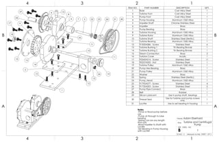
ITEM NO. PART NUMBER DESCRIPTION QTY.
1 Base Cast Alloy Steel 1
2 Turbine Foot Cast Alloy Steel 1
3 Pump Foot Cast Alloy Steel 1
4 Pump Housing Aluminum 1060 Alloy 1
5 Impeller Shaft Chrome Stainless Steel 1
6 Impeller Brass 1
7 Pump Bearing Brass 1
8 Turbine Housing Aluminum 1060 Alloy 1
9 Turbine Rotor Aluminum 1060 Alloy 1
10 Turbine Shaft Stainless Steel (ferritic) 1
11 Turbine Bearing Aluminum 1060 Alloy 1
12 91500A086 - Screw Stainless Steel 6
13 Turbine Bushing 1 Tin Bearing Bronze 1
14 Turbine Bushing 2 Tin Bearing Bronze 1
15 Steam Connection Brass 2
16 Turbine Cover Acrylic 1
17 95345A014 - Screw Stainless Steel 11
18 90257A005 - Nut Stainless Steel 1
19 Turbine Pulley Aluminum 1060 Alloy 1
20 Pump Hex Bearing Brass 1
21 Pump Pulley Aluminum 1060 Alloy 1
22 Washer Brass 1
23 Spring Stainless Steel (ferritic) 1
24 Pump_Head Aluminum 1060 Alloy 1
25 91792A077 - Screw Stainless Steel 4
26 91735A003 - Screw Stainless Steel 2
27 Pump Pipe Connect. Brass 1
28 Belt Rubber 1
29 Silicon Lubricant Use in pump shaft, bearings 1
30 Thread Seal Use for turbine and pump screws
only. 1
31 Loctite Use to set bearing in housing 1
4
A
123
B B
A
2 134
Turbine and Centrifugal
Pump
1
SHEET 1 OF 3SCALE: 1:1 Measure: Inches
DWG. NO.
B
SIZE
TITLE:
Name: Adam Eberhard
Notes
-Prime or flood pump before
use
-Pump oil through to lube
bearing
-Spring can be any length
that suits
-Bond Impeller to Shaft with
Loctite
-Set Bearing in Pump Housing
with Loctite
- 3. Name:
Adam Eberhard
.875
.750
.500
.094
.625
.188
3 .125
.313
.406
.125
1.375
21
.156
.063
.250
.375
.094
SECTION B-B
SCALE 3 : 2
#2-56
.219
R.438
.219
R.063
6
.125
.063
.094
SECTION C-C
SCALE 2 : 1
1.250
.875
.500
.250
.906
.625
#2-56, 5 equally
spaced Through
4
R.050
.141
#2-56
.344
.094
1.230
.531
.926
24 .063
.250
.375
.063
.188
SECTION D-D
SCALE 1.5 : 1
.125
.188
20
.375
.313
.125
5/16-24 Machine
Threads
.258
.031
.125
23
.266
.141
22
.016
.500
#8-36 Machine Threads
15
.188
.109
.250
.188
#8-36 Machine Threads
27
.164
.109
.188
.094
.063
.375
.281
.250
.219
.875
.125
.094
5.125
.375
.250
.125
7
.344
.172
.563
.281
SECTION R-R
SCALE 2 : 1
5 equally
spaced
Through
5 equally
spaced
Through
4
A
123
B B
A
2 134
SHEET 3 OF 3Centrifugal Pump