SlideShare a Scribd company logo
1 of 7
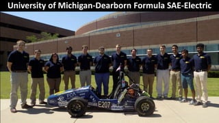
University of Michigan-Dearborn Formula SAE-Electric
Frame Design
• The 2016-2017 Frame was designed through
the use of SolidWorks
• A tubular space frame design was picked due
to its ease of manufacturability
• The newer design main focus is toward
greater accessibility to the drivetrain
packaging
FEA Testing
• An initial FEA tests was performed on
SolidWorks to get a general understanding
behind the frame’s torsional rigidity
• The rear suspension mounts were fixed, while a
150 lbf was applied to the front suspension
points
• The main goal of the FEA was to prove and
validate a frame stiffness which is about 8x the
roll-over stiffness
• Stiffness goal of 1500 lb-ft/deg was set, while a
1350 lb-ft/deg was achieved through FEA
Manufacturing Process
• A multi-plate jig system was used to position the frame
members for welding
• The method was used due to its ease of manufacturability
and lower overall cost compared to a modular jig system
• Plates were setup at certain (pre-set) positions for spot
welding
• After which the overall structure was TIG welded
Torsional Rigidity Test
• To further validate the new frame, a physical
torsional test was performed to compare the
FEA data to real life results
• The rear suspension points were fixed by
attaching the suspension points to a
stationary jig
• A bar was attached to the front suspension
rail, and a force of 150 lbf was applied on
either side in a torsional manner
• The deflection was measured by the use of
dial indicators which were setup at multiple
locations across the frame
• A torsional stiffness of 1389 lb-ft/deg was
measured which confirms our earlier FEA test
result of 1350 lb-ft/deg
Dynamic Testing
• Please use the attached link for video regarding Dynamic
testing
• https://www.youtube.com/watch?v=XxEFc2eMtWY
• Strain gauges and accelerometers are used to gather data
regarding frame and suspension
• Corrective measures and alterations are to be made
based on data gathered through testing
University of Michigan-Dearborn Formula SAE-Electric

More Related Content

What's hot

2015 UTSA Baja SAE Design Report
2015 UTSA Baja SAE Design Report2015 UTSA Baja SAE Design Report
2015 UTSA Baja SAE Design Report
Chase Jaffray
 
Statnamic testing of soils
Statnamic testing of soilsStatnamic testing of soils
Statnamic testing of soils
Sravan Muguda
 
Design and Analysis of a Tractor-Trailer Cabin Suspension
Design and Analysis of a Tractor-Trailer Cabin SuspensionDesign and Analysis of a Tractor-Trailer Cabin Suspension
Design and Analysis of a Tractor-Trailer Cabin Suspension
write2paras
 
DESIGN & STRUCTURAL PERFORMANCE ANALYSIS OF SUPRA SAE CAR CHASSIS
DESIGN & STRUCTURAL PERFORMANCE ANALYSIS OF SUPRA SAE CAR CHASSISDESIGN & STRUCTURAL PERFORMANCE ANALYSIS OF SUPRA SAE CAR CHASSIS
DESIGN & STRUCTURAL PERFORMANCE ANALYSIS OF SUPRA SAE CAR CHASSIS
Prashant Sahgal
 

What's hot (20)

Poster v3
Poster v3Poster v3
Poster v3
 
2015 UTSA Baja SAE Design Report
2015 UTSA Baja SAE Design Report2015 UTSA Baja SAE Design Report
2015 UTSA Baja SAE Design Report
 
Baja SAE USB 2010-2011 Portfolio
Baja SAE USB 2010-2011 PortfolioBaja SAE USB 2010-2011 Portfolio
Baja SAE USB 2010-2011 Portfolio
 
Formula SAE vehicle
Formula SAE vehicleFormula SAE vehicle
Formula SAE vehicle
 
Detailed design report on design of upright and hub
Detailed design report on design of upright and hubDetailed design report on design of upright and hub
Detailed design report on design of upright and hub
 
The osterberg cell static loading test
The osterberg cell static loading testThe osterberg cell static loading test
The osterberg cell static loading test
 
Design optimization of a roll cage of a sae baja car
Design optimization of a roll cage of a sae baja carDesign optimization of a roll cage of a sae baja car
Design optimization of a roll cage of a sae baja car
 
Grua titan de 26 ton international sterling 900 a
Grua titan de 26 ton international sterling 900 aGrua titan de 26 ton international sterling 900 a
Grua titan de 26 ton international sterling 900 a
 
Shear band test procedure
Shear band test procedureShear band test procedure
Shear band test procedure
 
Statnamic testing of soils
Statnamic testing of soilsStatnamic testing of soils
Statnamic testing of soils
 
Finite Element Analysis of a Rollercoaster Wheel Assembly - ME406 Final Project
Finite Element Analysis of a Rollercoaster Wheel Assembly - ME406 Final ProjectFinite Element Analysis of a Rollercoaster Wheel Assembly - ME406 Final Project
Finite Element Analysis of a Rollercoaster Wheel Assembly - ME406 Final Project
 
GEA31082 _SF_FS_R2
GEA31082 _SF_FS_R2GEA31082 _SF_FS_R2
GEA31082 _SF_FS_R2
 
Analysis of chassis
Analysis of chassisAnalysis of chassis
Analysis of chassis
 
IRJET - Research Review on Analysis of Load- Stress deflection Characteri...
IRJET -  	  Research Review on Analysis of Load- Stress deflection Characteri...IRJET -  	  Research Review on Analysis of Load- Stress deflection Characteri...
IRJET - Research Review on Analysis of Load- Stress deflection Characteri...
 
Workstation Bridge Cranes - O'Brien MET-TRACK
Workstation Bridge Cranes - O'Brien MET-TRACKWorkstation Bridge Cranes - O'Brien MET-TRACK
Workstation Bridge Cranes - O'Brien MET-TRACK
 
La te-x3
La te-x3La te-x3
La te-x3
 
Design and Analysis of a Tractor-Trailer Cabin Suspension
Design and Analysis of a Tractor-Trailer Cabin SuspensionDesign and Analysis of a Tractor-Trailer Cabin Suspension
Design and Analysis of a Tractor-Trailer Cabin Suspension
 
Cabin Ride Improvement of a Tector Trailer Vehicle
Cabin Ride Improvement of a Tector Trailer VehicleCabin Ride Improvement of a Tector Trailer Vehicle
Cabin Ride Improvement of a Tector Trailer Vehicle
 
DESIGN & STRUCTURAL PERFORMANCE ANALYSIS OF SUPRA SAE CAR CHASSIS
DESIGN & STRUCTURAL PERFORMANCE ANALYSIS OF SUPRA SAE CAR CHASSISDESIGN & STRUCTURAL PERFORMANCE ANALYSIS OF SUPRA SAE CAR CHASSIS
DESIGN & STRUCTURAL PERFORMANCE ANALYSIS OF SUPRA SAE CAR CHASSIS
 
Design and analysis of knuckle and hub of FSAE race car
Design and analysis of knuckle and hub of FSAE race carDesign and analysis of knuckle and hub of FSAE race car
Design and analysis of knuckle and hub of FSAE race car
 

Similar to University of Michigan-Dearborn Formula SAE Electric Frame Design

ENGR 402 Final Presentation.pptx
ENGR 402 Final Presentation.pptxENGR 402 Final Presentation.pptx
ENGR 402 Final Presentation.pptx
Will Davis
 
Final_TJ-SAMPE-Poster-Rev_CX
Final_TJ-SAMPE-Poster-Rev_CXFinal_TJ-SAMPE-Poster-Rev_CX
Final_TJ-SAMPE-Poster-Rev_CX
Xiao CHEN
 
Senior Project Presentation_Final
Senior Project Presentation_FinalSenior Project Presentation_Final
Senior Project Presentation_Final
Kate Mays
 
EME 185 Poster
EME 185 PosterEME 185 Poster
EME 185 Poster
tonygom
 

Similar to University of Michigan-Dearborn Formula SAE Electric Frame Design (20)

ENGR 402 Final Presentation.pptx
ENGR 402 Final Presentation.pptxENGR 402 Final Presentation.pptx
ENGR 402 Final Presentation.pptx
 
MSc VIVA
MSc VIVAMSc VIVA
MSc VIVA
 
Foundation notes
Foundation notesFoundation notes
Foundation notes
 
Final_TJ-SAMPE-Poster-Rev_CX
Final_TJ-SAMPE-Poster-Rev_CXFinal_TJ-SAMPE-Poster-Rev_CX
Final_TJ-SAMPE-Poster-Rev_CX
 
Senior Project Presentation_Final
Senior Project Presentation_FinalSenior Project Presentation_Final
Senior Project Presentation_Final
 
Experimental study of precast portal frame
Experimental study of precast portal frameExperimental study of precast portal frame
Experimental study of precast portal frame
 
Designing a Cold-Formed Steel Beam Using AS4600:2018 and 2005 - Webinar
Designing a Cold-Formed Steel Beam Using AS4600:2018 and 2005 - WebinarDesigning a Cold-Formed Steel Beam Using AS4600:2018 and 2005 - Webinar
Designing a Cold-Formed Steel Beam Using AS4600:2018 and 2005 - Webinar
 
TparsonsPoster
TparsonsPosterTparsonsPoster
TparsonsPoster
 
MTNS 1.pdf
MTNS 1.pdfMTNS 1.pdf
MTNS 1.pdf
 
Fabrication of composite leaf spring
Fabrication of composite  leaf springFabrication of composite  leaf spring
Fabrication of composite leaf spring
 
EME 185 Poster
EME 185 PosterEME 185 Poster
EME 185 Poster
 
Seimic Qualification of Transformers - Pradeep ProSIM
Seimic Qualification of Transformers - Pradeep ProSIMSeimic Qualification of Transformers - Pradeep ProSIM
Seimic Qualification of Transformers - Pradeep ProSIM
 
Team rhythmdesignathon
Team rhythmdesignathonTeam rhythmdesignathon
Team rhythmdesignathon
 
Shakerpresentation
ShakerpresentationShakerpresentation
Shakerpresentation
 
RINA - AOG 2017 - Development of Self Installing Deepwater Spar - ARUP - Ashi...
RINA - AOG 2017 - Development of Self Installing Deepwater Spar - ARUP - Ashi...RINA - AOG 2017 - Development of Self Installing Deepwater Spar - ARUP - Ashi...
RINA - AOG 2017 - Development of Self Installing Deepwater Spar - ARUP - Ashi...
 
Foundationnotes 121120064719-phpapp01
Foundationnotes 121120064719-phpapp01Foundationnotes 121120064719-phpapp01
Foundationnotes 121120064719-phpapp01
 
Standard Design Manual for FRP Composites Gratings
Standard Design Manual for FRP Composites GratingsStandard Design Manual for FRP Composites Gratings
Standard Design Manual for FRP Composites Gratings
 
Understanding the cause - Alan Burns and Gerard Chitty
Understanding the cause - Alan Burns and Gerard ChittyUnderstanding the cause - Alan Burns and Gerard Chitty
Understanding the cause - Alan Burns and Gerard Chitty
 
A Simplified Damage-following Model for Reinforced Concrete Columns
A Simplified Damage-following Model for Reinforced Concrete ColumnsA Simplified Damage-following Model for Reinforced Concrete Columns
A Simplified Damage-following Model for Reinforced Concrete Columns
 
My Work
My WorkMy Work
My Work
 

University of Michigan-Dearborn Formula SAE Electric Frame Design

  • 1. University of Michigan-Dearborn Formula SAE-Electric
  • 2. Frame Design • The 2016-2017 Frame was designed through the use of SolidWorks • A tubular space frame design was picked due to its ease of manufacturability • The newer design main focus is toward greater accessibility to the drivetrain packaging
  • 3. FEA Testing • An initial FEA tests was performed on SolidWorks to get a general understanding behind the frame’s torsional rigidity • The rear suspension mounts were fixed, while a 150 lbf was applied to the front suspension points • The main goal of the FEA was to prove and validate a frame stiffness which is about 8x the roll-over stiffness • Stiffness goal of 1500 lb-ft/deg was set, while a 1350 lb-ft/deg was achieved through FEA
  • 4. Manufacturing Process • A multi-plate jig system was used to position the frame members for welding • The method was used due to its ease of manufacturability and lower overall cost compared to a modular jig system • Plates were setup at certain (pre-set) positions for spot welding • After which the overall structure was TIG welded
  • 5. Torsional Rigidity Test • To further validate the new frame, a physical torsional test was performed to compare the FEA data to real life results • The rear suspension points were fixed by attaching the suspension points to a stationary jig • A bar was attached to the front suspension rail, and a force of 150 lbf was applied on either side in a torsional manner • The deflection was measured by the use of dial indicators which were setup at multiple locations across the frame • A torsional stiffness of 1389 lb-ft/deg was measured which confirms our earlier FEA test result of 1350 lb-ft/deg
  • 6. Dynamic Testing • Please use the attached link for video regarding Dynamic testing • https://www.youtube.com/watch?v=XxEFc2eMtWY • Strain gauges and accelerometers are used to gather data regarding frame and suspension • Corrective measures and alterations are to be made based on data gathered through testing
  • 7. University of Michigan-Dearborn Formula SAE-Electric