
Recommended
Recommended
More Related Content
Recently uploaded
Recently uploaded (20)
Featured
Featured (20)
Fischer nk10 float-switch-level-limiter-temperature-resistant
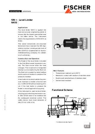
- 1. 28.2.08DB_GB_NK10.fm Applications The level limiter NK10 is applied into heat and process engineering plants to ensure that the lowest permissible level is not fallen below. The instrument meets the requirements of DIN 4574 as limiter. This series’ instruments are structural tested and have received the DIN regi- stration number / prototype test mark of DIN CERTCO Gesellschaft für Konfor- mitätsbewertung (company for validati- on of conformity). Construction and Operation The floater of the level limiter is located in the fluid filled vessel (expansion ves- sel). The float moves when the level changes. This movement is transported directly to a microswitch by the float rod. The float rod is sealed by metal bellows and its centre of rotation is outside of the pressure chamber. A test button is located outside the pres- sure chamber to enable a function test acc. to DIN 32728 without lowering of le- vel. If the test button is pressed the floater is moved against its buoyancy. If the instrument is used as level limiter, a locking and unlocking mechanism acc. to DIN 32728 need to be installed into the subsequent electrical control. This safety device must meet demands of DIN 57116 / VDE 0116. Functional Scheme Main Features • Temperature resistant up to 400°C • Material in contact with medium of stainless steel • Double wall metal bellows of stainless steel • Varnish heat resistant * in reference to density 1kg/dm³ Welded socket Float rod Metal bellows Test button M16x1.5 connection Counter flange Lever Microswitch S1 Float 10N NK10 Level Limiter
- 2. Specifications Electrical Connection Variants 10N80, 10N65, 10NS80, 10NS90 Max. operating pressure 16 bar Max. medium temperature 400°C Perm. ambient temperature 70°C Variant 10N65/10 Max. operating pressure 10 bar Max. medium temperature 350°C Perm. ambient temperature 70°C For all variants Max. load data 250 V, 6 A ohmic resistance Electrical connection internal connector bloc Protection class IP55 acc. to DIN EN 60529 Specified minimum density rho = 0.6 kg/dm³ Switching hysteresis approx. 6 mm Mounting position horizontal For all variants with 2 micro switches Switching point difference max. 30 mm at surface of medium depends on density of medium Materials Float system stainless steel 1.4301 Metal bellows stainless steel 1.4541 Welded socket St. 35.8 Flange 1.0425 (H II) resp. 15 Mo 3 1 Microswitch 2 Microswitches Test button Test button
- 3. Dimensions (all units in mm unless otherwise stated) Mounting Variant 10N80 NK102 The instrument is desinged with a mounting flange acc. to DIN flanges - DN 80 PN 25. The float must be able to move freely in vertical direction! Mounting Variants 10N65 NK101 10N65/10 NK103 The instrument is desinged with mounting flange with con- nection dimensions acc. to DIN 2501. Connection dimensions 10N65 - DN 65 PN 25 10N65/10 - DN 65 PN 16 The float must be able to move freely in vertical direction! Mounting Variants 10NS80 NK104 10NS90 NK105 The welded socket is welded into the expansion vessel acc. to DIN 4754. Regard the moun- ting position. The float must be able to move freely in vertical direction! Variants Var.: Size A Size B Size C Size D 10NS80 220 365 82.5 77.5x77.5 10NS90 250 395 88.9 90x90 Variant PN25 8 x Ø18 PN16 4 x Ø18 18 resp. 22
- 4. Technische Änderungen vorbehalten • Subject to change without notice • Changements techniques sous réserve Fischer Mess- und Regeltechnik GmbH • Bielefelder Str. 37a • D-32107 Bad Salzuflen • Tel. +49 5222 9740 • Fax +49 5222 7170 • eMail: info@fischermesstechnik.de • www.fischermesstechnik.de Ordering Code Level Limiter 10N Type Series Flange connection acc. to DIN 2527 form E DN65 PN25 . > 65 ..................> 1 Flange connection acc. to DIN 2527 form E DN80 PN25 . > 80 ..................> 2 Flange connection acc. to DIN 2527 form E DN65 PN16 . > 65/10 ..................> 3 Welding connection - 82.5 mm............................................ > S80 ..................> 4 Welding connection - 88.9 mm............................................ > S90 ..................> 5 Switching Section 1 Microswitch .............................................................................. > K1 .......................................................> 1 2 Microswitch .............................................................................. > K2 .......................................................> 2 00 0000NK10