1. www.elsevier.com/locate/jmbbm
Available online at www.sciencedirect.com
Research Paper
Monotonic and cyclic loading behavior of porous
scaffolds made from poly(para-phenylene)
for orthopedic applications
Anthony J. Hoyta
, Christopher M. Yakackib
, Ray S. Fertig IIIa
,
R. Dana Carpenterb
, Carl P. Fricka,n
a
University of Wyoming, Department of Mechanical Engineering, Laramie, WY, USA
b
University of Colorado Denver, Department of Mechanical Engineering, Denver, CO, USA
a r t i c l e i n f o
Article history:
Received 20 June 2014
Received in revised form
2 October 2014
Accepted 6 October 2014
Available online 16 October 2014
Keywords:
Aromatic polymers
Porous
Fatigue
Orthopedics
Poly(para-phenylene)
Mechanical properties
a b s t r a c t
Porous poly(para-phenylene) (PPP) scaffolds have tremendous potential as an orthopedic
biomaterial; however, the underlying mechanisms controlling the monotonic and cyclic
behavior are poorly understood. The purpose of this study was to develop a method to
integrate micro-computed tomography (μCT), finite-element analysis (FEA), and experi-
mental results to uncover the relationships between the porous structure and mechanical
behavior. The μCT images were taken from porous PPP scaffolds with a porosity of 75 vol%
and pore size distribution between 420 and 500 mm. Representative sections of the image
were segmented and converted into finite-element meshes. It was shown through FEA that
localized stresses within the microstructure were approximately 100 times higher than the
applied global stress during the linear loading regime. Experimental analysis revealed the
S–N fatigue curves for fully dense and porous PPP samples were parallel on log–log plots,
with the endurance limit for porous samples in tension being approximately 100 times
lower than their solid PPP counterparts (0.3–35 MPa) due to the extreme stress concentra-
tions caused by the porous microarchitecture. The endurance limit for porous samples in
compression was much higher than in tension (1.60 MPa). Through optical, laser-scanning,
and scanning-electron microscopy it was found that porous tensile samples failed under
Mode I fracture in both monotonic and cyclic loading. By comparison, porous compressive
samples failed via strut buckling/pore collapse monotonically and by shearing fracture
during cyclic loading. Monotonic loading showed that deformation behavior was strongly
correlated with pore volume fraction, matching foam theory well; however, fatigue
behavior was much more sensitive to local stresses believed to cause crack nucleation.
& 2014 Elsevier Ltd. All rights reserved.
http://dx.doi.org/10.1016/j.jmbbm.2014.10.004
1751-6161/& 2014 Elsevier Ltd. All rights reserved.
n
Corresponding author. Tel.: þ1 303 766 4068.
E-mail address: cfrick@uwyo.edu (C.P. Frick).
j o u r n a l o f t h e m e c h a n i c a l b e h a v i o r o f b i o m e d i c a l m a t e r i a l s 4 1 ( 2 0 1 5 ) 1 3 6 – 1 4 8
2. 1. Introduction
Poly(para-phenylenes) (PPPs) consist of directly linked repeat-
ing phenyl units (benzene rings) resulting in strength and
stiffness values much greater than other traditional polymeric
biomaterials (Morgan et al., 2006; Pei and Friedrich, 2012;
Vuorinen et al., 2008). A recent approach in the polymerization
of PPPs has been to add side groups to the aromatic backbone,
which allows for increased degree of polymerization (Taylor
and Samulski, 2000; Percec et al., 1999; Cianga et al., 2002).
Therefore, PPPs can now be manufactured in bulk, which has
allowed them to be used as a structural engineering material
with excellent chemical stability. They are widely considered
the stiffest and strongest commercially available thermoplas-
tics, even though their material properties can vary based on
the specific side groups present.
To date only a handful of studies have investigated the
potential use of PPPs as a biomaterial. A study by Vuorinen
et al. (2008) investigated the effect of water absorption on the
mechanical properties of PPP. They showed that water absorp-
tion was less than 1% after 44 days of soaking and a little-to-no
effect was observed on the mechanical properties. Further
testing by some of the current authors revealed that the
mechanical properties stayed within one standard deviation
of dry conditions after soaking in an aqueous environment for
over 1 year (Frick et al., 2014). The bulky side groups within the
structure of PPPs act as diffusional barriers that prevent water
molecules from swelling the polymer (Barnes et al., 1988;
Corkhill et al., 1987), resulting in negligible effects on the
mechanical properties. In addition to absorption testing, initial
cytotoxicity testing of PPP (Frick et al., 2014) shows that it is
non-toxic, which was expected due to its chemical inertness.
The mechanical characteristics of the PPP used in this study
(PrimoSpire PR-250) were determined in comparison to other
common biomedical grade polymers (Frick et al., 2014); it was
found that PPP has strength and stiffness much greater than
these materials. It was shown that PPP has an average tensile
strength of 141 MPa, exceeding that of polyetheretherketone
(PEEK) (96 MPa) and high density polyethelene (HDPE) (30 MPa).
It was also shown that the average elastic modulus of PPP is
approximately 5.0 GPa, far greater than that of PEEK, which
ranges from 2.2 to 3.4 GPa (Yakacki, 2013), and HDPE, which is
approximately 1.10 GPa (Callister and Rethwisch, 2010). The
direct linkage of repeating phenyl units inherent in the micro-
structure of PPP provides strong anti-rotational biaryl bonds
which lead to its exceptional mechanical strength and stiffness.
Moreover, the addition of side groups along its backbone causes
steric hindrance which further limit chain mobility. Despite its
outstanding mechanical behavior, the viability of PPP as a load-
bearing biomaterial has been largely uninvestigated.
Porous scaffolds are commonly proposed for orthopedic
applications to overcome the failures associated with the loosen-
ing of the implant–bone interface (Agrawal and Ray, 2001;
Hench, 1991; Rezwan et al., 2006; Converse et al., 2010, 2009;
Karageorgiou and Kaplan, 2005; Causa et al., 2006; Kretlow and
Mikos, 2007). A porous scaffold could alleviate these problems by
allowing for osteointegration, i.e. the physical intermix of bone
and implant. The fundamental premise is that during heal-
ing the osteoblast cells will penetrate and proliferate into the
open-cell porous scaffold. A critical challenge facing orthopedic
implants is matching the mechanical properties of trabecular
bone. Metal implants tend to have far greater mechanical
properties than bone, leading to stress shielding which prevents
full healing of the injured site (Bobyn et al., 1992; Bugbee et al.,
1997; Nagels et al., 2003; Lewis, 2013). Along with this, bone
resorption is common due to the disuse and lack of stimulus for
bone maintenance. Porous scaffolds made from traditional
polymeric biomaterials lack the strength and stiffness required
to match those of trabecular bone. But due to the high bulk
modulus of PPP, it can be manufactured at a relatively high
porosity, which is necessary for successful osteointegration
in vivo (Karageorgiou and Kaplan, 2005), while still matching
the mechanical properties of trabecular bone. For example, a
recent study found that the elastic modulus of 80 vol% porous
PPP was over 120 MPa, while for 70 vol% porous PPP it was
approximately 300 MPa (DiRienzo et al., 2014).
The manner in which PPP scaffolds can be manufactured
also makes it a viable candidate for orthopedic applications.
PPP can be solution cast, hot injection molded, or hot-press
sintered into a desired geometry. A manufacturing technique
for fabricating porous PPP was established in a previous study
(DiRienzo et al., 2014). It was shown that for a large array of
porosities and pore sizes, monotonic properties roughly
matched those predicted by foam theory (Gibson and
Ashby, 1988). Although a range of porous samples have
already been monotonically tested, the fatigue characteriza-
tion of the porous scaffolds was not conducted. Other studies
have investigated the mechanical properties of biomedical
porous structures and have taken into account the fatigue
characteristics (Lewis, 2013; Banhart, 2001; Landy et al., 2013;
Lipinski et al., 2013; Yavari et al., 2013). For example, Banhart
listed fatigue testing of porous scaffolds as a necessary
destructive test in the characterization of potential biomedi-
cal materials. Furthermore, the study by Landy et al. empha-
sized that porous PEEK met the fatigue criteria necessary for
its development as a cervical interbody fusion cage. Under-
standing the fatigue resistance of potential biomaterials for
orthopedic applications is of utmost importance due to the
cyclic nature of physiological loading (Pruitt, 2005).
While the fatigue behavior of fully dense PPP has been
investigated in a previous study (Frick et al., 2014), the fatigue
behavior of porous PPP is completely unexplored. Cyclic load-
ing is a common source of failure in polymeric orthopedic
devices due to the nature of human motion (Simske et al., 1997;
Ganguly et al., 2004; Hartwig and Knaak, 1991; Brillhart and
Botsis, 1994; Brillhart et al., 1991; Sobieraj et al., 2010), as such,
it has been well documented that this effect must be taken into
account when developing a new polymer based biomaterial.
The purpose of this study is to further investigate the porous
PPP that most closely matches trabecular bone: 75 vol% porous
scaffolds with large pore size distribution between 420 and
500 mm (DiRienzo et al., 2014). The large pore size generally
agrees with the principles of osteointegration in which pores
that are greater than 300 mm are recommended (Karageorgiou
and Kaplan, 2005).
The focus of this study was to develop a method that utilizes
a combination of micro-computed tomography (mCT) analysis,
finite-element analysis (FEA), and experimental testing to
understand both monotonic and cyclic behavior as well as
j o u r n a l o f t h e m e c h a n i c a l b e h a v i o r o f b i o m e d i c a l m a t e r i a l s 4 1 ( 2 0 1 5 ) 1 3 6 – 1 4 8 137
3. how the local stresses affect the overall porous behavior. The
mCT results were used to quantitatively characterize the porous
structure, and were subsequently used as input into the finite-
element model. The inherent advantage of this technique is
that it is possible to quantitatively develop a 3D model of a
complex microstructure. FEA was then used to identify stresses
in discrete spatial locations throughout the porous microstruc-
ture induced by global loading. By comparing experimental
results to the finite-element model, an understanding of the
underlying mechanisms for fatigue and monotonic failure was
established. The technique used in this work is similar to that
used in other porous scaffold research (Elliott et al., 2002;
Youssef et al., 2005; Kashef et al., 2013); however, these studies
did not explicitly link the FEA to the cyclic behavior. The
method of analysis presented here represents a potential
technique for understanding and predicting monotonic and
fatigue behavior for any novel micron-scale structure, and to
effectively relate the structure to the mechanical properties.
2. Experimental methods
2.1. Materials
The PPP used in this study was PrimoSpire PR-250, provided in
powder form by Solvay Specialty Polymers, Inc. (Alpharetta,
GA). Previous work has shown that PrimoSpire PR-250 consists
of an aromatic backbone with aromatic side groups (Frick
et al., 2014). Sodium chloride (NaCl) was purchased from
Sigma-Aldrich Co. LLC (St. Louis, MO) and was separated by
a sifting process to attain the desired crystal size appropriate
for this study (420–500 mm).
2.2. Compression molding
Open-cell porous PPP scaffolds were fabricated by a sintering
technique developed from past research (DiRienzo et al., 2014).
Briefly, this technique involved thoroughly mixing appropriate
ratios of NaCl to PPP powder for a desired porosity based on final
volume and the density of each constituent. Once the PPP powder
and NaCl were mixed for the desired porosity of 75 vol%, samples
were hot-press powder sintered using a hydraulic high-tem-
perature press (Model DV-62-422, Pasadena Hydraulics, Inc.).
Tensile samples were made from pressed plaques, from which
the samples were cut to dogbone shapes of dimensions recom-
mended in ASTM standard D638. Cylindrical compression sam-
ples of dimensions approximately 8Â 15 mm2
were fabricated in
custom made cylindrical aluminum molds. Both tensile and
compressive porous samples were then submerged in distilled
water and agitated on a shaker plate heated to 90 1C at 60 rpm for
7–10 days, changing water daily, to ensure that all of the NaCl
was leached. Samples were then dried in a vacuum oven at 90 1C
for 24 h. Density measurements were then performed to validate
that the desired porosity was reached. In all cases the actual
porosity was within 1.5 vol% of the desired value.
2.3. lCT imaging
Images of a representative cylindrical sample were obtained
using a μCT system (Inveon micro PET/CT, Siemens Medical
Solutions USA, Inc., Malvern, PA) with an isometric voxel size
of 31 μm. The images were imported into ScanIP (Simpleware,
Ltd., Exeter, UK) software for image processing and finite-
element mesh generation. Voxels containing PPP were seg-
mented from the surrounding air using a threshold-driven
region growing algorithm. The lower threshold was adjusted
so that the porosity of the model matched the known porosity
of 75 vol%. In order to accurately represent the overall beha-
vior of the porous structure, the sample size must be at least
five times the mean pore size (Roberts and Garboczi, 2002).
Accordingly, a 3-mm cube of the material (also with 75 vol%
porosity) was then selected from the center of the cylindrical
sample. An island removal filter was used to remove any
fragments that were unconnected to the material structure,
and a cavity fill process was used to remove any small voids in
the material. The voxels in the image were then converted to
tetrahedral elements for subsequent finite-element analysis.
2.4. Monotonic testing
Uniaxial monotonic tensile and compression testing was
conducted on a hydraulic load frame (858 Mini Bionix II, MTS
Systems Corporation, Eden Prairie, MN) equipped with a laser
extensometer (LX 500, MTS Systems Corporation, Eden Prairie,
MN) at a displacement rate of 0.01 mm/s. Reflective tape was
placed directly on the sample for tensile testing and on the
load frame platens for compression tests. Tensile samples
were strained until fracture and compression tests were
strained well into the third regime of compression behavior
(densification). Tensile yield was defined as the maximum
stress on the stress–strain plot. Compression yield was defined
as the stress associated with the intersection of a linear fit to
the elastic region and a linear fit to the plateau region.
2.5. FEA
To study the local stresses induced within the 75 vol% porous
PPP scaffold, a finite-element mesh composed of 1.2 million
3D tetrahedral elements was constructed from the mCT
images using the ScanIP software described previously. This
mesh was imported into Abaqus (SIMULIA, 2011) for analysis
and a C3D10 (fully integrated quadratic tetragonal element)
was selected. A cube of material 3 mm on each edge was
selected for analysis. Because this section represented an
internal section of the tested material, boundary conditions
were imposed on the cube surface to ensure that surface
planes remained planar and did not rotate out of their initial
planes. Normal displacements on all negative cube faces
were constrained to be zero. Reference points were created
on each of the positive cube surfaces and equation con-
straints were used to tie normal degrees of freedom for all
positive cube faces to corresponding degrees of freedom on
the corresponding surface reference point. Displacement
controlled loading was prescribed on the top surface refer-
ence node such that the global strain was ramped up to 10%.
The material was assumed to behave as an isotropic elasto-
plastic material with initial elastic modulus of 4.9 GPa and a
Poisson ratio of 0.38; this corresponded with the average bulk
j o u r n a l o f t h e m e c h a n i c a l b e h a v i o r o f b i o m e d i c a l m a t e r i a l s 4 1 ( 2 0 1 5 ) 1 3 6 – 1 4 8138
4. behavior measured for PPP. An isotropic plasticity model was
used in which yielding occurred at 204 MPa with linear
hardening to a plastic strain of 200% at 215 MPa (nearly
perectly plastic).
2.6. Fatigue testing
Tensile and compressive samples were fatigued using a Bose
ElectroForce 3200 DMA (Eden Prairie, MN) at frequencies of
1 Hz and 10 Hz under load control. It was shown through
previous research that frequency had no effect on the fatigue
behavior of fully dense PPP resulting in the scatter of data
falling in line with one another (Frick et al., 2014). Due to the
high glass transition temperature of PPP ($177 1C) there is
little concern of localized heating that would diminish the
fatigue properties. Samples pertinent to this report were
subjected to cyclic loading (RE0) until failure and the number
of cycles for each stress was recorded to populate an S–N
curve (i.e. stress vs. number of cycles-to-failure). The number
of cycles-to-failure for tensile samples was defined at frac-
ture. For these samples, the Bose system took approximately
100–300 cycles to reach the maximum cyclic stress; samples
that retained this stress for at least two decades of log cycles
were kept for analysis. The cycles-to-failure for compression
was defined as a sudden increase in accumulated strain as
evident from a plot of strain vs. number of cycles. Some plots
showed a gradual accumulation in strain as cycles increased;
for these, a strain of 5% was defined as failure, which
correlates with the yield strain from the monotonically tested
compression results. The results from the fatigue analysis in
both compression and tension were assembled into an S–N
curve to show the general fatigue behavior of the material.
The endurance limit (i.e. fatigue strength) for both tension
and compression was defined as the stress associated with
the survival of 106
cycles. In total, 15 samples were tested in
tension, and 14 samples were tested in compression.
2.7. Dynamic mechanical analysis (DMA)
The modulus of 75 vol% porous PPP was determined using thin
strips with approximate dimensions of 1.25 Â 4.5Â 35 mm3
.
Tension and compression modulus testing was performed on
a DMA (TA Instruments DMA Q800, Newcastle, DE) at approxi-
mately room temperature (25 1C). Samples were preloaded with
a force associated with a stress well within the linear elastic
region and then cyclically strained from 0% to 0.10% in either
compression (n¼4) or tension (n¼3).
2.8. Imaging
Optical images were taken of representative porous tensile
and compressive samples to analyze the fracture surface using
an Imaging Source camera (model DBK31BU03.H, Bremen,
Germany) equipped with a Navitar Zoom 7000 lens (Rochester,
New York). Images were uploaded into IC Capture Version 2.2
imaging acquisition software, also by Imaging Source.
Laser-scanning microscopy (LSM) images were taken using
an Olympus LEXT OLS4100 laser scanning microscope (Center
Valley, PA) at an optical zoom of 5 Â . Because the field of view
was approximately 5 mm2
at this magnification, a stitch
function within the LEXT software was utilized to build
images of the entire fracture surface for tensile and com-
pressive samples.
High magnification images were taken using an FEI Quanta
450 (Hillsboro, OR) field emission scanning-electron microscope
(SEM). Images were taken using the secondary electron detector
at a voltage of 5 kV and a working distance of approximately
10 mm. Samples were coated in carbon before imaging.
3. Results
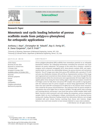
The mCT image of a representative 75 vol% porous PPP scaf-
fold is shown in Fig. 1. Analysis of the image verified that all
Fig. 1 – μCT image of 75 vol% porous PPP compressive scaffold with an enlarged cutout view. This image shows that all NaCl
had been fully leached from the structure. Also illustrated are the irregular strut patterns, peculiar cell shapes, and local
fluctuations of relative density. The cutout is the RVE used as the input into the FEA model.
j o u r n a l o f t h e m e c h a n i c a l b e h a v i o r o f b i o m e d i c a l m a t e r i a l s 4 1 ( 2 0 1 5 ) 1 3 6 – 1 4 8 139
5. the NaCl particles had been successfully leached, leaving
behind an open-cell porous structure. In addition, the μCT
image illustrates the irregular strut patterns, peculiar cell
shapes, and local fluctuations of relative density. It is appar-
ent that the actual structure of the porous scaffold differs
drastically from the simple geometry defined by foam theory
(Gibson and Ashby, 1988). The results from this analysis were
subsequently used as the input for the FEA model; a 3 mm by
3 mm cube of material within the scaffold was selected such
that the internal behavior of the structure could be modeled
without the external effects associated with a free edge.
The monotonic strain-to-failure plots of 75 vol% porous PPP
shown in Fig. 2A and B illustrate the general behavior of porous
PPP in tension and compression, respectively. In tension, the
porous scaffold shows a linear region followed by a short
plateau and fracture. Failure is brittle in nature with an average
elastic modulus of 143 MPa followed by an average strength of
3.5 MPa. The compression testing of porous PPP shows the
three regimes typical of porous elastomeric compressive beha-
vior similar to that described by Gibson and Ashby (1988),
whose model consisted of interconnected beams. During load-
ing there was first an elastic portion where stress increases
linearly with deformation; in this regime the struts of the
porous scaffold elastically bend. Upon subsequent loading
there is a deviation from linearity in which the stress app-
roaches a plateau regime; here individual struts bend and
buckle at discrete locations. Finally, a densification regime in
which the struts plastically deform and collapse, ultimately
crushing the porous structure. In this regime, the stress rises
steeply and the porous structure begins to behave as a
compacted solid. The average elastic modulus and strength
in compression of the porous scaffold were 167 MPa and
6.6 MPa, respectively. Table 1 summarizes averaged porous
mechanical properties and one standard deviation alongside
Fig. 2 – Monotonic strain-to-failure behavior of
representative 75 vol% porous PPP. (A) Tensile results show
brittle behavior and premature failure. (B) Compressive
results show the 3 stages typical of porous compressive
behavior: linear elastic, plateau, and densification.
Table 1 – Mechanical properties of 75 vol% porous PPP in
comparison to fully dense PPP. The listed values repre-
sent the average and one standard deviation.
Fully dense PPP (MPa)
Elastic modulus 50087562
Tensile strength 141.1710.0
Compressive strength 167.877.1
Porous PPP (MPa)
Tensile modulus 142.9713.9
Tensile strength 3.570.2
Compressive modulus 167.4718.5
Compressive strength 6.670.3
Fig. 3 – (A) Maximum principal stresses (in MPa) shown for a
75 vol% RVE under an applied tensile stress of 0.14 MPa. All
deformation under this applied load is elastic. (B) Tensile
results from FEA model compared with representative
experimental data.
j o u r n a l o f t h e m e c h a n i c a l b e h a v i o r o f b i o m e d i c a l m a t e r i a l s 4 1 ( 2 0 1 5 ) 1 3 6 – 1 4 8140
6. the yield strength and modulus of fully dense PPP in both
tension and compression.
Fig. 3A shows the local maximum principal stresses in the
porous scaffold computed using the FEA under purely elastic
loading of a globally applied stress of 0.14 MPa. Note that
localized strut regions in the porous material are under stresses
two orders of magnitude larger than the applied stress. A
predicted FEA tensile stress–strain curve was computed and
compared with the experimental results of Fig. 2A. This
comparison is shown in Fig. 3B, where good agreement is
observed up to failure of the experimental sample. The dis-
crepancy immediately prior to failure is due to the fact that
fracture is not explicitly modeled in the FEA simulation,
whereas fracture is the final failure associated with the experi-
mental data. Nevertheless, the local stresses in the elastic
loading regime prior to failure are assumed to be accurate.
Fatigue testing was conducted on 75 vol% porous PPP in
tension and compression, and compared to tensile fatigue of
fully dense PPP (Frick et al., 2014). Fig. 4A shows the number
of cycles to failure as a function of applied stress (so-called
S–N curves). Fig. 4B displays just the porous samples in semi-log
plot format for clarity. As can be seen, the general characteristic
of both curves follows a typical power law curve fit of the form
originally proposed by Basquin (1910)
σ ¼ ANb
f ð1Þ
where Nf is the number of cycles to failure associated with an
induced cyclic stress amplitude, σ, while A and b are constants
that are determined through a least squares approach used to
fit a line to the data points. From these relationships, the
constants from Eq. (1) were determined for each fatigue test
and are presented in Table 2. It is important to note that the
values for b are relatively close for all three fatigue tests,
indicating that the general behavior is similar. In fact, they all
show values close to À0.2, resulting in three nearly parallel
curves, as is evident in Fig. 4A.
For this study the endurance limit was defined as the stress
associated with a sample that did not fail while surpassing 106
cycles. Table 2 also summarizes the experimental endurance
limits achieved during this study, which are also shown on the
S–N curves in Fig. 4 denoted as σe. As suggested by the large
differences in strengths between compression and tension in the
monotonic tests, the porous scaffold had a significantly higher
endurance limit (approximately a factor of 5) in compression
than in tension. There is also a noticeably large difference
between the endurance limit of fully dense and porous PPP
samples. In fact, the ratio of fully dense tensile to porous tensile
endurance limits is nearly a factor of 117. A large difference is
expected since the introduction of voids into the bulk structure
also introduces a large amount of stress concentration as well as
a significant reduction in cross-sectional area.
To further explore the behavior of 75 vol% porous PPP in
fatigue, data was extrapolated on a per cycle basis. The results
of this are shown in Figs. 5 and 6 for tension and compres-
sion, respectively. Fig. 5A displays the stress–strain relationship
for selected cycles throughout the lifetime of a representative
porous tensile sample. The behavior remained linear-elastic
throughout the lifetime of the sample with little-to-no evidence
of a hysteresis. With increasing number of cycles, the slope of
the curve begins to decrease. Fig. 5B shows the modulus and
accumulation of strain as a function of cycles for the same
porous tensile sample. The modulus remained relatively con-
stant up until a critical point at around half its fatigue lifetime.
This effect is somewhat mirrored by the constant strain
associated with each cycle shown on the same plot up to the
onset of fracture where strain increased rapidly to failure.
Furthermore, there is a small change in the rate of strain
Fig. 4 – (A) An S–N curve comparing fully dense PPP to 75 vol%
porous PPP in tension and compression. This shows the
tensile fatigue strength (σe) of fully dense PPP and also the
near parallel relationship between fully dense, porous
compression, and porous tension. Note: Log–log scale.
(B) Zoomed in view of S–N curve to include just 75 vol%
porous PPP samples on a semi-log plot for clarity. This shows
the porous fatigue strength for both compressive and tensile
samples (σe).
Table 2 – Constants A and b associated with Eq. (1),
determined through power law curve fit to experimental
results, for fully dense PPP and 75 vol% porous PPP in
both compression and tension. Note the similarity in
values for the exponential (b). Also listed are the endur-
ance limits reached for fully dense and both porous
samples. The porous compressive samples had a higher
endurance limit than the porous tensile samples.
PPP sample A b Endurance limit
(MPa)
Fully dense 329.0 À0.18 35
Porous—
compression
39.4 À0.23 1.60
Porous—tension 6.4 À0.21 0.30
j o u r n a l o f t h e m e c h a n i c a l b e h a v i o r o f b i o m e d i c a l m a t e r i a l s 4 1 ( 2 0 1 5 ) 1 3 6 – 1 4 8 141
7. accumulation at approximately the same point where the
modulus is seen to diminish, suggesting a deviation from
linear-elastic behavior. Similar results are seen for a represen-
tative porous sample in compression, as presented in Fig. 6. The
stress–strain relationship illustrated in Fig. 6A shows that most
of the lifetime of the compression sample remained elastic with
no evidence of a hysteresis. Upon further cyclic loading there is
a noticeable shift in the curve denoting plastic deformation
within the region associated with fracture. Fig. 6B shows that
the modulus remained constant throughout the lifetime of the
sample up until the onset of fracture where the modulus
decreased rapidly. This effect is a reflection of the accumulation
of strain shown on the same plot for the porous compression
sample. Strain remained constant throughout the lifetime of
the sample with a drastic increase with the onset of fracture,
which was also captured in the stress–strain plot in Fig. 6A.
Fig. 7A illustrates a tensile fatigue fracture surface of a
representative porous sample through optical, LSM, and SEM
imaging alongside Fig. 7B which shows analogous results for a
monotonic tensile fracture surface. As is evident from the
optical image in column A, the porous tensile fatigue sample
fractured nearly perpendicular to the direction of loading,
indicating brittle Mode I fracture, similar to that of the mono-
tonically tested sample in column B. The LSM images show the
height contours of the fatigue fracture surfaces. The color scale
included with each image illustrates the height associated with
each color; red being the highest and purple/black being the
lowest. Thus, the red on the tensile samples indicate a smooth
surface and the yellow/green openings throughout the sample
indicate the presence of pores. If there were cracks formed
away from the fracture surface they would be visible by yellow
or green cracks throughout the red surface. The LSM images
also show surface artifacts formed by imperfections in the
aluminum molding plates. This was verified through LSM
imaging of an untested sample, which showed these same
surface artifacts. Further investigation near the fracture surface
with the SEM for both the fatigue and monotonically loaded
specimens showed no evidence of global damage away from
the fracture surface. These collections of images indicate that
nucleation and propagation of a single crack lead to ultimate
failure of the sample.
Fig. 6 – (A) Stress–strain relationship for selected fatigue
cycles throughout the lifetime of a representative 75 vol%
porous PPP compressive sample (failed at 18,320 cycles). The
curves remain nearly in line with one another with no
hysteresis up until the onset of fracture where plastic strain
is seen to occur. (B) Modulus and strain accumulation as a
function of log cycles for the same compressive sample.
Modulus remains constant throughout the majority of the
sample lifetime, with a sudden decrease in modulus at the
onset of fracture. The accumulated strain remains constant
as well, with a sharp increase at the onset of fracture. Failure
is brought on by shearing mechanisms.
Fig. 5 – (A) Stress–strain relationship for selected fatigue
cycles throughout the lifetime of a representative 75 vol%
porous PPP tensile sample (failure at 83,448 cycles). The
curves remain nearly parallel to one another for most of the
fatigue life, with little-to-no hysteresis and a small decrease
in modulus as the onset of fracture approached. (B) Modulus
and strain accumulation as a function of log cycles for the
same tensile sample. Modulus remains constant throughout
most of the sample lifetime, with a gradual decrease in
modulus towards the onset of fracture. The strain remains
constant as well, with a gradual change in strain rate before
a sharp change at the onset of fracture. Failure occurs
through brittle Mode I fracture.
j o u r n a l o f t h e m e c h a n i c a l b e h a v i o r o f b i o m e d i c a l m a t e r i a l s 4 1 ( 2 0 1 5 ) 1 3 6 – 1 4 8142
8. The image collections in Fig. 8 show the fracture surface of a
representative fatigued compressive sample (Fig. 8A) alongside
a monotonically failed sample (Fig. 8B), in the same manner as
that of Fig. 7. These images clearly show the differences in
failure of the fatigue sample and the monotonic sample. The
fatigue failure illustrates a crack which formed in the direction
of maximum shear stress, while the monotonic sample experi-
enced pore collapse and ultimate densification. The fatigue
fracture surface in column A showed no evidence of cracks
forming away from the failure crack, indicating strut failure in
a localized area and crack propagation in the direction of
maximum shear stress. However, it is important to note that
heavy material damage occurred in the shear band area around
the crack. The monotonically failed sample shows that pores
collapsed which escalated into densification throughout the
structure.
Supplemental videos showing the failure of representative
samples of porous fatigue fracture in tension and compression
are available for viewing online. Reflective of the behavior
shown in Figs. 5 and 7; the tensile sample showed brittle Mode
I fracture. The supplemental video showing fatigue failure
of a representative compression sample is reflective of the
behavior shown in Figs. 6 and 8. This video shows the
propagation of a shear crack in the direction of maximum
shear stress. At this point particles begin to fall from the crack
as the two surfaces of the nucleated crack rub against one
another. Ultimately, this is of no concern since failure was
eminent at this point. At low cycles there were no particles
expelled from the structure since the shear crack had not
formed and the behavior remained elastic. The final stage of
failure is shown at the end of the video, which reveals a shear
crack similar to that shown in Fig. 8A.
4. Discussion
The purpose of this study was to characterize the monotonic
and fatigue behavior of 75 vol% porous PPP and to investigate
the associated failure mechanisms. As porous PPP has been
suggested as an orthopedic biomaterial, a basic characterization
of its material properties is an important first step. It is
important to understand the fatigue characteristics of potential
Fig. 7 – Tensile samples of 75 vol% porous PPP showing fracture surface through optical, LSM, and SEM imaging techniques.
Successive images shown in columns A and B are of a tensile fatigue sample and a monotonically tested tensile sample,
respectively. As is evident from the images, there are no signs of cracking away from the fracture surface for both fatigued and
monotonically failed samples. Both exhibit Mode I fracture in which a strut fails and the crack coelesced until ultimate failure
of the sample.
j o u r n a l o f t h e m e c h a n i c a l b e h a v i o r o f b i o m e d i c a l m a t e r i a l s 4 1 ( 2 0 1 5 ) 1 3 6 – 1 4 8 143
9. biomaterials due to the cyclic nature of loading in the human
body as a result of daily activity. For example, soft-tissue
fixation procedures generally require 8–12 weeks for healing
to take place (Rodeo et al., 1993) and need to be fully supported
by the implanted device for the duration of this process. In
addition, the implant must have mechanical properties similar
to trabecular bone to avoid stress shielding and bone resorption.
Thus it is imperative to ensure that a fixation device does not
fail, by any mechanism, prior to full bone ingrowth. Typical
fatigue failures occur at a fraction of the macroscopic yield
strength of a particular material and defining the stresses
associated with a certain number of cycles is critical in ensuring
that the device will not succumb to fatigue failure.
PPP with a porosity of 75 vol% was tested monotonically,
and it was found that in tension failure was brittle in nature;
while in compression there was strut buckling leading to
massive pore collapse and densification. Monotonically, the
results matched well with foam theory provided by Gibson
and Ashby (1988) literature. This theory is based on the
assumption that open-cell foams can be modeled as a cubic
array of members with adjacent cells staggered such that
their struts invoke a force on the other member at mid-span.
This force exerts a moment on the square cross-section cell
edge from which the modulus and yield strength are calcu-
lated using linear-elastic deflection by standard beam theory.
Under this theoretical model, the modulus and yield strength
of foam can be expressed as follows:
En
¼ Es 1ÀVf
À Á2
ð2Þ
σn
¼ 0:23σys 1ÀVf
À Á3
2
1 þ 1ÀVf
À Á1
2
ð3Þ
where values with an asterisk denote the property of the
porous structure and values subscripted with an s are the
property of the solid. The value Vf is the porosity of the
scaffold, and in this case is 0.75. While the results presented
in Fig. 2 matched well with theory, it is important to under-
stand that the geometry of a single pore is significantly
different than the simplified regular cell packing of the Ashby
and Gibson model. The mCT image shown in Fig. 1 visibly
demonstrates that the open-cell pores do not take on the
simplified cubic array of beams as the theory assumes, but
Fig. 8 – Compressive samples of 75 vol% porous PPP showing fracture surface through optical, LSM, and SEM imaging
techniques. Successive images in column A is of fatigued sample; images in column B is of monotonic sample. The fatigue
sample shows evidence of a shear crack in the direction of maximum shear stress, and no signs of global cracks away from
the fracture surface. The monotonically failed sample shows evidence of pore collapse and global cracking, and also
compressed into the third regime of compressive failure, common with monotonic compressive failure.
j o u r n a l o f t h e m e c h a n i c a l b e h a v i o r o f b i o m e d i c a l m a t e r i a l s 4 1 ( 2 0 1 5 ) 1 3 6 – 1 4 8144
10. instead showed an irregular strut pattern with peculiar cell
shapes and local fluctuations in relative density.
The FEA results displayed in Fig. 3 showed that tensile
stresses in discrete spatial locations during initial elastic
loading are about 100 times more than the global applied
stress. However, stress throughout most of the porous speci-
men is only about 10 times greater than the global applied
stress. During global loading, over what appears to be linear
loading, the local stresses begin to exceed the yield strength of
the bulk material. Given the assumption of perfect plasticity,
the local regions under stresses above yielding deform readily
and consequently, other spatial locations begin to support the
applied tensile load. Therefore, the ratio of the highest local
stress to the global applied tensile stress begins to decrease,
and becomes more evenly distributed. Even though the mono-
tonic results predicted by foam theory match well with
experimental results, the associated microstructural mechan-
isms are much different. Foam theory predicts bending of
idealized beams within the structure, while experimental
results in tension suggest localized plasticity during initial
loading that result in premature brittle fracture.
Upon initial loading in compression, the struts bend and
plastically deform, restricting deformation of the other sur-
rounding struts. Further loading leads to strut buckling and
pore collapse. While the local stresses of the porous scaffold
are directly dependent upon pore morphology, the global
stress–strain behavior is primarily dependent on pore volume
fraction only. High local stresses have a small effect on the
global behavior because they quickly relax due to plastic
deformation and, consequently, the stress becomes more
evenly distributed, similar to tension. Therefore, monotonic
loading is relatively insensitive to pore size and shape; this is
consistent with the findings from past research where the
mechanical properties of different pore size distributions for a
given volume fraction porosity were within one standard
deviation of one another (DiRienzo et al., 2014). The monotonic
compression results shown here are similar to those for
aluminum foams (Zhou et al., 2004), in which plastic collapse
in compression was caused by the formation of plastic hinges
due to bending of members within the initial loading regime.
Although the microstructural mechanisms are different (for
aluminum, the formation of fine dislocation shear bands),
the progression of plasticity is similar. The introduction of
plasticity in the apparent linear domain was also observed by
Youssef et al. (2005) in polyurethane foams with relative
densities of 33% (i.e. Vf¼0.67). They concluded through FEA
modeling that local micro-plastic deformation was the key
mechanism for failure of porous materials.
The monotonic results shown in Fig. 2 and Table 1 exem-
plify the significant difference between porous compression
and porous tension; this effect has also been observed in open-
cell aluminum foams (Harte et al., 1999). During tensile loading,
local areas experience a progression of plasticity that causes a
deviation from linear elasticity. The pores inherently induce
large stress concentrations, as was observed through the FEA
model in Fig. 3, that initiate a single Mode I crack. This
mechanism has also been observed in polyvinyl chloride foams
in which brittle tensile fracture was initiated at a crack tip that
then propagated through the cross-section until failure (Kabir
et al., 2006). In compression, the initial loading scheme is
similar to that of tensile since their elastic moduli are statis-
tically similar. But once local struts begin to plastically bend
and buckle, they inherently restrict the motion of neighboring
struts, resulting in higher effective compressive yield strength
than in tension. This local densification has been studied in
polyurethane foam where bands of locally collapsed cells
impinged on neighboring cells, effectively restricting their
motion (Elliott et al., 2002). Subsequently, once yielding has
occurred, local pockets of plasticity within the PPP compressive
scaffold lead to the structure experiencing massive bending
and buckling as it approaches the plateau regime; here, pores
collapse and densification of the whole structure ensues. Both
monotonic tensile and compressive failures are brought on by
early plastic deformation within the initial loading regime, as
verified by the FEA results shown in Fig. 3. This model shows
that individual struts in the scaffold experience stresses on the
order of or above the yield strength within the initial loading
regime, resulting in premature failure for both loading types.
The tensile fatigue fracture surface shown in Fig. 7A looks
very similar to the monotonic fracture surface shown in Fig. 7B.
The general behavior of a tensile sample under fatigue loading
remains macroscopically elastic throughout the majority of its
lifetime as shown in Fig. 5A, with a change in modulus as the
sample approached fracture. It is observed through Fig. 5B that
the modulus remains constant up to a critical point that
coincides with the accumulation of permanent strain. From
the S–N curves of Fig. 4 it is seen that the endurance limit
achieved in fully dense tension (35 MPa) is approximately two
orders of magnitude greater than the endurance limit achieved
for porous tension (0.3 MPa), and the two curves are nearly
parallel. The initial loading of the porous sample, as discussed
previously, experiences stresses that are over 100 times greater
than the nominal applied stress and therefore, the initial
loading regime shows that local stresses are on the order of
the fully dense endurance limit, even though the applied load
is two orders of magnitude less. Thus, local struts experience
stress on the order of the fully dense endurance limit, which
elucidates why cracks initiate in fatigue at a lower stress. This
phenomenon can be seen in the supplemental video for tensile
fatigue, where a single strut experienced stresses on the order
of the fully dense endurance limit resulting in nucleation of a
single crack. The crack then propagated through the remaining
cross-section resulting in brittle Mode I fracture. This behavior
is in agreement with porous sintered steels (Chawla and Deng,
2005) as well as stainless steel foams (Kashef et al., 2013). Thus,
the fracture surface of both monotonic and fatigue tension
failures is associated with the same failure mechanisms and
look similar, as shown in Fig. 7. Both monotonic and fatigue
loaded struts experienced localized plasticity that was then
distributed over the cross-section resulting in brittle failure
caused by the inherent stress concentrations introduced by the
NaCl crystals.
In contrast to the tension samples, the fracture images of
the compression samples shown in Fig. 8 indicate that there
were very different modes of failure associated with monotonic
loading relative to fatigue loading. The monotonic sample
shown in Fig. 8B indicates the typical results from densification
after massive bending and buckling of the struts associated
with the early onset of plasticity that was distributed over the
cross-section. The fatigue fracture surface, on the other hand,
j o u r n a l o f t h e m e c h a n i c a l b e h a v i o r o f b i o m e d i c a l m a t e r i a l s 4 1 ( 2 0 1 5 ) 1 3 6 – 1 4 8 145
11. shows that the fracture mechanics are completely different,
resulting in failure in the direction of maximum shear stress at
stresses higher than tensile fatigue. The fatigue fracture results
in compression of porous PPP are similar to those of trabecular
bone (Choi and Goldstein, 1992), in which fracture was observed
at an oblique angle of approximately 451, relative to the loading
direction.
A study by Zhou et al. (2005) showed that the fracture
mechanics for an open-cell aluminum foam in compressive
fatigue were similar to those of porous PPP. They showed that
surface cracks were initiated in selected individual struts and
upon growth caused an accumulation of damage, which would
reach a certain critical level in which the un-failed struts could
not sustain the maximum stress. At low-cycle/high-stress, the
fatigue strength of PPP was on the order of the monotonic yield
strength; however, at high-cycle/low-stress, the fatigue strength
was a fraction of the yield strength, suggesting that strut
buckling and pore collapse were not a governing mechanism,
but instead surface cracks initiating from the large local stresses
on the order of the bulk endurance limit. It is apparent from the
stress–strain behavior shown in Fig. 6A that the compressive
sample remained macroscopically elastic throughout most of
the fatigue life, up until the onset of fracture, suggesting a lack
of macroscopic plasticity that was observed during monotonic
loading. Modulus decrease began to occur prior to ultimate
failure and slightly before significant strain accumulation was
observed, as shown in Fig. 6B. The supplemental video showing
the fatigue failure of a representative PPP compression sample
illustrates the propagation of the crack in the direction of
maximum shear stress. Subsequently, this video also demon-
strates the interaction of the crack surfaces once a shear crack
had formed. Particles fall from the sample suggesting that the
surfaces rub against one another as more struts take on the
load before succumbing to the propagation of the shear crack.
This fracture is fundamentally different than monotonic load-
ing where buckling is observed over the cross-section resulting
in ultimate densification. Furthermore, because of this interac-
tion, the endurance limit is significantly higher for compression
when compared to the tensile results.
It is apparent that the fatigue-loaded samples were more
susceptible to stress concentrations induced by the cubic nature
of the NaCl crystals, whereas the monotonically loaded samples
were not. This suggests that the fatigue life of the porous
samples would be significantly improved if the stress concen-
tration was lessened for a given volume fraction porosity.
Nevertheless, the fatigue behavior of porous PPP is similar to
that of trabecular bone, where crack growth and damage
accumulation were the dominant mode of failure at high-cycle
and low-cycle failure, respectively (Palissery et al., 2004; Michel
et al., 1993). It is important to note that PPP offers a high glass
transition temperature ($177 1C) making it insensitive to testing
frequency and temperature. As mentioned, this has been shown
in past research where fully dense PPP was fatigued at 1 Hz and
10 Hz with both results falling within the normal scatter of data
(Frick et al., 2014). This suggests that heating during cyclic
loading has a negligible effect on mechanical behavior. It has
been shown that when testing far from the glass transition
temperature (i.e. room temperature) frequency will not have an
effect on the endurance limit (Hartwig and Knaak, 1991).
Furthermore, it was shown that cyclic loading of PPP resulted
in negligible hysteresis indicated by a tan delta of approximately
zero. Thus, it is reasonable to compare the mechanical behavior
of PPP to non-polymeric engineering materials.
The results presented here reveal the underlying failure
mechanisms for monotonic and cyclic loading for 75 vol%
porous scaffolds made from PPP. Resistance to fatigue is a major
concern for all biomaterial applications that are load bearing. For
porous scaffolds, the material must not fail before bone can
integrate into the matrix and provide additional biological
support. Further investigation into the effect of pore geometry
is needed to quantify how much the stress concentrations
remnant of the NaCl crystals has on the fatigue life of porous
PPP. A study by Chawla and Deng (2005) showed that plastic
strain intensification began at the tip of irregular pores within
the microstructure of porous sintered steel. They also revealed
that steel with more rounded pores exhibited better monotonic
and fatigue behavior as a result of more homogeneous deforma-
tion and decreased strain localization. One of the next steps
in the evolution of PPP as a potential biomaterial is to fur-
ther investigate in vitro cellular interaction in conjunction
with in vivo cellular ingrowth studies in rat segmental defect
models (Oest et al., 2007; Rai et al., 2007; Boerckel et al., 2009).
Preliminary studies in this regard are already in progress. The
culmination of this research will be the design and fabrication of
biomedical devices, such as patient specific interbody fusion
cages that can be tailored to better match the modulus of the
surrounding bone. The cyclic and monotonic loading behavior,
in conjunction with the cellular ingrowth results and a strong
understanding of biomedical applications, will be further emp-
loyed in the understanding and development of porous PPP
as a biomedical device. In addition, an understanding of how
osteointegration influences the mechanical properties of porous
PPP will be gained that will effectively support the development
of optimal patient specific orthopedic devices.
5. Conclusions
An effective technique for relating microstructure to mechan-
ical properties was established in this work. This technique
applies mCT analysis, FEA, and experimental results to the
understanding of monotonic and fatigue behavior of any
novel microstructure. Using this technique, the following
conclusions were drawn from the current research:
1. Monotonic tensile failure of 75 vol% porous PPP was found
to begin with localized plasticity during initial loading,
which led to brittle fracture. The FEA model predicted
stresses approximately 100 times greater than the globally
applied load at discrete spatial locations.
2. Monotonic compressive failure associated with porous
PPP was the result of a local accumulation of plasticity
resulting in strut buckling, pore collapse and densification,
consistent with foam theory.
3. Fatigue failure of porous PPP was found to be the res-
ult of crack nucleation and propagation initiated by stress
concentrations on the order of the bulk endurance
limit. FEA revealed that these stress concentrations were
somewhat dependent upon the geometry of the NaCl
leachable media.
j o u r n a l o f t h e m e c h a n i c a l b e h a v i o r o f b i o m e d i c a l m a t e r i a l s 4 1 ( 2 0 1 5 ) 1 3 6 – 1 4 8146
12. 4. Fatigue failure of porous PPP in tension resulted in Mode I
fracture, similar to the monotonic tests.
5. The fatigue strength for porous PPP in compression was
fundamentally different than in monotonic loading. This
was the result of plastically deformed strut interaction with
undeformed struts, preventing further motion in compres-
sion, and resulting in a shearing behavior that increased
the endurance limit in comparison to tensile fatigue.
Acknowledgments
The authors would like to thank Solvay Specialty Polymers,
LLC for their support with this research. We would also like to
express gratitude to Dustin Bales and Eric J. Losty for their
contributions towards the initial results of this work. In
addition, we would like to thank Kendra Huber for her
assistance with mCT imaging and Chris Laursen, Susan
Swapp, and Norbert Swoboda-Colberg for their assistance
with SEM imaging.
Appendix A. Supplementary Information
Supplementary data associated with this article can be found
in the online version at http://dx.doi.org/10.1016/j.jmbbm.
2014.10.004.
r e f e r e n c e s
Agrawal, C.M., Ray, R.B., 2001. Biodegradable polymeric scaffolds
for musculoskeletal tissue engineering. J. Biomed. Mater. Res.
55 (2), 141–150.
Banhart, J., 2001. Manufacture, characterisation and application of
cellular metals and metal foams. Prog. Mater. Sci. 46 (6), 559 (-U3).
Barnes, A., Corkhill, P.H., Tighe, B.J., 1988. Synthetic hydrogels. 3.
Hydroxyalkyl acrylate and methacrylate copolymers—surface
and mechanical-properties. Polymer 29 (12), 2191–2202.
Basquin, O.H.. 1910. In: Proceedings of the American Society of
Testing and Materials.
Bobyn, J.D., et al., 1992. Producing and avoiding stress shielding—
laboratory and clinical observations of noncemented total
hip-arthroplasty. Clin. Orthop. Relat. Res. 274, 79–96.
Boerckel, J.D., et al., 2009. In vivo model for evaluating the effects
of mechanical stimulation on tissue-engineered bone repair.
J. Biomech. Eng. 131, 8.
Brillhart, M., Botsis, J., 1994. Fatigue-crack growth analysis in
peek. Int. J. Fatigue 16 (2), 134–140.
Brillhart, M., Gregory, B.L., Botsis, J., 1991. Fatigue fracture-
behavior of peek.1. Effects of load level. Polymer 32 (9),
1605–1611.
Bugbee, W.D., Culpepper, W.J., Engh, C.A., 1997. Long-term clinical
consequences of stress-shielding after total hip arthroplasty
without cement. J. Bone Joint Surg. 79A (7), 1007–1012.
Callister, W.D., Rethwisch, D.G., 2010. Materials Science and
Engineering: An Introduction. John Wiley Sons, Inc.,
Hoboken, NJ.
Causa, F., et al., 2006. Poly-epsilon-caprolactone/hydroxyapatite
composites for bone regeneration: in vitro characterization
and human osteoblast response. J. Biomed. Mater. Res. A 76A
(1), 151–162.
Chawla, N., Deng, X., 2005. Microstructure and mechanical behavior
of porous sintered steels. Mater. Sci. Eng. A 390 (1–2), 98–112.
Choi, K., Goldstein, S.A., 1992. A comparison of the fatigue
behavior of human trabecular and cortical bone tissue.
J. Biomech. 25 (12), 1371–1381.
Cianga, I., Hepuzer, Y., Yagci, Y., 2002. Poly(p-phenylenes) with well-
defined side chain polymers. Macromol. Symp. 183, 145–157.
Converse, G.L., Conrad, T.L., Roeder, R.K., 2009. Mechanical
properties of hydroxyapadite whisker reinforced
polyetherketoneketone composite scaffolds. J. Mech. Behav.
Biomed. Mater. 2 (6), 627–635.
Converse, G.L., et al., 2010. Hydroxyapatite whisker-reinforced
polyetherketoneketone bone ingrowth scaffolds. Acta
Biomater. 6 (3), 856–863.
Corkhill, P.H., et al., 1987. Synthetic hydrogels.1. Hydroxyalkyl
acrylate and methacrylate copolymers—water binding-
studies. Polymer 28 (10), 1758–1766.
DiRienzo, A.L., et al., 2014. Porous poly(para-phenylene) scaffolds
for load-bearing orthopedic applications. J. Mech. Behav.
Biomed. Mater. 30, 347–357.
Elliott, J.A., et al., 2002. In-situ deformation of an open-cell
flexible polyurethane foam characterised by 3D computed
microtomography. J. Mater. Sci. 37 (8), 1547–1555.
Frick, C.P., DiRienzo, A.L., Hoyt, A.J., Safranski, D.L., Saed, M.,
Losty, E., Yakacki, C.M., 2014. High-strength poly(para-
phenylene) as an orthopedic biomaterial. J. Biomed. Mater.
Res. Part A 102 (9), 3122–3129.
Ganguly, P., Moore, T.L.A., Gibson, L.J., 2004. A phenomenological
model for predicting fatigue life in bovine trabecular bone.
J. Biomech. Eng. 126 (3), 330–339.
Gibson, L.J., Ashby, M.F., 1988. Cellular Solids: Structure Properties,
1st ed. Pergamon Press, Oxford Oxfordshire; New York (357 pp.).
Harte, A.M., Fleck, N.A., Ashby, M.F., 1999. Fatigue failure of an
open cell and a closed cell aluminium alloy foam. Acta Mater.
47 (8), 2511–2524.
Hartwig, G., Knaak, S., 1991. Fatigue behavior of polymers.
Cryogenics 31 (4), 231–233.
Hench, L.L., 1991. Bioceramics—from concept to clinic. J. Am.
Ceram. Soc. 74 (7), 1487–1510.
Kabir, M.E., Saha, M.C., Jeelani, S., 2006. Tensile and fracture behavior
of polymer foams. Mater. Sci. Eng. A 429 (1–2), 225–235.
Karageorgiou, V., Kaplan, D., 2005. Porosity of 3D biomaterial
scaffolds and osteogenesis. Biomaterials 26 (27), 5474–5491.
Kashef, S., et al., 2013. Fracture mechanics of stainless steel
foams. Mater. Sci. Eng. A 578, 115–124.
Kretlow, J.D., Mikos, A.G., 2007. Review: mineralization of
synthetic polymer scaffolds for bone tissue engineering.
Tissue Eng. 13 (5), 927–938.
Landy, B.C., et al., 2013. Mechanical and in vitro investigation of a
porous PEEK foam for medical device implants. J. Appl.
Biomater. Funct. Mater. 11 (1), e35–e44.
Lewis, G., 2013. Properties of open-cell porous metals and alloys
for orthopaedic applications. J. Mater. Sci. 24 (10), 2293–2325.
Lipinski, P., Barbas, A., Bonnet, A.S., 2013. Fatigue behavior of
thin-walled grade 2 titanium samples processed by selective
laser melting. Application to life prediction of porous titanium
implants. J. Mech. Behav. Biomed. Mater. 28, 274–290.
Michel, M.C., et al., 1993. Compressive fatigue behavior of bovine
trabecular bone. J. Biomech. 26 (4–5), 453–463.
Morgan, S.E., Misra, R., Jones, P., 2006. Nanomechanical and
surface frictional characteristics of a copolymer based on
benzoyl-1,4-phenylene and 1,3-phenylene. Polymer 47 (8),
2865–2873.
Nagels, J., Stokdijk, M., Rozing, P.M., 2003. Stress shielding and
bone resorption in shoulder arthroplasty. J. Shoulder Elb. Surg.
12 (1), 35–39.
j o u r n a l o f t h e m e c h a n i c a l b e h a v i o r o f b i o m e d i c a l m a t e r i a l s 4 1 ( 2 0 1 5 ) 1 3 6 – 1 4 8 147
13. Oest, M.E., et al., 2007. Quantitative assessment of scaffold and
growth factor-mediated repair of critically sized bone defects.
J. Orthop. Res. 25 (7), 941–950.
Palissery, V., Taylor, M., Browne, M., 2004. Fatigue characterization
of a polymer foam to use as a cancellous bone analog material
in the assessment of orthopaedic devices. J. Mater. Sci. 15 (1),
61–67.
Pei, X.Q., Friedrich, K., 2012. Sliding wear properties of PEEK, PBI
and PPP. Wear 274, 452–455.
Percec, V., et al., 1999. Poly(p-phenylene)s with mesogenic side
groups: a potential class of N-II side chain liquid crystalline
polymers?. Macromolecules 32 (8), 2597–2604.
Pruitt, L.A., 2005. Deformation, yielding, fracture and fatigue
behavior of conventional and highly cross-linked ultra high
molecular weight polyethylene. Biomaterials 26 (8), 905–915.
Rai, B., et al., 2007. Combination of platelet-rich plasma with
polycaprolactone-tricalcium phosphate scaffolds for
segmental bone defect repair. J. Biomed. Mater. Res. A. 81A (4),
888–899.
Rezwan, K., et al., 2006. Biodegradable and bioactive porous
polymer/inorganic composite scaffolds for bone tissue
engineering. Biomaterials 27 (18), 3413–3431.
Roberts, A.P., Garboczi, E.J., 2002. Computation of the linear
elastic properties of random porous materials with a wide
variety of microstructure. Proc. R. Soc. Lond. A 458 (2021),
1033–1054.
Rodeo, S.A., et al., 1993. Tendon-healing in a bone tunnel—a
biomechanical and histological study in the dog. J. Bone Joint
Surg. 75A (12), 1795–1803.
Simske, S.J., Ayers, R.A., Bateman, T.A., 1997. Porous materials for
bone engineering. Porous Mater. Tissue Eng. 250, 151–182.
Sobieraj, M.C., et al., 2010. Notched fatigue behavior of PEEK.
Biomaterials 31 (35), 9156–9162.
SIMULIA, Abaqus, 2011, Dassault Systemes.
Taylor, D.K., Samulski, E.T., 2000. Synthesis and characterization
of poly(p-phenylene)s with nonlinear optical side chains.
Macromolecules 33 (7), 2355–2358.
Vuorinen, A.M., et al., 2008. Effect of rigid rod polymer filler on
mechanical properties of poly-methyl methacrylate denture
base material. Dent. Mater. 24 (5), 708–713.
Yakacki, C.M.. 2013. The mechanical properties and degree of
crystallinity of biomedical-grade PEEK. In: Proceedings of
ANTEC 2013.
Yavari, S.A., et al., 2013. Fatigue behavior of porous biomaterials
manufactured using selective laser melting. Mater. Sci. Eng. C
33 (8), 4849–4858.
Youssef, S., Maire, E., Gaertner, R., 2005. Finite element modelling
of the actual structure of cellular materials determined by X-
ray tomography. Acta Mater. 53 (3), 719–730.
Zhou, J., Shrotriya, P., Soboyejo, W.O., 2004. Mechanisms and
mechanics of compressive deformation in open-cell Al foams.
Mech. Mater. 36 (8), 781–797.
Zhou, J., et al., 2005. Fatigue of As-fabricated open cell aluminum
foams. J. Eng. Mater. Technol. 127 (1), 40–45.
j o u r n a l o f t h e m e c h a n i c a l b e h a v i o r o f b i o m e d i c a l m a t e r i a l s 4 1 ( 2 0 1 5 ) 1 3 6 – 1 4 8148