This document contains the source code of a graphics engine I wrote several years ago. The libraries have changed quite a bit since I first wrote it, and so I can sometimes get it to work, and sometimes I can\'t. For anyone who wishes to try to run the program as-is, good luck! It can also serve as a reference point for future work.
A Simple 3D Graphics Engine Written in Python and Allegro
1. Alpheus Madsen
387 West 300 North BSMT
Logan, UT 84321
(435)752-2829
alpheus.madsen@juno.com
A Simple 3D Graphics Engine
Written in Python and Allegro
Introduction. This is the source code of a program I wrote during my first
summer as a graduate student. My program implements a 3D camera, draws
a coordinate axis for reference, and then draws eight cubes being rotated
around different rotational axes. (The rotations are implemented through
a combination of quaternion multiplication and quaternion-to-matrix con-
version.) In addition to rotating the cubes individually, the entire system
is rotated around the x-axis. By pressing any key, the rotational axis is
switched to the z-axis, then the y-axis, and finally the unit vector in the di-
rection of the vector (5, 5, 2); another press then “freezes” the system (while
the cubes continue to rotate), and a final press then causes the camera to
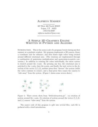
“ride away” from the system. (Figure 1 shows some screen shots.)
Figure 1: Three screen shots from “littlecubesystem.py”: (a) rotation of
system around the z-axis, (b) rotation of system around the vector (5, 5, 2),
and (c) camera “rides away” from the system.
The source code of this program is split into several files; each file is
prefaced with a brief introduction.
1
2. This program relies specifically on Allegro 4.2.2 and
Dependencies.
Alpy 0.1.3 (it doesn’t seem to work with later versions), and Python 2.2
or greater. It should also be noted that I have only attempted to use this
program under Linux; I have no idea how well it would run under other
operating systems.
Allegro is a game, graphics and sound library that can be downloaded
from “http://alleg.sourceforge.net”. Several years ago a friend introduced
me to this library, and I like this library enough that I wanted to use it
for this project. In particular, Allegro provides a system for doing graphics
independent of the X Window system; since I had a desire (and still do,
actually) to put together an “open source” game console, creating a game
that didn’t use the overhead of the X Window system was very appealing.
Alpy is a package that provides bindings that I needed to use Allegro un-
der Python. Although these bindings don’t provide complete Allegro func-
tionality, they provide enough for me to work on this project. This package
can be downloaded at “http://pyallegro.sourceforge.net/alpy.php”, but be-
cause the newer version of Alpy doesn’t seem to work, it is necessary to
download an older version. To do so,
1. Scroll down to the section “Alpy 0.1.3 released”,
2. and click on the link “SourceForge’s file section”,
3. Scroll down and select “alpy-0.1.3”, and then decide which version
(.tar.gz or .zip) to download.
This package also requires Python 2.2 or greater. I chose to write this
program in Python because Python is a powerful yet easy-to-learn scripting
language that can be mixed relatively easily with C or C++. These features
make Python ideal as a prototyping language.
Future Goals for This Project. Having completed my camera ap-
paratus, I had hoped to make a wireframe chess piece, and then expand my
3D engine to include the following:
• Filling in of faces, and establishing appropriate drawing orders;
• Clipping and “distance fog”, to limit the number of polygons needed
to write to the screen;
2
3. • A physics engine, to realistically represent momentum, inertia, gravity,
rotational momentum, and so forth;
• Ability to move characters using a keyboard or joystick.
• Re-implementation of the classes to make objects easier to manipulate;
• Re-implementation of crucial portions in C++, to increase the speed
of the program.
In particular, I hope to expand this engine to become a computer game. My
goals in this regard were delayed as my graduate studies intensified.
Since high school I have always been interested
Personal Remarks.
in programming computer games. It is a little unfortunate that my inter-
est began in a time when 3D game engines were coming of age; my career
wouldn’t be able to mature with the industry. I couldn’t start my career
with a simple yet popular game like Pong (that, despite its simplicity, taxed
the available computing resources at the time) and continue writing more
complex programs, eventually leading up to a game like Doom III. Instead,
I have the desire (and the far more difficult goal) to write a full-fledged 3D
computer game!
Even so, I have always had an affinity with writing 3D programs; this
field fuses together computer programming with linear algebra in a concrete,
visual way. Due to my studies as a graduate student, however, and the
complexities of such a project, I simply have not had the time to pursue this
project as much as I would have liked.
“math3d.py”. This module conveniently brings together all the modules
I wrote for my 3D graphics engine. It’s rather boring! I decided to put it
first, as a sort-of table of contents of the rest of the modules.
# This module represents all the three -
# dimensional math things I ’ll need to create a
# three - dimensional model of a given world .
# I ’m importing things quot; from etc import *quot; so that
3
4. # this file won ’t be excessively long .
# These are basic datatypes ...
from ttable import *
from vertex import *
from matrix import *
# Here is our first inheritable class !
from movable import *
# Finally , we import our wireframe and camera
# classes and functions .
from wf import *
from camera import *
“ttable.py”. In this module, I define special trigonometric functions that
rely on table lookups rather than direct computation; I use “bradians” as an
alternative to radians or degrees to take advantage of the binary nature of
computers: one byte will contain all possible bradian values.
# ttable . py
# The purpose of this module is to define sin , cos ,
# tan , cot , etc by using quot; bradians quot; (1 bradian is
# 1/256 of a circle ), and then make a table for
# looking up these values .
# This should be faster than calculating sin , cos ,
# etc directly
# As a result of this , too , all my graphics
# functions will be have to take bradians , as well .
# To remind me of this , I ’ll use the term quot; beta quot;
# instead of quot; theta quot; to designate angles .
4
5. from math import sin , pi
sinfile = quot; sintable . dat quot;
sintable = []
try :
# open table . dat
tablefile = file ( sinfile , ’r ’)
f o r i in tablefile :
sintable . append ( float ( i ))
i f len ( sintable ) != 256:
r a i s e AttributeError ,
quot; current file is not a bradian sin table ! quot;
tablefile . close ()
except IOError :
# if . sintable . dat doesn ’t exist , or is
# corrupted , then create a new table ...
tablefile = file ( sinfile , ’w ’)
f o r i in range (256):
sintable . append ( sin ( i * pi /128.0))
p r i n t >> tablefile , sintable [ i ]
tablefile . close ()
# so now we go to the trig functions :
def tsin ( beta ):
return sintable [ int ( round ( beta )) % 256]
def tcos ( beta ):
return sintable [ int (64 - round ( beta )) % 256]
def ttan ( beta ):
# in all honesty , this would be slightly faster
# if we were to look up the values rather than
# resort to tsin and tcos ...
return tsin ( beta )/ tcos ( beta )
def tcot ( beta ):
# this has the same caveat as ttan
5
6. return tcos ( beta )/ tsin ( beta )
# Note that I won ’t worry about defining secant or
# cosecant . I don ’t think they ’re needed , at least
# not for now !
“vertex.py”. This module contains everything convenient for working
with vertices (represented as vectors), edges and faces. I first define the
vector class and vector algebra, then go on to define edges and faces, and
end by defining two useful “palettes” of colors.
# vertex . py
# This module contains all the things for creating
# and using vertices ... starting with vector , and
# going on to edge and face .
# Observe two things , though :
# First , I tried to keep small numbers as quot; zeros quot;
# by rounding divisions ( see __div__ and norm ) to
# five significant digits . So if a number is one
# like 5.2 e -6 , it will be rounded to 0.
# Second , to make sure that division works
# appropriately , I initialized the original vector
# with float ( etc ).
from math import sqrt
c l a s s vector ( object ):
def __init__ ( self , x , y , z , w =1):
# Note that despite the w , these are
# still 3D vectors .
self . x = float ( x )
self . y = float ( y )
self . z = float ( z )
self . w = float ( w )
6
7. def __add__ ( self , v ):
x = self . x + v . x
y = self . y + v . y
z = self . z + v . z
return vector (x , y , z )
def __sub__ ( self , v ):
x = self .x - v . x
y = self .y - v . y
z = self .z - v . z
return vector (x , y , z )
def __mul__ ( self , s ):
x = self . x * s
y = self . y * s
z = self . z * s
return vector (x , y , z )
def __div__ ( self , s ):
x = round ( self . x /s , 5)
y = round ( self . y /s , 5)
z = round ( self . z /s , 5)
return vector (x , y , z )
def __neg__ ( self ):
return vector ( - self .x , - self .y , - self . z )
def dot ( self , v ):
return self . x * v . x + self . y * v . y + self . z * v . z
def cross ( self , v ):
x = self . y * v . z - self . z * v . y
y = self . z * v . x - self . z * v . z
z = self . x * v . y - self . y * v . x
return vector (x , y , z )
def dist ( self ):
return round ( sqrt ( self . x * self . x + self . y * self . y
+ self . z * self . z ) , 5)
def norm ( self ):
return self / round ( self . dist () , 5)
7
8. def __str__ ( self ):
return quot; < %s , %s , % s > ( w = % s ) quot; %
( self .x , self .y , self .z , self . w )
# Here are a few vector constants that are nice to
# define : in particular , note that [ Left , Up , Fwd ]
# is a left - hand coord system , while [ Right , Up , Fwd ]
# represents a right - hand one .
Zero = vector (0 , 0 , 0)
Up = vector (1 , 0 , 0)
Left = vector (0 , -1 , 0)
Right = vector (0 , 1 , 0)
Fwd = vector (0 , 0 , 1)
# I defined these functions separately from the
# classes because it seems more natural to say
# quot;x = dist (v )quot; rather than quot;x = v. dist ()quot; , etc .
def dist ( v ):
return sqrt ( v . x * v . x + v . y * v . y + v . z * v . z )
def norm ( v ):
return v / round ( dist ( v ) , 5)
def orthonorm (x , y , z ):
quot; quot; quot; Returns a tuple of orthonormal vectors via the
Gramm - Schmidt process . See Apostal ’s Linear
Algebra , pg . 111 , or another LinAlg book for
the theoretical background of this process . quot; quot; quot;
q1 = x
q2 = y - q1 *( y . dot ( q1 )/ q1 . dot ( q1 ))
q3 = z - q1 *( z . dot ( q1 )/ q1 . dot ( q1 )) -
q2 *( z . dot ( q2 )/ q2 . dot ( q2 ))
return ( q1 . norm () , q2 . norm () , q3 . norm ())
# Now that we have our vector defined , we could
# define the things that will make our vector a
# vertex .
8
9. c l a s s edge ( object ):
def __init__ ( self , v1 , v2 , color = ’ none ’ ):
self . v1 = v1
self . v2 = v2
self . color = color
def __str__ ( self ):
return quot; [ %s , % s ] % s quot; % ( self . v1 , self . v2 ,
self . color )
c l a s s face ( object ):
def __init__ ( self , vertices , color = ’ none ’ ):
# This is a list of indices for vertices .
self . vertices = vertices
self . color = color
def __str__ ( self ):
return quot; % s <%s > quot; % ( self . vertices , self . color )
# These colors are included with vertices so that
# faces and edges can have colors .
egacolors = { ’ none ’: -1 , ’ black ’:0 , ’ blue ’:1 ,
’ green ’:2 , ’ cyan ’:3 , ’ red ’:4 , ’ purple ’:5 ,
’ brown ’:6 , ’ gray ’:7 , ’ brightblack ’:8 ,
’ darkgray ’:8 , ’ brightblue ’:9 , ’ brightgreen ’ :10 ,
’ brightcyan ’ :11 , ’ brightred ’ :12 , ’ pink ’ :12 ,
’ brightpurple ’ :13 , ’ brightbrown ’ :14 , ’ yellow ’ :14 ,
’ brightgray ’: 15 , ’ white ’ :15 }
# This defines shades of gray
bwcolors = {}
f o r i in range (0 , 16):
bwcolors [ ’ black % s ’ % ( i )] = i +16
“matrix.py”. This next module defines some matrix algebra, and produces
9
10. various matrices (including camera matrices) that would be useful in working
with computer graphics.
# matrix . py -- A module for the creation of matrices
# for purposes of projecting things to the screen .
# Eventually these should be ported to C or C ++ for
# better efficiency !
# Note that while I ’ve been ignoring exceptions , I
# should probably create a MatrixException class
# that would include quot; AddException quot; or
# quot; MultException quot; when invalid matrix arithmetic
# is attempted
# Also note that this module needs the following :
# ttable .py , for bradian trig table functions
# vertex .py , for vectors
from ttable import *
from vertex import *
c l a s s matrix ( object ):
def __init__ ( self ):
self . mx = []
# Note that I decided to do away with __add__ and
# __sub__ , since they aren ’t used much in computer
# graphics .
def __mul__ ( self , m ):
quot; quot; quot; Multiplies two matrices , or a matrix and scalar .
This should also throw an exception if the
two matrices provided cannot be multiplied
together . ( This isn ’t implemented , though .
As it currently stands , it allows multi -
plication of matrices that are sufficiently
similar ... that is , any two matrices for
which the index doesn ’t go out of range
10
11. before the algorithm is finished .
For example , it ’s possible to quot; multiply quot;
two 3 x2 matrices .) quot; quot; quot;
r = matrix ()
f o r i in range (0 , len ( self . mx )):
r . mx . append ([])
f o r j in range (0 , len ( m . mx [0])):
r . mx [ i ]. append (0)
f o r k in range (0 , len ( m . mx )):
r . mx [ i ][ j ] += self . mx [ i ][ k ]* m . mx [ k ][ j ]
return r
def proj ( self , v ):
quot; quot; quot; Multiplies a matrix with a vector .
I call it quot; proj quot; because it will be how I
will project a vector using my camera
matrix . quot; quot; quot;
x = float ( self . mx [0][0]* v . x + self . mx [0][1]* v . y +
self . mx [0][2]* v . z + self . mx [0][3]* v . w )
y = float ( self . mx [1][0]* v . x + self . mx [1][1]* v . y +
self . mx [1][2]* v . z + self . mx [1][3]* v . w )
z = float ( self . mx [2][0]* v . x + self . mx [2][1]* v . y +
self . mx [2][2]* v . z + self . mx [2][3]* v . w )
w = float ( self . mx [3][0]* v . x + self . mx [3][1]* v . y +
self . mx [3][2]* v . z + self . mx [3][3]* v . w )
# We might as well return a homogeneous vector !
i f w == 0:
return vector (x , y , z , 1.0)
else :
return vector ( x /w , y /w , z /w , 1.0)
def __str__ ( self ):
11
12. quot; quot; quot; Creates a string representation of a matrix . quot; quot; quot;
string = ’ ’
f o r i in self . mx :
string += ’[ % s ] n ’ % i
return string
def getproj ( left , right , top , bottom , near , far ):
quot; quot; quot; Takes values given and returns a projection matrix .
This function is based on the general description
given in 3 D Game Engine Design , p . 86... This
matrix also incorporates the two equations
( Sx -1)*( x +1)/2 and ( Sy -1)*( y +1)/2.
that will project the vectors onto the screen .
( As described in 3 D Game Engine Design , the matrix
doesn ’t do this .) quot; quot; quot;
Sx = right - left
Sy = top - bottom
Sz = far - near
# To translate the point to screen coordinates ,
# I ’ll need the following constants :
PSx = ( Sx -1)/2
PSy = ( Sy -1)/2
mx = matrix ()
mx . mx = [
[2* near / Sx * PSx , 0 , ( right + left )/ Sx - PSx , 0] ,
[0 , 2* near / Sy * PSy , ( top + bottom )/ Sy - PSy , 0] ,
[0 , 0 , -( far + near )/ Sz , -2*( far * near )/ Sz ] ,
[0 , 0 , -1 , 0] ]
return mx
def getfovproj ( left , right , top , bottom , near , beta ):
quot; quot; quot; Takes values given and returns a fov projection matrix .
12
13. This function is based on the technique described
in Linux 3 D Programming , p . 381. Unlike the
original setproj () , the vectors returned are given
as screen coordinates . quot; quot; quot;
Sy = float ( top - bottom )
Sx = float ( right - left )
fov = tcot ( beta /2)
mx = matrix ()
mx . mx = [ [( Sx /2)* fov , 0 , Sx /2 , 0] ,
[0 , -( Sy /2)* fov *( Sx / Sy ) , Sy /2 , 0] ,
[0 , 0 , near , 1] ,
[0 , 0 , 1 , 0] ]
p r i n t quot; Sy =% s , Sx =% s , fov =% s quot; % ( Sy , Sx , fov )
p r i n t mx
return mx
# Here we assume that left , up , fd form an
# orthonormal basis . I would expect that
# interesting things would happen if these
# vectors - weren ’t - orthonormal ! but I haven ’t
# tried it yet , to see what would happen .
def getcam ( left , up , fd , eye ):
quot; quot; quot; Takes given vectors and returns a coord - changing matrix .
That is , a matrix that transfers quot; world quot;
coordinates to camera ones , and then translates
them via the eye to the right spot . quot; quot; quot;
mx = matrix ()
mx . mx = [ [ left .x , left .y , left .z , - left . dot ( eye )] ,
[ up .x , up .y , up .z , - up . dot ( eye )] ,
[ fd .x , fd .y , fd .z , - fd . dot ( eye )] ,
[0 , 0 , 0 , 1] ]
return mx
# Here we assume that axis is normalized ... but pos
# shouldn ’t be ! The default is the identity matrix ...
def getworld ( beta =0 , axis = Up , pos = Zero ):
13
14. quot; quot; quot; Takes values and returns a rotation / translation matrix .
In particular , it rotates the object beta bradians
around given axis ( it needs to be pre - normalized )
and then translates the object via pos . quot; quot; quot;
# This is the rotation quaternion ...
w = tcos ( beta /2)
x = tsin ( beta /2)* axis . x
y = tsin ( beta /2)* axis . y
z = tsin ( beta /2)* axis . z
# Here are a few calculations that will be used to
# create our special matrix !
xx2 = 2* x * x ; yy2 = 2* y * y ; zz2 = 2* z * z
wx2 = 2* w * x ; wy2 = 2* w * y ; wz2 = 2* w * z
xy2 = 2* x * y ; xz2 = 2* x * z ; yz2 = 2* y * z
# Note that , since I ’m doing a rotate first , and
# then a translate , I can just tack pos on as the
# last column . Otherwise the last column would be
# rather messy !
mx = matrix ()
mx . mx = [ [1 - yy2 - zz2 , xy2 + wz2 , xz2 - wy2 , pos . x ] ,
[ xy2 - wz2 , 1 - xx2 - zz2 , yz2 + wx2 , pos . y ] ,
[ xz2 + wy2 , yz2 - wx2 , 1 - xx2 - yy2 , pos . z ] ,
[0 , 0 , 0 , 1] ]
return mx
def gettrans ( pos ):
mx = matrix ()
mx . mx = [ [1 , 0 , 0, pos . x ] ,
[0 , 1 , 0, pos . y ] ,
[0 , 0 , 1, pos . z ] ,
[0 , 0 , 0, 1] ]
return mx
def getskew (r , s , t , pos = Zero ):
14
15. mx = matrix ()
mx . mx = [ [r , 0, 0, pos . x ] ,
[0 , s, 0, pos . y ] ,
[0 , 0, t, pos . z ] ,
[0 , 0, 0, 1] ]
return mx
“movable.py” This module creates the class that is the foundation for all
my 3D objects.
# movable . py -- This module defines a class from
# which 3D objects , such as cameras and wireframes ,
# can inherit . In doing so , they become manipulable
# by various means ... particularly by matrices .
from vertex import *
from matrix import *
c l a s s movable ( object ):
def __init__ ( self , beta =0 , axis = Up , pos = Zero ):
quot; quot; quot; Sets angle , axis vector , and position vector .
Since rotations require a normalized axis , we
take the norm of the axis we want to rotate by .
Note that the angle is given in bradians . quot; quot; quot;
self . beta = beta
self . axis = axis . norm ()
self . pos = pos
self . world = getworld ( self . beta , self . axis ,
self . pos )
# The nice thing about the following methods is
# that , once the world matrix is set , the points
15
16. # will be moved quot; automatically quot; when they are
# projected .
# Also , if further things are needed ( like
# multiplying with other matrices ) these could
# be over - ridden ... but after things are set ,
# we don ’t have to worry about the object again .
def setangle ( self , beta ):
self . beta = beta
self . world = getworld ( self . beta , self . axis ,
self . pos )
def setaxis ( self , axis ):
self . axis = axis . norm ()
self . world = getworld ( self . beta , self . axis ,
self . pos )
def setrot ( self , beta , axis ):
self . beta = beta
self . axis = axis . norm ()
self . world = getworld ( self . beta , self . axis ,
self . pos )
def settrans ( self , pos ):
self . pos = pos
self . world = getworld ( self . beta , self . axis ,
self . pos )
def setmove ( self , beta , axis , pos ):
self . __init__ ( beta , axis , pos )
def getorient ( self ):
return ( self . beta , self . axis , self . pos )
# I initially tried to add methods like quot; addrot ()quot; ,
# but the quaternion math involved was too complex .
# Part of the problem is that this class is based
# on angle - axis rotations rather than quaternion
# rotations , so I couldn ’t take advantage of
# combining rotations via quaternionic
16
17. # multiplication .
# Eventually I should probably re - write this so
# that I could use quaternions instead of angle - axis
# rotations . I chose to ignore this for now ,
# though , and focus on getting the camera to work .
“wf.py”. This module provides the class that reads in data files and uses
them to create wireframe objects.
# This module should contain everything I need to
# create a wireframe object .
# This is the first major step in creating my game
# engine .
# Special note : For some reason , in
# quot; wireframe . __init__ quot;, the function quot; re . sub quot;
# insists on adding ’’ whenever there ’s whitespace .
# I don ’t know if this is a ’ feature ’ or if I ’m
# doing something wrong there ... but it ’s nonetheless
# annoying .
from vertex import *
from movable import *
import re
# Finally , I create the infamous wireframe class !
c l a s s wireframe ( movable ):
’ The class that represents 3 D objects . ’
def __init__ ( self , filename , beta =0 , axis = Up ,
pos = Zero ):
movable . __init__ ( self , beta , axis , pos )
self . vertices = []
17
18. self . edges = []
self . faces = []
# Each stage of processing the data file has a
# special function that will be referenced in
# a special loop .
def vertices ( ln ):
’ Converts a list to a vertex format for wireframe . ’
v = vector ( float ( ln [0]) , float ( ln [1]) ,
float ( ln [2]))
self . vertices . append ( v )
def edges ( ln ):
’ Converts a list to an edge format for wireframe . ’
e = edge ( int ( ln [0]) , int ( ln [1]) , ln [2])
self . edges . append ( e )
def faces ( ln ):
’ Converts a list to a face format for wireframe . ’
vlist = []
f o r n in ln [: -1]:
vlist . append ( int ( n ))
self . faces . append ( face ( vlist , ln [ -1]))
def finished ( ln ):
pass
stage = [ vertices , edges , faces , finished ]
myfile = file ( filename )
i=0
f o r eachline in myfile :
oldline = eachline
eachline = re . sub ( ’ #.* ’ , ’ ’ , eachline )
# to remove comments that start with ’#’
eachline = re . split ( ’ s + ’ , eachline )
# the ’+’ is needed to keep lots of ’’
# from being added
# since sub insists on putting lots of ’’ in
# the lists , we need to add this loop .
mylist = []
18
19. f o r item in eachline :
i f item : mylist . append ( item )
i f mylist :
i f mylist [0] == ’ end ’:
# if we reach the end of one stage , go to
# the next
i +=1
else :
# Add vertex , edge or face according to
# the right stage
stage [ i ]( mylist )
def __str__ ( self ):
string = ’ ’
f o r vtx in self . vertices :
string += str ( vtx ) + ’ n ’
f o r edge in self . edges :
string += str ( edge ) + ’ n ’
f o r face in self . faces :
string += str ( face ) + ’ n ’
return string
“camera.py”. This next module defines two different cameras that could
be used to render a scene. This is the core of the 3D graphics engine.
# camera . py -- This is the culmination of all that
# I ’ve been working on for the last couple of days :
# the two different camera systems ! Naturally , it
# depends on several libraries :
from vertex import *
from matrix import *
from movable import *
from wf import *
19
20. import alpy
# This definition will likely call for massive
# simplification . For example , I doubt that it ’s
# necessary to specify coords , since they ’ll be
# changed by changing the position anyway .
# The only possible exception would be
# quot; coords [3] == eye quot;, although quot; position [3] == pos quot;
# alters the position of eye ...
Sx = 320; Sy = 400
Near = 500; Far = 10000; Fov = 45*(256/360)
# That is , beta is 45 degrees .
projmx = { ’ standard ’: getproj , ’ fov ’: getfovproj }
# note that type can be specified at the very end ...
# default is ’ standard ’.
c l a s s camera ( movable ):
def __init__ ( self , sx = Sx , sy = Sy , near = Near ,
farfov = Far , beta =0 , axis = Up ,
pos = Zero , camtype = ’ standard ’ ):
quot; quot; quot; This creates self . world . quot; quot; quot;
# Position needs to be negative , because the
# only things it affects are quot;- coords . dot ( eye )quot; ,
# where coords are the three coordinate
# vectors of the camera .
# Since eye is the thing that gets translated ,
# we need quot;- coords . dot ( eye + pos ) ==
# coords . dot (- eye - pos )quot;.
movable . __init__ ( self , beta , axis , - pos )
self . Sx = sx ; self . Sy = sy
self . near = near ; self . farfov = farfov
20
21. self . top = top = sy /2;
self . bottom = bottom = - self . top
self . right = right = sx /2
self . left = left = - self . right
# Until further notice , neither the projection
# nor the film matrices will be changing ! and
# the coordinate matrix will never change ...
# Note : fovproj uses a right - hand coordinate
# system . ( This would probably be easy to
# change , though ... by changing the last row
# of fovproj from [0 ,0 ,1 ,0] to [0 ,0 , -1 ,0]
self . proj = projmx [ camtype ]( left , right , top ,
bottom , near , farfov )*
getcam ( Left , Up , Fwd , vector (0 , 0 , - near ))
self . film = alpy . Bitmap ( sx , sy , 8)
# Please remember at all times that
# self . proj = getproj ()* getcam ()
# ... unless proj changes , there is no reason
# to keep these separate .
# Also note that self . world correctly positions
# the coordinate / eye system .
self . camera = self . proj * self . world
# We will have to call this ourselves if we change
# the projection matrix without changing the
# position of the camera ...
def reorient ( self ):
self . camera = self . proj * self . world
# We need to overload the following functions :
def setangle ( self , beta ):
21
22. movable . setangle ( self , beta )
self . reorient ()
def setaxis ( self , axis ):
movable . setaxis ( self , axis )
self . reorient ()
def setrot ( self , beta , axis ):
movable . setrot ( self , beta , axis )
self . reorient ()
# Just a brief reminder : -pos needs to be
# negative to translate quot; eye quot; correctly .
def settrans ( self , pos ):
movable . settrans ( self , - pos )
self . reorient ()
def setmove ( self , beta , axis , pos ):
movable . setmove ( self , beta , axis , - pos )
self . reorient ()
# We might also want to add another method or two
# to alter the matrices :
# def setproj () and variants
# def seteye ()
def draw_wf ( self , wf ):
# This line should be
# quot; viewport = proj * camera * wf . world quot;
# but for now this isn ’t a part of wireframe .
viewport = self . camera * wf . world
vtcs = []
f o r i in wf . vertices :
vtx = viewport . proj ( i )
# For non - homogeneous vertices :
# vtcs . append ([319*( vtx .x/ vtx .e -1)/2 ,
# 399*( vtx .y/ vtx .e -1)/2])
vtcs . append ([ vtx .x , vtx . y ])
# For non - homogeneous vertices :
# vtcs . append ([ vtx .x/ vtx .e , vtx .y/ vtx .e ])
22
23. # Now let ’s draw the lines !
f o r i in wf . edges :
self . film . line ( vtcs [ i . v1 ][0] , vtcs [ i . v1 ][1] ,
vtcs [ i . v2 ][0] , vtcs [ i . v2 ][1] ,
egacolors [ i . color ])
def display ( self ):
self . film . blit ()
“littlecubesystem.py”. This file uses my camera, as implemented in
the previous modules, and displays the rotating cubes.
# !/ usr / local / bin / python2 .5
# In this Python program , I test my quot; camera quot; by
# drawing a coordinate axis and several rotating
# cubes . This program depends on Allegro 4.2.2
# and alpy 0.1.3 , as well as Python 2.2 or greater .
import sys
import alpy
# This module imports all the little modules I will
# need for this program .
import math3d
# First , we need to initialize the graphics system .
alpy . allegro_init ()
alpy . install_keyboard ()
try :
alpy . set_gfx_mode ( alpy . GFX_AUTODETECT , 320 , 400)
except :
alpy . set_gfx_mode ( alpy . GFX_TEXT , 0 , 0)
p r i n t ’ unable to set any graphic mode ’
23
24. sys . exit (1)
alpy . set_palette ( alpy . default_palette )
alpywhite = alpy . makecol (255 , 255 , 255)
alpyblack = alpy . makecol (0 , 0 , 0)
# We can now create a camera object . This will be
# what we use to draw things to the screen .
camera = math3d . camera ()
# We will be rotating eight different cubes . The
# following vectors will be used to position each
# cube .
vec = math3d . vector
positions = [ vec (50 , 50 , 50) , vec ( -50 , 50 , 50) ,
vec ( -50 , -50 , 50) , vec (50 , -50 , 50) ,
vec (50 , 50 , -50) , vec ( -50 , 50 , -50) ,
vec ( -50 , -50 , -50) , vec (50 , -50 , -50) ]
cube = []
f o r i in range (8):
cube . append ( math3d . wireframe ( ’ littlecube . dat ’ ,
pos = positions [ i ] , axis = positions [( i +1)%8]))
# For visual reference , we will also draw a
# coordinate axis .
coords = math3d . wireframe ( ’ coords . dat ’)
camera . film . clear ( alpywhite )
# Rotate cubes around Fwd axis
i=0
while 1:
camera . film . clear ( alpywhite )
camera . draw_wf ( coords )
camera . setrot (i , math3d . Fwd )
24
25. f o r v in cube :
camera . draw_wf ( v )
v . setangle ( i )
i = ( i +1)%256
i f alpy . keypressed ():
alpy . readkey ()
break
camera . display ()
# Rotate cubes around Left axis
i=0
while 1:
camera . film . clear ( alpywhite )
camera . draw_wf ( coords )
camera . setrot (i , math3d . Left )
f o r v in cube :
camera . draw_wf ( v )
v . setangle ( i )
i = ( i +1)%256
i f alpy . keypressed ():
alpy . readkey ()
break
camera . display ()
# Rotate boxes around Up axis
i=0
while 1:
camera . film . clear ( alpywhite )
camera . draw_wf ( coords )
camera . setrot (i , math3d . Up )
f o r v in cube :
camera . draw_wf ( v )
25
26. v . setangle ( i )
i = ( i +1)%256
i f alpy . keypressed ():
alpy . readkey ()
break
camera . display ()
# Rotate boxes around a diagonal axis
# ( subject to change )
i=0
while 1:
camera . film . clear ( alpywhite )
camera . draw_wf ( coords )
camera . setrot (i , math3d . vector (5 ,5 ,2))
f o r v in cube :
camera . draw_wf ( v )
v . setangle ( i )
i = ( i +1)%256
i f alpy . keypressed ():
alpy . readkey ()
break
camera . display ()
# Just rotate the cubes
i=0
while 1:
camera . film . clear ( alpywhite )
camera . draw_wf ( coords )
f o r v in cube :
camera . draw_wf ( v )
v . setangle ( i )
26
27. i = ( i +1)%256
i f alpy . keypressed ():
alpy . readkey ()
break
camera . display ()
# Let the cubes quot; ride off quot; in the distance
i=0
while 1:
camera . film . clear ( alpywhite )
camera . draw_wf ( coords )
camera . settrans ( math3d . vector (0 , 0 , -i * i ))
f o r v in cube :
camera . draw_wf ( v )
v . setangle ( i )
i = i +1
i f alpy . keypressed ():
alpy . readkey ()
break
camera . display ()
camera . display ()
alpy . readkey ()
The data file “littlecube.dat”. This contains the information needed
to create a cube. The comments in this file also explain how to write (or
generate via software) other wireframe files.
# Cube Wireframe file
# First we list the vertices, one per line.
# Note that the order of these vertices are crucial!
27
28. -10 -10 -10 # v0 # Note that all comments begin with
-10 10 -10 # a ’#’ and then go to the end of the line
10 10 -10
10 -10 -10
-10 -10 10 # v4
-10 10 10
10 10 10
10 -10 10 # v8
end vertices # each section needs a lowercase ’end’
# Now we can add our edges:
0 1 blue # e0 # edges don’t need any particular order...
1 5 blue # e5 # These labels were provided to help me create
5 4 blue # e8 # this file: since I created it by hand, I
4 0 blue # e4 # inputed this information from a hand-drawn
# picture of a cube, with labeled vertices,
1 2 green # edges and faces.
2 6 green
6 5 green
6 7 green
23 green
03 green
47 green
37 green
end edges
# finally we add some faces, noting that each face needs to
# be on a line by itself...
0 1 5 4 blue # f0
1 2 6 5 red
0 1 2 3 red
# 0 3 7 4 red
4 5 6 7 red
# 3 2 6 7 red
end faces
At this point, there’s nothing else for my wireframe class to
28
29. read, so I could write anything here....
For example, I can use this space to point out that by
commenting out the two faces that I did, they shouldn’t
appear when I finally draw my cube.
This data file provides the coordinate
The data file “coords.dat”.
axis that is drawn by the program.
# Coordinate Wireframe file
# First we list the vertices, one per line.
# Note that the order of these vertices are crucial!
000 # origin
50 0 0 # x-axis
0 50 0 # y-axis
0 0 50 # z-axis
0 0 -50 # -z-axis
end vertices # each section needs a lowercase ’end’
# Now we can add our edges:
0 1 blue
0 2 red
0 3 green
0 4 black
end edges
# There are no faces.
end faces
“sintable.dat”. For completeness, the data for the bradian sine table is
29
30. also provided, although this file is just a list of computer-generated numbers.
It starts with the bradian sine of 0, and then increments up to the bradian
sine of 255.
In the original text file, these numbers are in a single column; to save
space (and to make it more readable), these numbers are shown here in three
columns.
0.0 0.689540544737 0.998795456205
0.0245412285229 0.707106781187 0.999698818696
0.0490676743274 0.724247082951 1.0
0.0735645635997 0.740951125355 0.999698818696
0.0980171403296 0.757208846506 0.998795456205
0.122410675199 0.773010453363 0.997290456679
0.146730474455 0.788346427627 0.995184726672
0.17096188876 0.803207531481 0.992479534599
0.195090322016 0.817584813152 0.989176509965
0.219101240157 0.831469612303 0.985277642389
0.242980179903 0.84485356525 0.980785280403
0.266712757475 0.85772861 0.975702130039
0.290284677254 0.870086991109 0.970031253195
0.313681740399 0.881921264348 0.963776065795
0.336889853392 0.893224301196 0.956940335732
0.359895036535 0.903989293123 0.949528180593
0.382683432365 0.914209755704 0.941544065183
0.405241314005 0.923879532511 0.932992798835
0.42755509343 0.932992798835 0.923879532511
0.449611329655 0.941544065183 0.914209755704
0.471396736826 0.949528180593 0.903989293123
0.49289819223 0.956940335732 0.893224301196
0.514102744193 0.963776065795 0.881921264348
0.534997619887 0.970031253195 0.870086991109
0.55557023302 0.975702130039 0.85772861
0.575808191418 0.980785280403 0.84485356525
0.595699304492 0.985277642389 0.831469612303
0.615231590581 0.989176509965 0.817584813152
0.634393284164 0.992479534599 0.803207531481
0.653172842954 0.995184726672 0.788346427627
0.671558954847 0.997290456679 0.773010453363
30