SlideShare a Scribd company logo
1 of 5
SwitchingVectorRegionState of the PhasePhase APhase BPhase C1011001VdcGndPWM1001102VdcPWMGnd1100103PWMVdcGnd0100114GndVdcPWM0110015GndPWMVdc0011016PWMGndVdc<br />Permanent magnet motors <br />Enlarge this pictureleft000Fig. 4. Ideal trapezoidal commutation.<br />In contrast to the ACIM, permanent magnet machines do not rely on induced AC currents to provide rotor magnetization. Fixed permanent magnets on the rotor take care of that task. As a result, permanent magnet motors use less overall current for a given torque, and provide superior performance down to zero speed, unlike the ACIM. This also means that permanent magnet motors have higher electrical efficiency than induction motors. Permanent magnet motors are synchronous, so there is no slip between the electrical and mechanical rotation speed. One of the most commonly used permanent magnet motors is the brushless DC (BLDC) motor.  Its name is a bit of a misnomer, as it is not truly a DC machine. The name was applied more than 30 years ago when it was compared to the brush-type DC motor for its similar speed-torque characteristic. At issue was mechanical commutation (brushes and commutator) versus electrical commutation. So the BLDC motor behaves like a DC (brush) motor as opposed to an AC (induction) motor, but the applied winding voltages are really AC for both. <br />Trapezoidal vs. sinusoidal commutation <br />Enlarge this pictureright000Fig. 5. Sinusoidal commutation.<br />Both trapezoidal six-step (BLDC) and sinusoidally commutated motors (permanent magnet AC or PMAC) most commonly have three stator windings arranged in a 3-wire WYE configuration as shown in Fig. 3. Both motor types are also driven from the same 3-phase Voltage-Source Inverter (VSI) topology also shown in Fig. 3. Phase-currents for both types of motors are controlled by pulse-width modulation of the applied voltage on each phase. Both BLDC and PMAC motors clearly have a lot in common. A casual observer might not even see any difference in the overall construction of these two types of motors. The difference is in the “torque function” of each motor type, and how current is driven into the windings. If each motor type is spun, and the resulting back EMF examined on an oscilloscope, it would be seen that the BLDC motor has a flat-topped trapezoidal voltage, and the PMAC motor has a sinusoidal shape. In order to derive smooth torque from these motors, the applied current should be the same shape as the back EMF. In the case of the BLDC motor, current is applied to only two of the three windings at a time.  During one commutation interval, a steady current is injected into one motor lead, returning through a second lead – and the third lead is open. (It can be used for position estimate by measuring zero-cross). As the motor shaft rotates, the next set of windings is energized, sequencing through all six possible combinations (thus the name six-step) – at which point the motor has gone through one electrical revolution (fractional mechanical revolution depending on how many winding “poles” the motor has). An important implication of this commutation method is that only two of the six inverter switches are conducting at any time, and only two of the three windings carry current at any time. These two factors affect distribution of thermal loads in both the inverter and the motor. Trapezoidal commutation is depicted in Fig. 4. In contrast, for a sinusoidally commutated PMAC motor, each of the three phases of the inverter is modulating (PWM) all the time, driving three out-of-phase sinusoidal currents into each winding. Sinusoidal commutation is depicted in Fig. 5. From an application standpoint, the biggest difference between trapezoidal and sinusoidal commutation is that sinusoidal commutation delivers absolutely smooth torque at any rotational angle or speed. Torque disturbances due to commutation, combined with magnetostriction in the stator generate acoustical commutation noise in BLDC motors. This effect is absent in sinusoidally commutated PMAC motors, making them virtually silent (except for possible PWM noise). Quiet operation is often a very important consideration for appliances. <br />Controlling synchronous motors <br />Enlarge this pictureleft000Fig. 6. Sensorless PMAC controller.<br />Based on the previous paragraph, it may seem that sinusoidal commutation would always be the preferred choice because of the smooth torque and lack of commutation noise. However, there is an additional control burden to consider as well. Simply put, trapezoidal control is simpler to implement than sinusoidal control. This added complexity must be considered in the decision of which motor and control type is best for an application. For BLDC motors, a straightforward PWM current loop can control winding current, while commutation is handled by position sensors (Hall-effect or shaft encoder) or position estimate from winding voltage (from zero-crossing of unused winding). The current loop (which equals torque loop) is then controlled by a velocity control loop, and even an outer position control loop. Top speed of BLDC motor drive is reached when the motor back-EMF reaches the drive bus voltage. At that operating point, the drive cannot deliver enough current to increase motor speed, even at 100 percent duty-cycle. Sinusoidal commutation offers some additional benefits. Simple open-loop variable-frequency sinusoidal drive control is used for ACIM, but not for permanent magnet synchronous motors.  PMAC motors are driven with closed-loop sinusoidal current control. Maximum performance and efficiency is obtained with field-oriented control. Field orientation requires rotor position information, either through direct measurement (encoder) or estimation (sensorless). Motor currents are modeled in a two-axis format with orthogonal direct (D) and quadrature (Q) axis components. The D-axis vector controls the magnetization of the motor, independently of the Q-axis (torque-producing) vector. In normal operation of a PMAC motor, the D-axis command is zero, since the permanent magnets provide the necessary flux-levels. The Q-axis current is then the controlled parameter used to close the torque-loop. For extended speed-range of a PMAC motor, the D-axis command can be set to reduce the motor flux (essentially opposing the flux generated by the permanent magnets). Reduced flux results in a reduced motor constant (both the speed constant Ke, and the torque constant Kt). So the net effect is to enable a higher motor top-speed from the same bus voltage. This method, known as Field Weakening, can practically extend the motor top speed to 3 times higher than without field weakening – at the direct expense of torque. In other words, more speed but lower torque – just like a mechanical gear-ratio. Field weakening can be particularly useful in a clothes washer drive for example: high torque at low-speed is needed for the washing cycle, but high-speed at low torque is needed for best water extraction during the spin-cycle. An example of a complete sensorless PMAC motor drive control system is shown in Fig. 6. This controller uses motor current and voltage feedback to accurately estimate rotor position, eliminating the need for any expensive position sensors or shaft encoders. This complete control system is implemented as a dedicated hardware engine using a low-cost digital process.   For more information, email: epersso1@irf.comAcknowledgements: The author wishes to thank Nicholas Nagel at Illinois Institute of Technology for providing some of the figures. <br />can anyone tell me the difference between sinusoidal- and trapezoidal back EMF? What are the mechanical difference?thanks, Andy sreid (Electrical) 27 May 04 11:53 Brushless motors with sine BEMF are for amplifiers with sine drive currents.  Motors with Trap BEMF are for amplifiers that six step commutate the motor.  The different waveforms are created by the magnet shape and the winding distribution.  The reason for the different BEMF shapes is to minimize torque ripple depending on the drive current waveform shape.Trap waveforms are common in cost sensitive applications (variable speed pump and fan drives). Most high performance servo motors are designed for sine BEMF but they can be driven with six step drives.  This creates additional torqe ripple but it is usually unimporrtant in the application. 字<br />Comparison of sinusoidal excitation and trapezoidal excitation of a brushless permanent magnet motor<br />Top of Form<br />Content is outside your subscription<br />Sign In:Full text access is unavailable with your individual subscription. If your institution subscribes to IEEE Xplore, access may be available by signing in with your institutional credentials. Contact your librarian or informational professional for more details.<br />Forgot Username/Password?Athens/Shibboleth Sign In<br />Bottom of Form<br />Liu, G.;   Dunford, W.G.;   British Columbia Univ., Vancouver, BC  <br />This paper appears in: Power Electronics and Variable-Speed Drives, 1991., Fourth International Conference on Issue Date: 17-19 Jul 1990 On page(s): 446 - 450 Meeting Date: 17 Jul 1990 - 19 Jul 1990 Location: London , UK References Cited: 7 INSPEC Accession Number: 3754297 Date of Current Version: 06 August 2002 <br />Abstract<br />The authors compare the performance of a sinusoidal-type, three-phase, twelve-pole, surface magnet motor using sinusoidal excitation and the performance of the same motor using trapezoidal excitation. The comparison is focused on the overall efficiency of the drive for each method. For sinusoidal excitation, the inverter is modulated by a PWM control signal generated by a Motorola 68HC11 microcontroller. A look-up table is used in the generation of the PWM signal. For trapezoidal excitation, the bottom three MOSFETs of the inverter are modulated by a PWM signal generated by hardware<br />串3<br />
Trp sinusoidal
Trp sinusoidal
Trp sinusoidal
Trp sinusoidal

More Related Content

What's hot

Vector control of pmsm
Vector control of pmsmVector control of pmsm
Vector control of pmsmMalarselvamV
 
Mathematical Modelling of an 3 Phase Induction Motor Using MATLAB/Simulink
Mathematical Modelling of an 3 Phase Induction Motor Using  MATLAB/Simulink Mathematical Modelling of an 3 Phase Induction Motor Using  MATLAB/Simulink
Mathematical Modelling of an 3 Phase Induction Motor Using MATLAB/Simulink IJMER
 
Synchronous motor drive
Synchronous motor driveSynchronous motor drive
Synchronous motor drivedharmesh nakum
 
E 1005
E 1005E 1005
E 1005dvd13
 
Rotary and linear switched reluctance motors
Rotary and linear switched reluctance motorsRotary and linear switched reluctance motors
Rotary and linear switched reluctance motorskarthi1017
 
Modeling and simulation of pmsm
Modeling and simulation of pmsmModeling and simulation of pmsm
Modeling and simulation of pmsmRavi teja Damerla
 
Induction Motor Tests Using MATLAB/Simulink
Induction Motor Tests Using MATLAB/SimulinkInduction Motor Tests Using MATLAB/Simulink
Induction Motor Tests Using MATLAB/SimulinkGirish Gupta
 
Hysterisis Motor
Hysterisis MotorHysterisis Motor
Hysterisis Motorjams006
 
Unit 4 permanent magnent synchronous macnine
Unit 4 permanent magnent synchronous macnineUnit 4 permanent magnent synchronous macnine
Unit 4 permanent magnent synchronous macnineEr.Meraj Akhtar
 
Name of presentation Three phase induction motor
Name of presentation Three phase induction motor  Name of presentation Three phase induction motor
Name of presentation Three phase induction motor Md. Ashraful Islam
 
Permanent magnet Synchronous machines
Permanent magnet Synchronous machinesPermanent magnet Synchronous machines
Permanent magnet Synchronous machinesRajeev Kumar
 
Modeling and Testing of Induction Motors
Modeling and Testing of Induction MotorsModeling and Testing of Induction Motors
Modeling and Testing of Induction MotorsBirju Besra
 
Synchronous Motor
Synchronous MotorSynchronous Motor
Synchronous MotorDr.Raja R
 
Ultrasonic motor(a novel driving method)
Ultrasonic motor(a novel driving method)Ultrasonic motor(a novel driving method)
Ultrasonic motor(a novel driving method)Waseeullah Khan
 

What's hot (20)

Vector control of pmsm
Vector control of pmsmVector control of pmsm
Vector control of pmsm
 
Mathematical Modelling of an 3 Phase Induction Motor Using MATLAB/Simulink
Mathematical Modelling of an 3 Phase Induction Motor Using  MATLAB/Simulink Mathematical Modelling of an 3 Phase Induction Motor Using  MATLAB/Simulink
Mathematical Modelling of an 3 Phase Induction Motor Using MATLAB/Simulink
 
Synchronous motor drive
Synchronous motor driveSynchronous motor drive
Synchronous motor drive
 
E 1005
E 1005E 1005
E 1005
 
Pmsg
PmsgPmsg
Pmsg
 
EE6703 SEM
EE6703 SEMEE6703 SEM
EE6703 SEM
 
Rotary and linear switched reluctance motors
Rotary and linear switched reluctance motorsRotary and linear switched reluctance motors
Rotary and linear switched reluctance motors
 
Modeling and simulation of pmsm
Modeling and simulation of pmsmModeling and simulation of pmsm
Modeling and simulation of pmsm
 
Induction Motor Tests Using MATLAB/Simulink
Induction Motor Tests Using MATLAB/SimulinkInduction Motor Tests Using MATLAB/Simulink
Induction Motor Tests Using MATLAB/Simulink
 
Hysterisis Motor
Hysterisis MotorHysterisis Motor
Hysterisis Motor
 
Unit 4 permanent magnent synchronous macnine
Unit 4 permanent magnent synchronous macnineUnit 4 permanent magnent synchronous macnine
Unit 4 permanent magnent synchronous macnine
 
Ultrasonic motor
Ultrasonic motorUltrasonic motor
Ultrasonic motor
 
Name of presentation Three phase induction motor
Name of presentation Three phase induction motor  Name of presentation Three phase induction motor
Name of presentation Three phase induction motor
 
Permanent magnet Synchronous machines
Permanent magnet Synchronous machinesPermanent magnet Synchronous machines
Permanent magnet Synchronous machines
 
PMBLDC motor
PMBLDC motorPMBLDC motor
PMBLDC motor
 
SYNCHRONOUS MOTOR
SYNCHRONOUS MOTORSYNCHRONOUS MOTOR
SYNCHRONOUS MOTOR
 
Modeling and Testing of Induction Motors
Modeling and Testing of Induction MotorsModeling and Testing of Induction Motors
Modeling and Testing of Induction Motors
 
Synchronous Motor
Synchronous MotorSynchronous Motor
Synchronous Motor
 
Induction motors
Induction motorsInduction motors
Induction motors
 
Ultrasonic motor(a novel driving method)
Ultrasonic motor(a novel driving method)Ultrasonic motor(a novel driving method)
Ultrasonic motor(a novel driving method)
 

Viewers also liked

Study of sinusoidal and space vector pulse width modulation techniques for a ...
Study of sinusoidal and space vector pulse width modulation techniques for a ...Study of sinusoidal and space vector pulse width modulation techniques for a ...
Study of sinusoidal and space vector pulse width modulation techniques for a ...eSAT Journals
 
Pwm control strategies for multilevel inverters based on carrier redistributi...
Pwm control strategies for multilevel inverters based on carrier redistributi...Pwm control strategies for multilevel inverters based on carrier redistributi...
Pwm control strategies for multilevel inverters based on carrier redistributi...IAEME Publication
 
Introduction To Voltage Source Inverter
Introduction To Voltage Source InverterIntroduction To Voltage Source Inverter
Introduction To Voltage Source InverterUniv of Jember
 
A grid connected dual voltage source inverter with power quality improvement ...
A grid connected dual voltage source inverter with power quality improvement ...A grid connected dual voltage source inverter with power quality improvement ...
A grid connected dual voltage source inverter with power quality improvement ...LeMeniz Infotech
 
EEP306: pulse width modulation
EEP306: pulse width modulation EEP306: pulse width modulation
EEP306: pulse width modulation Umang Gupta
 
Simulation of SPWM based Z-Source Inverter
Simulation of SPWM based Z-Source InverterSimulation of SPWM based Z-Source Inverter
Simulation of SPWM based Z-Source InverterIOSR Journals
 
PULSE WIDTH MODULATION &DEMODULATION
PULSE WIDTH MODULATION &DEMODULATIONPULSE WIDTH MODULATION &DEMODULATION
PULSE WIDTH MODULATION &DEMODULATIONbharath405
 

Viewers also liked (9)

Study of sinusoidal and space vector pulse width modulation techniques for a ...
Study of sinusoidal and space vector pulse width modulation techniques for a ...Study of sinusoidal and space vector pulse width modulation techniques for a ...
Study of sinusoidal and space vector pulse width modulation techniques for a ...
 
Pwm control strategies for multilevel inverters based on carrier redistributi...
Pwm control strategies for multilevel inverters based on carrier redistributi...Pwm control strategies for multilevel inverters based on carrier redistributi...
Pwm control strategies for multilevel inverters based on carrier redistributi...
 
Introduction To Voltage Source Inverter
Introduction To Voltage Source InverterIntroduction To Voltage Source Inverter
Introduction To Voltage Source Inverter
 
A grid connected dual voltage source inverter with power quality improvement ...
A grid connected dual voltage source inverter with power quality improvement ...A grid connected dual voltage source inverter with power quality improvement ...
A grid connected dual voltage source inverter with power quality improvement ...
 
EEP306: pulse width modulation
EEP306: pulse width modulation EEP306: pulse width modulation
EEP306: pulse width modulation
 
PWM
PWMPWM
PWM
 
Simulation of SPWM based Z-Source Inverter
Simulation of SPWM based Z-Source InverterSimulation of SPWM based Z-Source Inverter
Simulation of SPWM based Z-Source Inverter
 
Inverter 2003
Inverter 2003Inverter 2003
Inverter 2003
 
PULSE WIDTH MODULATION &DEMODULATION
PULSE WIDTH MODULATION &DEMODULATIONPULSE WIDTH MODULATION &DEMODULATION
PULSE WIDTH MODULATION &DEMODULATION
 

Similar to Trp sinusoidal

Modeling and Simulation of Bldc Motor for Aiding and Opposing Loads
Modeling and Simulation of Bldc Motor for Aiding and Opposing LoadsModeling and Simulation of Bldc Motor for Aiding and Opposing Loads
Modeling and Simulation of Bldc Motor for Aiding and Opposing LoadsIOSR Journals
 
Ijmsr 2016-12
Ijmsr 2016-12Ijmsr 2016-12
Ijmsr 2016-12ijmsr
 
IJSRED-V2I3P85
IJSRED-V2I3P85IJSRED-V2I3P85
IJSRED-V2I3P85IJSRED
 
Brushless DC motor Drive during Speed regulation with Current Controller
Brushless DC motor Drive during Speed regulation with Current ControllerBrushless DC motor Drive during Speed regulation with Current Controller
Brushless DC motor Drive during Speed regulation with Current ControllerIJERA Editor
 
Speed torque characteristics of brushless dc motor in either direction on loa...
Speed torque characteristics of brushless dc motor in either direction on loa...Speed torque characteristics of brushless dc motor in either direction on loa...
Speed torque characteristics of brushless dc motor in either direction on loa...Alexander Decker
 
Closed Loop Speed Control of a BLDC Motor Drive Using Adaptive Fuzzy Tuned PI...
Closed Loop Speed Control of a BLDC Motor Drive Using Adaptive Fuzzy Tuned PI...Closed Loop Speed Control of a BLDC Motor Drive Using Adaptive Fuzzy Tuned PI...
Closed Loop Speed Control of a BLDC Motor Drive Using Adaptive Fuzzy Tuned PI...IJERA Editor
 
synchronous motor, Starting Torque, Types, Equivalent Circuit, Torque-speed c...
synchronous motor, Starting Torque, Types, Equivalent Circuit, Torque-speed c...synchronous motor, Starting Torque, Types, Equivalent Circuit, Torque-speed c...
synchronous motor, Starting Torque, Types, Equivalent Circuit, Torque-speed c...Waqas Afzal
 
Speed Control System for BLDC Motor by using Direct Back EMF Detection Mathod
Speed Control System for BLDC Motor by using Direct Back EMF Detection MathodSpeed Control System for BLDC Motor by using Direct Back EMF Detection Mathod
Speed Control System for BLDC Motor by using Direct Back EMF Detection Mathodijtsrd
 
ENERGY EFFICIENT VARIABLE SPEED HIGH POWER FACTOR THREE PHASE INDUCTION MOTOR...
ENERGY EFFICIENT VARIABLE SPEED HIGH POWER FACTOR THREE PHASE INDUCTION MOTOR...ENERGY EFFICIENT VARIABLE SPEED HIGH POWER FACTOR THREE PHASE INDUCTION MOTOR...
ENERGY EFFICIENT VARIABLE SPEED HIGH POWER FACTOR THREE PHASE INDUCTION MOTOR...Journal For Research
 
Speed control of Three phase Induction motor using AC voltage regulator
Speed control of Three phase Induction motor using AC voltage regulatorSpeed control of Three phase Induction motor using AC voltage regulator
Speed control of Three phase Induction motor using AC voltage regulatorShivagee Raj
 
IRJET - Three-Phase Single Switch PWM Controlled Induction Motor Drive
IRJET - Three-Phase Single Switch PWM Controlled Induction Motor DriveIRJET - Three-Phase Single Switch PWM Controlled Induction Motor Drive
IRJET - Three-Phase Single Switch PWM Controlled Induction Motor DriveIRJET Journal
 
Fuzzy Logic Controller for Four Quadrant Operation of Three Phase BLDC Motor
Fuzzy Logic Controller for Four Quadrant Operation of Three Phase BLDC MotorFuzzy Logic Controller for Four Quadrant Operation of Three Phase BLDC Motor
Fuzzy Logic Controller for Four Quadrant Operation of Three Phase BLDC MotorIJTET Journal
 
Improved Rotor Speed Brushless DC Motor Using Fuzzy Controller
Improved Rotor Speed Brushless DC Motor Using Fuzzy ControllerImproved Rotor Speed Brushless DC Motor Using Fuzzy Controller
Improved Rotor Speed Brushless DC Motor Using Fuzzy Controllerijeei-iaes
 

Similar to Trp sinusoidal (20)

THREE PHASE INVERTER FED BLDC MOTOR DRIVE
THREE PHASE INVERTER FED BLDC MOTOR DRIVETHREE PHASE INVERTER FED BLDC MOTOR DRIVE
THREE PHASE INVERTER FED BLDC MOTOR DRIVE
 
Fw3310501057
Fw3310501057Fw3310501057
Fw3310501057
 
Fw3310501057
Fw3310501057Fw3310501057
Fw3310501057
 
PROJECT SEMINAR
PROJECT SEMINARPROJECT SEMINAR
PROJECT SEMINAR
 
E010213442
E010213442E010213442
E010213442
 
Modeling and Simulation of Bldc Motor for Aiding and Opposing Loads
Modeling and Simulation of Bldc Motor for Aiding and Opposing LoadsModeling and Simulation of Bldc Motor for Aiding and Opposing Loads
Modeling and Simulation of Bldc Motor for Aiding and Opposing Loads
 
Ijmsr 2016-12
Ijmsr 2016-12Ijmsr 2016-12
Ijmsr 2016-12
 
IJSRED-V2I3P85
IJSRED-V2I3P85IJSRED-V2I3P85
IJSRED-V2I3P85
 
Brushless DC motor Drive during Speed regulation with Current Controller
Brushless DC motor Drive during Speed regulation with Current ControllerBrushless DC motor Drive during Speed regulation with Current Controller
Brushless DC motor Drive during Speed regulation with Current Controller
 
Vinay report
Vinay reportVinay report
Vinay report
 
Speed torque characteristics of brushless dc motor in either direction on loa...
Speed torque characteristics of brushless dc motor in either direction on loa...Speed torque characteristics of brushless dc motor in either direction on loa...
Speed torque characteristics of brushless dc motor in either direction on loa...
 
Closed Loop Speed Control of a BLDC Motor Drive Using Adaptive Fuzzy Tuned PI...
Closed Loop Speed Control of a BLDC Motor Drive Using Adaptive Fuzzy Tuned PI...Closed Loop Speed Control of a BLDC Motor Drive Using Adaptive Fuzzy Tuned PI...
Closed Loop Speed Control of a BLDC Motor Drive Using Adaptive Fuzzy Tuned PI...
 
Aw35271276
Aw35271276Aw35271276
Aw35271276
 
synchronous motor, Starting Torque, Types, Equivalent Circuit, Torque-speed c...
synchronous motor, Starting Torque, Types, Equivalent Circuit, Torque-speed c...synchronous motor, Starting Torque, Types, Equivalent Circuit, Torque-speed c...
synchronous motor, Starting Torque, Types, Equivalent Circuit, Torque-speed c...
 
Speed Control System for BLDC Motor by using Direct Back EMF Detection Mathod
Speed Control System for BLDC Motor by using Direct Back EMF Detection MathodSpeed Control System for BLDC Motor by using Direct Back EMF Detection Mathod
Speed Control System for BLDC Motor by using Direct Back EMF Detection Mathod
 
ENERGY EFFICIENT VARIABLE SPEED HIGH POWER FACTOR THREE PHASE INDUCTION MOTOR...
ENERGY EFFICIENT VARIABLE SPEED HIGH POWER FACTOR THREE PHASE INDUCTION MOTOR...ENERGY EFFICIENT VARIABLE SPEED HIGH POWER FACTOR THREE PHASE INDUCTION MOTOR...
ENERGY EFFICIENT VARIABLE SPEED HIGH POWER FACTOR THREE PHASE INDUCTION MOTOR...
 
Speed control of Three phase Induction motor using AC voltage regulator
Speed control of Three phase Induction motor using AC voltage regulatorSpeed control of Three phase Induction motor using AC voltage regulator
Speed control of Three phase Induction motor using AC voltage regulator
 
IRJET - Three-Phase Single Switch PWM Controlled Induction Motor Drive
IRJET - Three-Phase Single Switch PWM Controlled Induction Motor DriveIRJET - Three-Phase Single Switch PWM Controlled Induction Motor Drive
IRJET - Three-Phase Single Switch PWM Controlled Induction Motor Drive
 
Fuzzy Logic Controller for Four Quadrant Operation of Three Phase BLDC Motor
Fuzzy Logic Controller for Four Quadrant Operation of Three Phase BLDC MotorFuzzy Logic Controller for Four Quadrant Operation of Three Phase BLDC Motor
Fuzzy Logic Controller for Four Quadrant Operation of Three Phase BLDC Motor
 
Improved Rotor Speed Brushless DC Motor Using Fuzzy Controller
Improved Rotor Speed Brushless DC Motor Using Fuzzy ControllerImproved Rotor Speed Brushless DC Motor Using Fuzzy Controller
Improved Rotor Speed Brushless DC Motor Using Fuzzy Controller
 

Trp sinusoidal

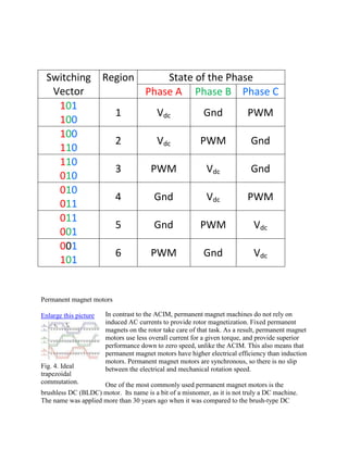
  • 1. SwitchingVectorRegionState of the PhasePhase APhase BPhase C1011001VdcGndPWM1001102VdcPWMGnd1100103PWMVdcGnd0100114GndVdcPWM0110015GndPWMVdc0011016PWMGndVdc<br />Permanent magnet motors <br />Enlarge this pictureleft000Fig. 4. Ideal trapezoidal commutation.<br />In contrast to the ACIM, permanent magnet machines do not rely on induced AC currents to provide rotor magnetization. Fixed permanent magnets on the rotor take care of that task. As a result, permanent magnet motors use less overall current for a given torque, and provide superior performance down to zero speed, unlike the ACIM. This also means that permanent magnet motors have higher electrical efficiency than induction motors. Permanent magnet motors are synchronous, so there is no slip between the electrical and mechanical rotation speed. One of the most commonly used permanent magnet motors is the brushless DC (BLDC) motor.  Its name is a bit of a misnomer, as it is not truly a DC machine. The name was applied more than 30 years ago when it was compared to the brush-type DC motor for its similar speed-torque characteristic. At issue was mechanical commutation (brushes and commutator) versus electrical commutation. So the BLDC motor behaves like a DC (brush) motor as opposed to an AC (induction) motor, but the applied winding voltages are really AC for both. <br />Trapezoidal vs. sinusoidal commutation <br />Enlarge this pictureright000Fig. 5. Sinusoidal commutation.<br />Both trapezoidal six-step (BLDC) and sinusoidally commutated motors (permanent magnet AC or PMAC) most commonly have three stator windings arranged in a 3-wire WYE configuration as shown in Fig. 3. Both motor types are also driven from the same 3-phase Voltage-Source Inverter (VSI) topology also shown in Fig. 3. Phase-currents for both types of motors are controlled by pulse-width modulation of the applied voltage on each phase. Both BLDC and PMAC motors clearly have a lot in common. A casual observer might not even see any difference in the overall construction of these two types of motors. The difference is in the “torque function” of each motor type, and how current is driven into the windings. If each motor type is spun, and the resulting back EMF examined on an oscilloscope, it would be seen that the BLDC motor has a flat-topped trapezoidal voltage, and the PMAC motor has a sinusoidal shape. In order to derive smooth torque from these motors, the applied current should be the same shape as the back EMF. In the case of the BLDC motor, current is applied to only two of the three windings at a time.  During one commutation interval, a steady current is injected into one motor lead, returning through a second lead – and the third lead is open. (It can be used for position estimate by measuring zero-cross). As the motor shaft rotates, the next set of windings is energized, sequencing through all six possible combinations (thus the name six-step) – at which point the motor has gone through one electrical revolution (fractional mechanical revolution depending on how many winding “poles” the motor has). An important implication of this commutation method is that only two of the six inverter switches are conducting at any time, and only two of the three windings carry current at any time. These two factors affect distribution of thermal loads in both the inverter and the motor. Trapezoidal commutation is depicted in Fig. 4. In contrast, for a sinusoidally commutated PMAC motor, each of the three phases of the inverter is modulating (PWM) all the time, driving three out-of-phase sinusoidal currents into each winding. Sinusoidal commutation is depicted in Fig. 5. From an application standpoint, the biggest difference between trapezoidal and sinusoidal commutation is that sinusoidal commutation delivers absolutely smooth torque at any rotational angle or speed. Torque disturbances due to commutation, combined with magnetostriction in the stator generate acoustical commutation noise in BLDC motors. This effect is absent in sinusoidally commutated PMAC motors, making them virtually silent (except for possible PWM noise). Quiet operation is often a very important consideration for appliances. <br />Controlling synchronous motors <br />Enlarge this pictureleft000Fig. 6. Sensorless PMAC controller.<br />Based on the previous paragraph, it may seem that sinusoidal commutation would always be the preferred choice because of the smooth torque and lack of commutation noise. However, there is an additional control burden to consider as well. Simply put, trapezoidal control is simpler to implement than sinusoidal control. This added complexity must be considered in the decision of which motor and control type is best for an application. For BLDC motors, a straightforward PWM current loop can control winding current, while commutation is handled by position sensors (Hall-effect or shaft encoder) or position estimate from winding voltage (from zero-crossing of unused winding). The current loop (which equals torque loop) is then controlled by a velocity control loop, and even an outer position control loop. Top speed of BLDC motor drive is reached when the motor back-EMF reaches the drive bus voltage. At that operating point, the drive cannot deliver enough current to increase motor speed, even at 100 percent duty-cycle. Sinusoidal commutation offers some additional benefits. Simple open-loop variable-frequency sinusoidal drive control is used for ACIM, but not for permanent magnet synchronous motors.  PMAC motors are driven with closed-loop sinusoidal current control. Maximum performance and efficiency is obtained with field-oriented control. Field orientation requires rotor position information, either through direct measurement (encoder) or estimation (sensorless). Motor currents are modeled in a two-axis format with orthogonal direct (D) and quadrature (Q) axis components. The D-axis vector controls the magnetization of the motor, independently of the Q-axis (torque-producing) vector. In normal operation of a PMAC motor, the D-axis command is zero, since the permanent magnets provide the necessary flux-levels. The Q-axis current is then the controlled parameter used to close the torque-loop. For extended speed-range of a PMAC motor, the D-axis command can be set to reduce the motor flux (essentially opposing the flux generated by the permanent magnets). Reduced flux results in a reduced motor constant (both the speed constant Ke, and the torque constant Kt). So the net effect is to enable a higher motor top-speed from the same bus voltage. This method, known as Field Weakening, can practically extend the motor top speed to 3 times higher than without field weakening – at the direct expense of torque. In other words, more speed but lower torque – just like a mechanical gear-ratio. Field weakening can be particularly useful in a clothes washer drive for example: high torque at low-speed is needed for the washing cycle, but high-speed at low torque is needed for best water extraction during the spin-cycle. An example of a complete sensorless PMAC motor drive control system is shown in Fig. 6. This controller uses motor current and voltage feedback to accurately estimate rotor position, eliminating the need for any expensive position sensors or shaft encoders. This complete control system is implemented as a dedicated hardware engine using a low-cost digital process.   For more information, email: epersso1@irf.comAcknowledgements: The author wishes to thank Nicholas Nagel at Illinois Institute of Technology for providing some of the figures. <br />can anyone tell me the difference between sinusoidal- and trapezoidal back EMF? What are the mechanical difference?thanks, Andy sreid (Electrical) 27 May 04 11:53 Brushless motors with sine BEMF are for amplifiers with sine drive currents.  Motors with Trap BEMF are for amplifiers that six step commutate the motor.  The different waveforms are created by the magnet shape and the winding distribution.  The reason for the different BEMF shapes is to minimize torque ripple depending on the drive current waveform shape.Trap waveforms are common in cost sensitive applications (variable speed pump and fan drives). Most high performance servo motors are designed for sine BEMF but they can be driven with six step drives.  This creates additional torqe ripple but it is usually unimporrtant in the application. 字<br />Comparison of sinusoidal excitation and trapezoidal excitation of a brushless permanent magnet motor<br />Top of Form<br />Content is outside your subscription<br />Sign In:Full text access is unavailable with your individual subscription. If your institution subscribes to IEEE Xplore, access may be available by signing in with your institutional credentials. Contact your librarian or informational professional for more details.<br />Forgot Username/Password?Athens/Shibboleth Sign In<br />Bottom of Form<br />Liu, G.;   Dunford, W.G.;   British Columbia Univ., Vancouver, BC  <br />This paper appears in: Power Electronics and Variable-Speed Drives, 1991., Fourth International Conference on Issue Date: 17-19 Jul 1990 On page(s): 446 - 450 Meeting Date: 17 Jul 1990 - 19 Jul 1990 Location: London , UK References Cited: 7 INSPEC Accession Number: 3754297 Date of Current Version: 06 August 2002 <br />Abstract<br />The authors compare the performance of a sinusoidal-type, three-phase, twelve-pole, surface magnet motor using sinusoidal excitation and the performance of the same motor using trapezoidal excitation. The comparison is focused on the overall efficiency of the drive for each method. For sinusoidal excitation, the inverter is modulated by a PWM control signal generated by a Motorola 68HC11 microcontroller. A look-up table is used in the generation of the PWM signal. For trapezoidal excitation, the bottom three MOSFETs of the inverter are modulated by a PWM signal generated by hardware<br />串3<br />