Synthesis of nanoparticles and nanofibers of polyaniline by potentiodynamic electrochemical polymerization
•
3 likes•494 views


Recommended
Recommended
More Related Content
What's hot
What's hot (15)
Viewers also liked
Viewers also liked (18)
Similar to Synthesis of nanoparticles and nanofibers of polyaniline by potentiodynamic electrochemical polymerization
Similar to Synthesis of nanoparticles and nanofibers of polyaniline by potentiodynamic electrochemical polymerization (20)
More from Grupo de Pesquisa em Nanoneurobiofisica
More from Grupo de Pesquisa em Nanoneurobiofisica (20)
Synthesis of nanoparticles and nanofibers of polyaniline by potentiodynamic electrochemical polymerization
- 1. RESEARCHARTICLE Copyright © 2009 American Scientific Publishers All rights reserved Printed in the United States of America Journal of Nanoscience and Nanotechnology Vol.9, 2169-2172, 2009 Synthesis of Nanoparticles and Nanofibers of Polyaniline by Potentiodynamic Electrochemical Polymerization Miguel G. Xavier1 4 , Everaldo C. Venancio1 2 3 ∗ , Ernesto C. Pereira4 , Fabio L. Leite1 , Edson R. Leite4 , Alan G. MacDiarmid2 † , and L. H. C. Mattoso1 1 Alan G. MacDiarmid Institute for Innovation and Business and National Nanotechnology Laboratory for Agribusiness (LNNA), Embrapa Agricultural Instrumentation, C.P. 741, 13560-970, São Carlos-SP, Brazil 2 Department of Chemistry, University of Pennsylvania, 231 South 34th Street, 19104, Philadelphia-PA, USA 3 Centro de Ciências Naturais e Humanas (CCNH), Universidade Federal do ABC, Rua Santa Adélia, 166, Bairro Bangu, 09210-170, Santo André-SP, Brazil 4 Departamento de Química, Universidade Federal de São Carlos, C.P. 676, 13560-905, São Carlos-SP, Brazil Potentiodynamic electrochemical synthesis was used to controllably synthesize nanofibers (mean diameter 48 nm) and/or nanoparticles (mean diameter 88 nm) of polyaniline (PANI) on gold elec- trodes. The films were characterized by cyclic voltammetry (CV), field emission gun scanning elec- tron microscopy (FEG-SEM) and atomic force microscopy (AFM). The type and dimensions of the nanostructures depend on deposition conditions such as monomer concentration and scan rate. This study shows that the nucleation and growth steps play a key role on the film development and its nano-morphology. Keywords: Polyaniline, Nanofibers, Nanoparticles, Electrochemical Polymerization, Nanostructures, AFM, SEM. Polyaniline (PANI) is a promising conducting polymer due to its unique physical and chemical properties which can be used to prepare nanostructures.1–5 One important feature of these materials is the great dependence of the polymer morphology, structure and chain size on the syn- thesis conditions. Chemical polymerization of aniline is the most usual method to prepare PANI. In the litera- ture there are many routes proposed to obtain different morphologies of PANI such as nanotubes6–9 and hollow microspheres8 through self-assembly method,8–9 ultrasonic irradiation7 or by changing the molar ratio of the dopant to monomer.8 Nano and micro spheres were prepared by aqueous oxidative polymerization of aniline in dif- ferent solution pH 10 or by changing the hydrophobic- ity of the substrate where the polymer was deposited.11 Nanoparticles can be obtained changing the solution stir- ring speed which affects the nucleation12 and also by the presence of amphiphilic triblock copolymer micelles.13 Kaner et al. described the change of nanofibrilar morpho- logy of PANI exposing the material to light which gen- erates heat through non-radioactive energy dissipation and exothermic photochemical reactions.14–15 Another way to ∗ Author to whom correspondence should be addressed. † In Memoriam produce, nanocomposites of PANI which has been inves- tigated is by using carbon nanotubes.16–17 A promising approach to obtain PANI nanostructures, which were less explored in the literature, is the use of electrochemical procedures. Potentiodynamic electrochem- ical synthesis is the most used electrochemical technique which allows the control of several parameters such as final electrode potential, number of cycles and scan rate, which might be important to determine the structure of the polymer produced. In addition, different types of solvents and electrolytes, i.e., dopants, which can play an impor- tant role on the definition of polymer morphology, can be also used. The nanostructures which can be obtained there- from may open new possibilities for the preparation of sensors for different liquid analytes (electronic tongue)18–19 or gases.20–21 Considering that small number of studies exploring the formation of nanostructures based on conventional electro- chemical synthesis,22–24 in this work we investigated the electrochemical synthesis of PANI nanoparticles and nano- fibers using CV, studying the effect of monomer concen- tration, scan rate and the potential window on the PANI morphology. The electropolymerization of aniline was carried out in the presence of 1.0 mol L−1 HCl aqueous solution. J. Nanosci. Nanotechnol. 2009, Vol. 9, No. 3 1533-4880/2008/8/001/004 http://dx.doi.org/10.1166/jnn.2009.409 1
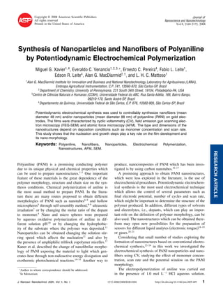
- 2. RESEARCHARTICLE Synthesis of Nanoparticles and Nanofibers of Polyaniline by Potentiodynamic Electrochemical Polymerization Xavier et al. A conventional three-electrode electrochemical glass cell consisting of a platinum foil (counter electrode), saturated calomel electrode (SCE, reference electrode) and a gold electrode (working electrode) was used for the potentiody- namic electrochemical synthesis. The syntheses were per- formed using a potentiostat/galvanostat Autolab PGSTAT 30 instrument. A potential window from −0.2 V to 1.0 V, scan rate of 30 mV s−1 or 50 mV s−1 and the aniline con- centration from 0.02 mol L−1 to 0.5 mol L−1 were used as described in the results and discussion section. The PANI films obtained were rinsed with 1.0 mol L−1 HCl aque- ous solution and then characterized electrochemically in 1.0 mol L−1 HCl aqueous solution. All the experiments were performed at 25 C. The PANI nanostructures were evaluated using FEG-SEM ZEISS model SUPRA 35 and a Discoverer model TMX 2010 AFM instrument in contact mode, including special cantilevers of Si3N4 (0.09 N m−1 ) tips. The AFM images were analyzed using WSxM (Nanotec Electronica S.L.) software.25 The average diameter of the nanoparticles and nanofibers were analyzed using the free software ImageJ 1.37 v.26 Figures 1 and 2 present the polymerization of PANI prepared using different experimental conditions and the respective MEV and AFM images. In the potentiody- namic electrochemical synthesis presented in Figures 1(a) and 2(a), the current peak intensities increase with the number of cycles, indicating a regular growth of PANI nanostructures. There are two redox current peaks in Figure 1(a), peaks A and B. In both Figures 1(a) and 2(a), the current peak A slightly shifts to more positive poten- tials as the growth proceeds, which is probably related to the thickening of PANI films during its polymeriza- tion. In the literature, this peak potential is proposed to be related to the radical cation generated upon oxidation (polaron state).27–28 The current peak A∗ is broader and more negative compared with current peak A, as expected. Current peak B shifts to lower potential, which means that an autocatalytic polymerization occurs during electrolysis of aniline and diradical cations may be generated, which are attributed to further oxidation of PANI to its quinoid form (bipolaron state).29 In Figure 2(a) there are 4 redox processes, i.e., redox pairs M/M∗ , peak G, and H/H∗ , beside the peaks A/A∗ . The main difference in the experimental conditions com- paring Figures 1(a) and 2(a), is the low monomer concentration and the displacement of the final potential towards more positive values. A more detailed explana- tion for the changes in the synthesis voltammograms are beyond the objectives of the present work, but most impor- tantly there are significant changes in the polymer mor- phologies at the nanometer scale, as it will be shown. The results presented in Figure 2(a) indicates that the gold electrode surface was not completely coated with nanopar- ticles of polyaniline, as it can be seen from the current (a) (b) (c) Fig. 1. (a) Cyclic voltammogram of the aniline polymerization in the presence of 1.0 mol L−1 HCl aqueous solution containing 0.5 mol L−1 aniline under electrical potential interval of −0.2 V to 1.0 V (8 cycles and scan rate at 50 mV s−1 ); (b) SEM image of PANI nanofibers elec- tropolymerized (cyclic voltammetry) in the presence of 1.0 mol L−1 HCl aqueous solution containing 0.5 mol L−1 aniline under potential interval of −0.2 V to 1.0 V (8 cycles and scan rate at 50 mV s−1 ); (c) 3D AFM images of PANI nanofibers synthesized as described in Figure 1(a). Scan range of 1 5×1 5 m. peaks H/H*, which could be related to the gold oxide for- mation on the exposed gold surface. The current peak G is related to the monomer electro-oxidation. Concerning the current peaks M/M∗ , some authors30 have attributed them to the presence of a polymer containing phenazine rings, while others28 proposed the oxidation and reduction 2 J. Nanosci. Nanotechnol. 9, 2169-2172, 2009
- 3. RESEARCHARTICLE Xavier et al. Synthesis of Nanoparticles and Nanofibers of Polyaniline by Potentiodynamic Electrochemical Polymerization (a) (b) (c) Fig. 2. (a) Cyclic voltammogram of the aniline polymerization in the presence of 1.0 mol L−1 HCl aqueous solution containing 0.02 mol L−1 aniline under electrical potential interval of −0.2 V to 1.0 V (first cycle, scan rate at 30 mV s−1 ) and −0.2 V to 0.9 V (the following cycles, scan rate at 50 mV s−1 ); (b) SEM image of PANI nanoparticles elec- tropolymerized (cyclic voltammetry) in the presence of 1.0 mol L−1 HCl aqueous solution containing 0.02 mol L−1 aniline under potential interval of −0.2 V to 1.0 V (first cycle, scan rate at 30 mV s−1 ) and −0.2 V to 0.9 V (the following cycles, scan rate at 50 mV s−1 ); (c) 3D AFM images of PANI nanoparticles synthesized as described in Figure 2(a). Scan range of 1 5×1 5 m. of degradation by products. Despite this controversy, it is well known31–33 that changes on the electropolymerization conditions leads to changes in the initial nucleation and growth steps of PANI, which we believe might be dictat- ing the type and size of the nanostructure that is being formed. The electropolymerization condition involves several different variables, such as potential window, scan rate, substrate, electrolyte, ionic strength and aniline concen- tration. Our experimental results indicate that the concen- tration of aniline plays a key role in the formation of either nanofibers or nanoparticles, with higher concentra- tions of aniline (0.5 mol L−1 ) promoting a greater the yield of nanofibers as compared to lower (0.02 mol L−1 ani- line) where basically only nanoparticles can be obtained, under the conditions investigated. Using the SEM images (Figs. 1(b) and 2(b)) and 3D AFM images important insights from morphology polymer growth can be inferred. Figure 1(b) shows PANI nanofibers with average diameter of 48.2 nm. Figure 2(b) shows PANI nanoparticles with average size of 87.7 nm. Figure 1(c) shows bundles of PANI nanofibers. Surprisingly, these AFM images show that, for the first time, the nanofibers are composed of coa- lescent nanoparticles once the fiber radius has an oscilla- tory behaviour in the length direction. Figure 2(c) suggests that the nanoparticles agglomerate into interconnected net- works until they form branched network-like nanofibers. Besides, Figure 2(c), which is the image of the same sam- ple of Figure 2(b), shows a high density region of the nanoparticles which seems to start such process. Mandic27 proposed that such structures growth in two steps: nucle- ation onto bare electrode (step 1) followed by the PANI growth on the already deposited PANI modified surface (step 2). Nanoparticles (mean diameter 88 nm) and nanofibers (mean diameter 48 nm) of polyaniline can be synthe- sized by electrodeposition using a potentiodynamic elec- trochemical method. The type, amount and dimensions of the nanostructures produced depend strongly on the elec- tropolymerization conditions such as monomer concentra- tion, scan rate and the electrical potential interval used. The nucleation process and the growth kinetics are cru- cial in defining the morphology of the nanostrucutures obtained. In addition, AFM studies suggest that nanofibers of PANI seem to be formed by joined nanoparticles. Acknowledgments: The financial support given by LABEX-Embrapa, CNPq, FINEP and FAPESP are grate- fully acknowledged. This paper is in honor of Professor Alan G. MacDiarmid. It is also the first paper published by the Alan G. MacDiarmid Institute for Innovation and Business located at the LNNA, Embrapa/CNPDIA, São Carlos-SP, Brazil. References and Notes 1. C. E. Borato, F. L. Leite, L. H. C. Mattoso, R. C. Goy, S. P. Campana, C. L. de Vasconcelos, C. G. D. T. Neto, M. R. Pereira, J. L. C. Fonseca, and O. N. Oliveira, IEEE Trans. Diel. Elec. Ins. 13, 1101 (2006). 2. F. L. Leite, L. G. Paterno, C. E. Borato, P. S. P. Herrmann, O. N. Oliveira, and L. H. C. Mattoso, Polymer 46, 12503 (2005). J. Nanosci. Nanotechnol. 9, 2169-2172, 2009 3
- 4. RESEARCHARTICLE Synthesis of Nanoparticles and Nanofibers of Polyaniline by Potentiodynamic Electrochemical Polymerization Xavier et al. 3. E. C. Venancio, L. G. Paterno, N. Consolin, C. E. Borato, A. Firmino, and L. H. C. Mattoso, J. Braz. Chem. Soc. 16, 558 (2005). 4. L. G. Paterno and L. H. C. Mattoso, J. Appl. Pol. Sci. 83, 1309 (2002). 5. L. G. Paterno and L. H. C. Mattoso, Polymer 42, 5239 (2001). 6. J. Stejskal, I. Sapurina, M. Trchova, E. N. Konyushenko, and P. Holler, Polymer 47, 8253 (2006). 7. X. Lu, H. Mao, D. Chao, W. Zhang, and Y. Wei, Macromol. Chem. Phys. 207, 2142 (2006). 8. L. Zhang and M. Wan, Adv. Funct. Mater. 13, 815 (2003). 9. Z. Zhang, Z. Wei, and M. Wan, Macromolecules 35, 5937 (2002). 10. E. C. Venancio, P. C. Wang, and A. G. MacDiarmid, Synth. Met. 156, 357 (2006). 11. H. J. Ding, C. J. Zhu, Z. M. Zhou, M. Wan, and Y. Wei, Macromol. Rapid. Comm. 27, 1029 (2006). 12. D. Li and R. B. Kaner, J. Am. Chem. Soc. 128, 968 (2006). 13. D. Cheng, S. C. Ng, and H. S. O. Chan, Thin Solid Films 477, 19 (2005). 14. J. Huang and R. B. Kaner, Chem. Commun. 367 (2006). 15. J. Huang and R. B. Kaner, Nat. Mat. 3, 783 (2004). 16. B. Philip, J. Xie, J. K. Abraham, and V. K. Varadan, Pol. Bull. 53, 127 (2005). 17. G. M. Nascimento, P. Corio, R. W. Novickis, M. L. A. Temperini, and M. S. Dresselhaus, J. Pol. Sci. A Pol. Chem. 43, 815 (2005). 18. F. R. Simões, L. H. C. Mattoso, and C. M. P. Vaz, Sens. Lett. 4, 319 (2006). 19. A. R. Júnior, A. M. G. Soto, S. V. Mello, S. Boné, D. M. Taylor, and L. H. C. Mattoso, Synth. Met. 132, 109 (2003). 20. S. Virji, R. B. Kaner, and B. H. Weiller, J. Phys. Chem. B 110, 22266 (2006). 21. S. Virji, J. Huang, R. B. Kaner, and B. H. Weiller, Nano Lett. 4, 491 (2004). 22. A. J. Motheo, J. R. Santos, E. C. Venancio, and L. H. C. Mattoso, Polymer 39, 6977 (1998). 23. M. Szklarczyk, E. Wierzbinski, K. Bienkowski, and M. Strawski, Electrochim. Acta 51, 1036 (2005). 24. V. Gupta and N. Miura, Electrochem. Comm. 7, 995 (2005). 25. I. Horcas, R. Fernández, J. M. Gómez-Rodriguez, J. Colchero, J. Gómez-Herrero, and A. M. Baro, Rev. Sci. Instrum. 78, 013705 (2007). 26. http://rsb.info.nih.gov/ij. 27. Z. Mandic, L. Duic, and F. Kovacicek, Electrochim. Acta 42, 1389 (1997). 28. D. E. Stiwell and S.-M. Park, J. Electrochem. Soc. 135, 2254 (1988). 29. S. Mu and J. Kan, Electrochim. Acta 41, 1593 (1996). 30. E. M. Genies, M. Lapkowski, and J. F. Penneau, J. Electroanal. Chem. 249, 97 (1988). 31. S. J. Choi and S.-M. Park, J. Electrochem. Soc. 149, E26 (2002). 32. E. C. Venancio, C. A. R. Costa, S. A. S. Machado, and A. J. Motheo, Electrochem. Comm. 3, 229 (2001). 33. S. Y. Cui and S.-M. Park, Synth. Met. 105, 91 (1999). Received: 17 December 2007. Accepted: 14 March 2008. 4 J. Nanosci. Nanotechnol. 9, 2169–2172, 2009