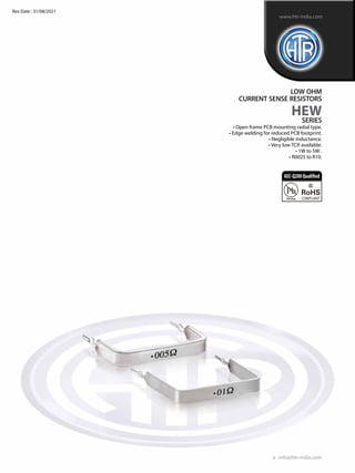
1. • Open frame PCB mounting radial type.
• Edge welding for reduced PCB footprint.
• Negligible inductance.
• Very low TCR available.
• 1W to 5W .
• R0025 to R10.
LOW OHM
CURRENT SENSE RESISTORS
HEW
SERIES
e : info@htr-india.com
www.htr-india.com
Rev Date : 31/08/2021
AEC-Q200Qualified
2. PHYSICAL CONFIGURATION
DIMENSIONAL TABLE
LOW OHM
CURRENT
SENSE
RESISTORS
HEW
ELECTRICAL AND ENVIRONMENTAL CHARACTERISTICS
MECHANICAL SPECIFICATION
Power Rating (Rated Ambient Temperature ) Full power dissipation at 85° C and linearly
derated to zero at + 325 ° C
Insulation Not Insulated
Resistance Tolerance ±10%[K]; ±5%[J]; ±3%[H]; ±2%[G]; ±1%[F]
Operating Temperature Range - 40° C to +125° C with suitable derating as per
derating curve above
Voltage Rating / Limiting Voltage / Max. Working Voltage P x R
Temperature Co-efficient of Resistance TCR as low as ±60ppm/°C to ±500ppm/°C
(Measured from -40°C to +125°C referenced to +25°C) [Depending on resistance value]
Resistance wire/Ribbon TCR ±20ppm [Depending on resistance value]
Damp Heat (Steady State ) ∆R ± < 1% – Average
( 40°C at 93 % R.H. for 1000 Hrs. – no load applied )
Endurance – Load Life [ 70°c with limiting voltage ∆R ± < 1% – Average
– 1.5 hours on / 0.5 hours off for 1000 hours ]
Temperature Cycling ∆R ± < 1% – Average
(-40°C to +125°C for 1000 cycles)
Resistance to Soldering heat - (260°C-270°C for 10 Secs) ∆ R ± [ 0.2 % + R0005 ] – Typical
Solderabillity ( As per IEC pub. 60068-2-20 ) Must meet the requirements laid down
PARAMETER / PERFORMANCE TEST & TEST METHOD PERFORMANCE REQUIREMENTS
PARAMETER / PERFORMANCE TEST & TEST METHOD PERFORMANCE REQUIREMENTS
RESISTANCE
RANGE
DIMENSIONS (mm)
POWER
HTR
Type Rating P H Min. Max. Low Med High
at 85°C (+1.0/-0.5) (Max.)
EW-1 1W 11.43 8.12 R003 R05 0.60 0.30 0.10
EW-3 3W 15.24 23.40 R0025 R10 1.60 1.00 0.40
EW-5 5W 20.32 22.40 R0025 R10 1.75 1.20 0.75
e : info@htr-india.com
www.htr-india.com
TYPICAL WEIGHT PER PC (GMS) BASED
ON RESISTANCE VALUE
MP - Resistance Measuring Point
POWER DERATING CURVE
3.20±0.75mm
H
P
MP
MP
Resistive Element
Tin Plated
Copper/
Tin Plated
Copper Clad
Steel Leads
Weld Point
Ǿ1.70±0.25mm
Ǿ1.0±0.05mm
Rev Date : 31/08/2021
3. TERMINATION
THERMAL DATA
Material : Tin plated copper wire as per ASTM B 189-95 / Tin plated copper clad steel wire as per ASTM B 452-93 (ROHS Compliant / Lead-
free Plating).
Strength : As per spec laid down as per ASTM B 189-95 / ASTM B 452-93.
MARKING
The resistors will be marked as Resistance value followed by tolerance & then symbol“*”for lead free leads & then date code depending
upon space. (Resistance values like R0025/R003/R005 will be marked in milliohms)
e.g EW-1* F R01–Marking will be 01F*datecode & For EW-5*H R005–Marking will be 5H*datecode .
PACKING
FOREW-1=}Whenstripthickness0.40mm500Resistorsshallbepackedinsmallbox“AType”ofapproximatesize200mmX150mmX70mm
for strip thickness 0.40mm, 500 Resistors shall be packed in small box“I Type”of approximate size 70mmx70mmx70mm.
FOREW-3=}Whenstripthickness0.40mm500Resistorsshallbepackedinsmallbox“AType”ofapproximatesize200mmX150mmX70mm
for strip thickness 0.40mm, 250 Resistors shall be packed in small box“I Type”of approximate size 70mmx70mmx70mm.
FOREW-5=}Whenstripthickness0.40mm400Resistorsshallbepackedinsmallbox“AType”ofapproximatesize200mmX150mmX70mm
for strip thickness 0.40mm, 250 Resistors shall be packed in small box“I Type”of approximate size 70mmx70mmx70mm.
The unique construction of HEW series isolates the temperature of the resistance band from PCB material preventing damage to the PCB.
Further, the thermal energy is dissipated to the air rather than being conducted to the PCB where potentially a nearby power component
could be damaged.
The power derating curve provided above is only an approximate indication.
It must be noted that the resistance element of the HEW series is a solid metal alloy band that can tolerate significantly high temperatures
whichcouldbeinexcessof300°C,inviewofthisthedesignengineershouldbasehisselectionontheheatlimitationsofthesolderjoints/PCB.
The charts provided above are merely indicative in nature and the designer must ratify this by actual testing for which samples can be
provided. It is pertinent to point out that the high surge currents shown in the charts are due to the unique construction of HEW series
are far superior in surge applications as compared to any other resistor technology.
PULSE/SURGE CHART (Typically 50 msec duration )
LOW OHM
CURRENT
SENSE
RESISTORS
HEW
e : info@htr-india.com
www.htr-india.com
700
600
500
400
300
200
100
0
1400
1200
1000
800
600
400
200
0
1400
1200
1000
800
600
400
200
0
0 10 20 30 40 50 60 70 80 90 100 0 10 20 30 40 50 60 70 80 90 100 0 5 10 15 20 25 30 35 40 45 50
Resistance (milli-ohms)
EW-1
Resistance (milli-ohms)
EW-3
Resistance (milli-ohms)
EW-5
Surge
Current
(Amps)
Surge
Current
(Amps)
Surge
Current
(Amps)
Rev Date : 31/08/2021
![PHYSICAL CONFIGURATION
DIMENSIONAL TABLE
LOW OHM
CURRENT
SENSE
RESISTORS
HEW
ELECTRICAL AND ENVIRONMENTAL CHARACTERISTICS
MECHANICAL SPECIFICATION
Power Rating (Rated Ambient Temperature ) Full power dissipation at 85° C and linearly
derated to zero at + 325 ° C
Insulation Not Insulated
Resistance Tolerance ±10%[K]; ±5%[J]; ±3%[H]; ±2%[G]; ±1%[F]
Operating Temperature Range - 40° C to +125° C with suitable derating as per
derating curve above
Voltage Rating / Limiting Voltage / Max. Working Voltage P x R
Temperature Co-efficient of Resistance TCR as low as ±60ppm/°C to ±500ppm/°C
(Measured from -40°C to +125°C referenced to +25°C) [Depending on resistance value]
Resistance wire/Ribbon TCR ±20ppm [Depending on resistance value]
Damp Heat (Steady State ) ∆R ± < 1% – Average
( 40°C at 93 % R.H. for 1000 Hrs. – no load applied )
Endurance – Load Life [ 70°c with limiting voltage ∆R ± < 1% – Average
– 1.5 hours on / 0.5 hours off for 1000 hours ]
Temperature Cycling ∆R ± < 1% – Average
(-40°C to +125°C for 1000 cycles)
Resistance to Soldering heat - (260°C-270°C for 10 Secs) ∆ R ± [ 0.2 % + R0005 ] – Typical
Solderabillity ( As per IEC pub. 60068-2-20 ) Must meet the requirements laid down
PARAMETER / PERFORMANCE TEST & TEST METHOD PERFORMANCE REQUIREMENTS
PARAMETER / PERFORMANCE TEST & TEST METHOD PERFORMANCE REQUIREMENTS
RESISTANCE
RANGE
DIMENSIONS (mm)
POWER
HTR
Type Rating P H Min. Max. Low Med High
at 85°C (+1.0/-0.5) (Max.)
EW-1 1W 11.43 8.12 R003 R05 0.60 0.30 0.10
EW-3 3W 15.24 23.40 R0025 R10 1.60 1.00 0.40
EW-5 5W 20.32 22.40 R0025 R10 1.75 1.20 0.75
e : info@htr-india.com
www.htr-india.com
TYPICAL WEIGHT PER PC (GMS) BASED
ON RESISTANCE VALUE
MP - Resistance Measuring Point
POWER DERATING CURVE
3.20±0.75mm
H
P
MP
MP
Resistive Element
Tin Plated
Copper/
Tin Plated
Copper Clad
Steel Leads
Weld Point
Ǿ1.70±0.25mm
Ǿ1.0±0.05mm
Rev Date : 31/08/2021](data:image/gif;base64,R0lGODlhAQABAIAAAAAAAP///yH5BAEAAAAALAAAAAABAAEAAAIBRAA7)