![PHYSICAL CONFIGURATION
HTR TYPE POWER
RATING
at 70°C
RESISTANCE
VALUE
DIMENSIONS (mm)
Power Rating (Rated Ambient Temperature) Full Power dissipation at 70°C and linearly derated
to zero at +275°C - Refer Derating curve above
Operating Temperature Range (Ambient) -55°C to +275°C with suitable derating as per derating curve.
Voltage Rating / Limiting Voltage / Max Working Voltage V= PxR
Maximum Overload Voltage Varies depending on resistance value, duration of overload
and type of pulse waveform. (contact factory for details).
Resistance Tolerances Available J15- C - 5202 para 5.1 ±10% (K); ±5% (J); ±3% (H); ±2%(G); ±1% (F)
ELECTRICAL CHARACTERISTICS / DATA
ELECTRICAL AND ENVIRONMENTAL CHARACTERISTICS
PARAMETER/PERFORMANCE TEST&TEST METHOD PERFORMANCE REQUIREMENTS
W
+ 1
H
+ 1.5
D
+ 1
P
+ 1
WIRE WOUND
RESISTORS
CERAMIC
ENCASED TYPE
HMV
min max
TYPICAL WEIGHT
PER PC (gms)
M2 2.5W 11.0 20.5 7.0 5.0 R04 5K0 3.8
M4 4W 12.0 25.0 7.0 5.0 R04 8K7 5.0
LV5 5W 13.0 25.5 9.0 5.0 R04 13K 6.4
M7 7W 12.5 38.0 9.0 5.0 R05 18K 7.5
LV7 7W 13 (+ 1.5) 38.5 9.0 5.0 R05 22K 10.5
LV10 10W 16.0 35.0 12.0 7.5 R10 26K 15.5
LV10A 10W 13.0 50.0 9.0 5.0 R10 36K 13.0
LV15 15W 20.0 (+ 1.5) 38.0 13.0 7.5 R10 26K 30.0
PARAMETER/ PERFORMANCE TEST TEST METHOD-DETAILS PERFORMANCE REQUIREMENTS
Short Time Overload JIS- C - 5202 para 5.5 Condition B (Voltage ∆R ± [2% + R05]
corresponding to 10 times power for 5 sec)
Dielectric Withstanding JIS- C - 5202 para 5.7 Condition F ∆R ± [1% + R05]
Voltage / Voltage Proof (Limiting voltage x 2 or 1000V)
Temperature Co-efficient of JIS- C - 5202 para 5.2 ± 90 ppm / °C [>10R]
Resistance ± 80 ppm / °C [<10R]
± 200 ppm / °C [<R10]
Insulation Resistance JIS- C - 5202 para 5.6 (Condition F ) >1000MΩ (Min)
Pulse Overload / JIS- C - 5202 para 5.8 (Limiting Voltage x 4) ∆R ± [2%+R05]
Intermittent Overload 1 sec on / 25 secs off 10,000 cycles ± 200 cycles
Endurance - under load JIS- C - 5202 para 7.9 1000 hours at 40°C ± 2°C, ∆R ± [5%+R05] - Typical
with humidity 95% R.H with limiting voltage (1.5 hours on/0.5hours off)
Load Life JIS- C - 5202 para 7.10 1000 hours at ∆R ± [3%+R05] - Average
70°C limiting voltage (1.5 hours on / 0.5 off)
Temperature Cycling JIS- C - 5202 para 7.4 [Room temperature -55°C ∆R ± [2%+R05] - Typical
Room temperature 155°C
Room temperature for 5 cycles.]
Damp Heat (Steady State) JIS- C - 5202 para 7.5 ∆R ± [2%+R05] - Average
Solvent Resistance JIS- C - 5202 para 6.9 Solvent A - IPA for 60secs ±10 secs. No effect on case filling or marking
For LV15 1.0 0.05
e : info@htr-india.com
www.htr-india.com
Rev Date : 14/01/2019](data:image/gif;base64,R0lGODlhAQABAIAAAAAAAP///yH5BAEAAAAALAAAAAABAAEAAAIBRAA7)
Recommended
Recommended
More Related Content
What's hot
What's hot (16)
Similar to WIRE WOUND RESISTORS CERAMIC ENCASED TYPE HMV SERIES SPACE SAVER Slim Type Vertical Mounting
Similar to WIRE WOUND RESISTORS CERAMIC ENCASED TYPE HMV SERIES SPACE SAVER Slim Type Vertical Mounting (20)
Recently uploaded
Recently uploaded (20)
WIRE WOUND RESISTORS CERAMIC ENCASED TYPE HMV SERIES SPACE SAVER Slim Type Vertical Mounting
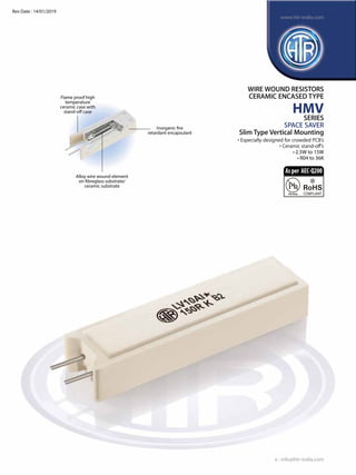
- 1. WIRE WOUND RESISTORS CERAMIC ENCASED TYPE HMV SERIES SPACE SAVER Slim Type Vertical Mounting • Especially designed for crowded PCB’s • Ceramic stand-off’s • 2.5W to 15W • R04 to 36K Alloy wire wound element on fibreglass substrate/ ceramic substrate Inorganic fire retardant encapsulant Flame proof high temperature ceramic case with stand-off case e : info@htr-india.com www.htr-india.com Rev Date : 14/01/2019 Asper AEC-Q200
- 2. PHYSICAL CONFIGURATION HTR TYPE POWER RATING at 70°C RESISTANCE VALUE DIMENSIONS (mm) Power Rating (Rated Ambient Temperature) Full Power dissipation at 70°C and linearly derated to zero at +275°C - Refer Derating curve above Operating Temperature Range (Ambient) -55°C to +275°C with suitable derating as per derating curve. Voltage Rating / Limiting Voltage / Max Working Voltage V= PxR Maximum Overload Voltage Varies depending on resistance value, duration of overload and type of pulse waveform. (contact factory for details). Resistance Tolerances Available J15- C - 5202 para 5.1 ±10% (K); ±5% (J); ±3% (H); ±2%(G); ±1% (F) ELECTRICAL CHARACTERISTICS / DATA ELECTRICAL AND ENVIRONMENTAL CHARACTERISTICS PARAMETER/PERFORMANCE TEST&TEST METHOD PERFORMANCE REQUIREMENTS W + 1 H + 1.5 D + 1 P + 1 WIRE WOUND RESISTORS CERAMIC ENCASED TYPE HMV min max TYPICAL WEIGHT PER PC (gms) M2 2.5W 11.0 20.5 7.0 5.0 R04 5K0 3.8 M4 4W 12.0 25.0 7.0 5.0 R04 8K7 5.0 LV5 5W 13.0 25.5 9.0 5.0 R04 13K 6.4 M7 7W 12.5 38.0 9.0 5.0 R05 18K 7.5 LV7 7W 13 (+ 1.5) 38.5 9.0 5.0 R05 22K 10.5 LV10 10W 16.0 35.0 12.0 7.5 R10 26K 15.5 LV10A 10W 13.0 50.0 9.0 5.0 R10 36K 13.0 LV15 15W 20.0 (+ 1.5) 38.0 13.0 7.5 R10 26K 30.0 PARAMETER/ PERFORMANCE TEST TEST METHOD-DETAILS PERFORMANCE REQUIREMENTS Short Time Overload JIS- C - 5202 para 5.5 Condition B (Voltage ∆R ± [2% + R05] corresponding to 10 times power for 5 sec) Dielectric Withstanding JIS- C - 5202 para 5.7 Condition F ∆R ± [1% + R05] Voltage / Voltage Proof (Limiting voltage x 2 or 1000V) Temperature Co-efficient of JIS- C - 5202 para 5.2 ± 90 ppm / °C [>10R] Resistance ± 80 ppm / °C [<10R] ± 200 ppm / °C [<R10] Insulation Resistance JIS- C - 5202 para 5.6 (Condition F ) >1000MΩ (Min) Pulse Overload / JIS- C - 5202 para 5.8 (Limiting Voltage x 4) ∆R ± [2%+R05] Intermittent Overload 1 sec on / 25 secs off 10,000 cycles ± 200 cycles Endurance - under load JIS- C - 5202 para 7.9 1000 hours at 40°C ± 2°C, ∆R ± [5%+R05] - Typical with humidity 95% R.H with limiting voltage (1.5 hours on/0.5hours off) Load Life JIS- C - 5202 para 7.10 1000 hours at ∆R ± [3%+R05] - Average 70°C limiting voltage (1.5 hours on / 0.5 off) Temperature Cycling JIS- C - 5202 para 7.4 [Room temperature -55°C ∆R ± [2%+R05] - Typical Room temperature 155°C Room temperature for 5 cycles.] Damp Heat (Steady State) JIS- C - 5202 para 7.5 ∆R ± [2%+R05] - Average Solvent Resistance JIS- C - 5202 para 6.9 Solvent A - IPA for 60secs ±10 secs. No effect on case filling or marking For LV15 1.0 0.05 e : info@htr-india.com www.htr-india.com Rev Date : 14/01/2019
- 3. MECHANICAL SPECIFICATIONS Pull Test / Robustness of Terminations Direct load for 15 secs 2 to 4.5 kgs No effect Solderability JIS- C - 5202 para 6.5 ∆R ± [1%+R05] - Typical Continuous and satisfactory (95% Min coverage) PARAMETER/ PERFORMANCE TEST TEST METHOD- DETAILS PERFORMANCE REQUIREMENTS WIRE WOUND RESISTORS CERAMIC ENCASED TYPE HMV TEMPERATURE RISE (AT FULL POWER) (Ambient Temperature 32°C) TYPICAL APPLICATIONS • The HMV series originated in the Far East to provide low cost high power resistors, which could be vertically mounted firmly on to a PCB with stability provided by its ceramic legs. • These resistors find wide application in colour TV’s, VCR’s, Printers, Fax Machines, Inverters and Power supplies. • Due to the nature of their construction, they can withstand surges quite efficiently. Please refer to“ Pulse / Surge capability of resistors”. • For certain applications, these resistors can be supplied fitted with thermal fuse. (please contact factory for details). 1. For RoHS version - M-7 * 2. For Pulse Type - M-7 I 3. For Non Inductive Type - N M-7 4. For 1.0mm lead wire - LV-10 (1) • The graph provided is general in nature and reflects temperature rise of some selected resistance values and is provided solely for the general guidance of the design engineer. • Temperature at Solder Joint on PCB would be substantially lower (please consult factory for details) Note : 1. Type LV10 & LV10A can be provided with 1.0mm leads if required, please specify at the time of placing of the order. 2. The ceramic cases used may be steatite ceramic or corderite ceramic or high alumina ceramic. Thus, the ceramic cases may be off-white or variations of brown / grey, colours which are inherent to these ceramic material. 3. Non inductive type available upto 1K0. ORDERING INFORMATION Series Type Packing Resistance Value Tolerance HMV LV5/LV5* Bulk LV5/LV5* 100R J e : info@htr-india.com www.htr-india.com Rev Date : 14/01/2019