1. 1 | P a g e
CHAPTER ONE
1.1. Introduction
Now a days it is hard to imagine any industry or business that has not benefited from computer
based information system and computer application. Many businesses consider management of their
information resource to have equal importance as managing their key resource .One of those which we
are currently dealing with managing Mega Bookstore information system in Debre Brhan city branch.
Some of the significant of computer based information system for a Bookstore include storing vast
amount of data and inventory control, facilitates user’s record management, and helps to easily identify
the location of materials. It gives timely information about users and store resource, and most important
of all, it increases users’ satisfaction through increased efficiency.
1.2. Back ground
Mega Book store was established by the association which was passed by the association
members and it was started by the year 1982E.c during the Dergue regiem. This the Mega Book store in
Debre Birhan city and other branches were build to develop the capacity to perform tasks so due to
ensure the country ongoing development at the maximum speed .Moreover, so as to solve in ability to
implement tasks ,it is obligatory to develop an electronic system in large quantity as well as quality.
As far as Book store service was concerned, with customers were using in one of the rooms
which was given to the Bookstore by the association member .There were more than 531 books which
are local and foreign published books.
1.3. Statement of the problem
The overall activities of the Bookstore are under taken manually. There repetitive and
cumbersome activities like registering users, reservation, updating records periodically and generating
reports. Due to these the store is facing a lot of problems that need much improvement in order to assist
in realizing organizational objectives.
1.3.1 Registration related problems
Registering users and newly acquired information source is manual and not well organized. This
in turn will result in poor techniques handling in formation related data.
2. 2 | P a g e
1.3.2 Service related problems
The manual storing system used for the purpose of the displaying information about the store and
collection of books, and modification of data requires rework in finding the book .This is a time
consuming and what the user he/she wants, which is tedious.
1.3.3 Reservation
It is not easy to handle reservation, because the Book store is forced to check the entire shelves
which are arranged alphabetically the user’s name. In addition the current system does not allow speed
processing of users request adjustment and cancellation of what has been reserved.
1.3.4. Generating report
Summarizing the different records to generate a report from manual system requires much effort and
it is time consuming and at time it is hardly possible to process make new queries.
1.3.5. Storage
Since all records kept physically on shelves and file cabinets the Book store record keeping system
is poor and subjects to number of problem.
1.4 Objectives of the project
1.4.1 General objectives
The general objective of the project is to change the existing manual system and producing an
automated or electronic (online) product dissemination system throughout the world for the given
organization the book store especially for its primary product the book.
1. 4.2 Specific objectives
The specific objectives of the project are:
Developing user friendly computer based selling of books.
Enable to manage the user’s request in timely manner
Computerized reservation
Enables to generate reports periodically
Helps to store the data in a computerized way.
3. 3 | P a g e
1.5 Significance of the project
Some of the significances of the project are:
o Enables the store customer’s to get fast access and help to the organization in service giving
operations.
o Contributes in realizing organizational goals and objectives by supporting for employees in up
grading and updating their careers, which provides good store service.
1.6 Scopes and Limitation of the Project
1.6.1 Scope of the project
The project that we are trying to focus on Mega book store system will cover only on the Debre
Brhan city branch. The project will cover the following activities:
To register applicant to the system.
Update the system data base.
Cut cost online.
To add book to database.
To search book from database.
To order book.
To generate report periodically.
Limit access level of customers.
1.6.2 Limitation of the project
It would have been of paramount importance if the entire e-shopping for books of the city under
investing action was thoroughly analyzed however ,as it has restriction in relation to time and finance
,this project is limited to e-shopping of the Bookstore and facilitating the system in line with addressing
the problems that are stated understatement of problem area. Our project is also May vulnerable to the
following obstacles.
The project may be difficult to apply at the end i.e. our society is most illiteracy and most live in
rural area.
The project asks high technical support and maintenance.
4. 4 | P a g e
The project does not include the taxation system. Because of the complexity of calculation and
not availability of time.
The payment system concerned/restricted on the commercial bank only and focus on the stored
account value or deposit system i.e. not include the visa card, smart card, ATM card etc because
of security issue.
1.7. Feasibility Study of the New System
The feasibility study is the preliminary study that determines whether a proposed system project is
financially ,technically and operationally viable .the alternative analysis usually include as part of the
feasibility study ,identifies viable alternatives for the system design and development .
1.7.1 Economic feasibility
The project is economically viable since its expected benefits outweigh the expected cost .The project
has a total return on investment of within seven months estimated software life cycle.
Birr cent Birr cent Birr cent in Birr total
1.paper 200 00 200 00 400
2.pen 20 00 20 00 40
3.flesh three 900 00 900
4.CDR-W 40 00 20 00 60
5.CD 30 00 30 00 60
6.laptop one 12500 12500
7.print 200 200
Total 13890 00 270 14160
Table 1 the overall cost of the project
1.7.2 Technical feasibility
We believe that building a working system with acceptable through, response time and other
performance parameter will involve through technical knowledge and technology availability.
5. 5 | P a g e
1.7.3 Operational feasibility
The new system will support the major activities of the store section and will take advantage to
solve the problem out lined in the statement of the problem section .The store head can operate the
system with little training .so we can say that it is operational feasibility.
1.7.4 Schedule feasibility
Realized within the time duration, we have identified the activities in accomplishing the project
objective with their schedule requirement which is on the table below.
Task name Duration Due days
1.project title
submission
Given on3/03/2005E.c 5 days
2.proposal
submission
01/04/2005E.C 1 days
3.requirment
specification
03/04/2005TO20/04/2005E.C 17 days
4.design document 22/04/2005E.CTo12/05/2005E.c 2 0 days
5.implementation
Of the project 05/06/2005To05/10/2005E.C 125 days
6.final project
submission 11/10/2005To15/10/2005E.C 4 days
Table 2 time schedule for the project
6. 6 | P a g e
1.8. Methodology
1.8.1 Fact finding Techniques
The Method and techniques used to analyze the existing system and designing electronic system
includes, interview, document analysis, practical observation. Those methods which help us to gather
the required data to analyze our project and those methods selected due to the time and the
organization’s willingness.
1.8.2 Interview
To get information discussions with the store head will be conducted with concerned staff of the
corporation to get general information.
1.8.3 Document Analysis
This technique provides information on how the existing system works .There for documents related
to the existing system of the organization will be assessed.
1.8.4 Practical observation
It helps us to get real information how the organization performs its function and this helps to
strength the data that gathered through interview and document analysis.
1. 9. System Analysis and Design Techniques
In this project the team will use object oriented system development methodology (OOSD).
This has two phases.
1.9.1 Object Oriented Analysis (OOA):
During this phase the team used to model the function of the system (use case modeling), find and
identify the business objects, organize the objects and identify the relationship between them and finally
model the behavior of the objects.
7. 7 | P a g e
1.9 2. Object Oriented Design (OOD)
During this phase the team uses rational rose software to refine the use case model, and to reflect
the implantation environment, model object interactions and behavior that support the use case scenario,
and finally update object model to reflect the implementation environment.
1.10. Development Environment and programming tools
1.10.1 Back End Design tool
PhpMYADMIN, apache software data base system will be used in developing and managing the
back end.
1.10.2 Front End design tool
The user interface will be developed using HTML integrated development environment since it
easily designing the front end and connected in to data base realizing rapid application development
with constraints on the hand, and we propose to use rational rose soft ware to design different diagrams
like. Use case, class diagram, and activity diagrams etc.
1.11 Team organization
The project team composed of 6 members, one team leader, one deputy leader, one secretary, and
3 members .Problem solving is group activity. Decision on problem and approach are made by group
agreement, which is much better than individual decision.
8. 8 | P a g e
CHAPTER TWO
DESCRIPTION OF THE EXISTING SYSTEM
2. 1 INTRODUCTION
It is necessary to know the existing system of a given organization to develop a better system .The
target area of this project ,Book store e-shopping system currently performs different activities includes
registering new users of the store, reservation, maintain and update records, prepare predict report and
then like. The store is located at distance about 2KM from the Debre Berhan University and to the east-
west direction of the Debre brhan city.
The Book store has more than 600 local users from the city. The store has around 300 copies of
text book periodicals, and CDS published in Ethiopia and abroad. The store focuses mainly on books
with mathematics, health, IT, language, construction engineering, magazines and the like.
2.2. Describing the existing system
The store performs its function with manual system and this leads to less profitable from the
market share .The local books was sold first before the foreign books i.e. Which are imported from the
local products .This is the result of lack of computerized system or web application and the local books
are low in cost than the foreign books.
The store has only one branch in the Debre Brhan city. The books import from the head office of
the association from Addis Ababa as the requirement of the head store requested.
2.3. Player of the existing system
The store creates a job opportunity to the society besides to the service giving to the society. The
main players of the existing system include:
The store head comes with the following responsibilities.
He generates report.
He manages or leads the other employees.
The seller comes with the following activities
He makes speech with the customers.
He accepts the customer’s comment.
9. 9 | P a g e
He checks the reserve books.
The store imports the books primarily from the Mega products, Aster Nega printing enterprise,
selam and Birhan printing enterprises and foreign books but dominantly local products.
As we tried to explain in the proposal part the store runs its function by the local customers
dominantly because of the problems that we specified under the problem area. Some sectors buy
some books to distribute and to apply for some reading to guide to develop the capacity of the
employees.
2.4 Work flows in the existing system
The work flow in the existing system is performed starting from the top store head to lower the
seller person. The books imports from the main office at Addis Ababa monthly or weekly based on
which types of books were sold first these books received by the head store of the branch office.
The store head administered all the books and lead the other employee’s .The seller sell the books
based on their price that is specified on dimension of the books and the accountant gives receipt to the
customers who bought the book that is the seller do two activities at the same time simultaneously. In
the following diagram we will try to put the work flow in the existing system.
Leads to
Checks
Cut cost from
Sells book to
Generat
e report
Store head:
Accountant:Reserve
book
Seller:
The
customer
Customer
or buyer
10. 10 | P a g e
2.5 Report generating in the existing system
The head store generates report weekly and monthly what activities are performed, the report is
manual, it takes time to reach the main office. This report which includes about selling of the books,
about the employees, and about the market requirement of the books, and the total condition of the
environment .This report submits to Addis Ababa to which the head office is located, and the office
sends the response to the branch office which is the sender.
2.6 Business Rules in the Existing System
A business rule is effectively an operating principle or polices that we try to specify for both the
existing system and the new system must satisfy. The business rule is a principle or a policy in which the
proposed system operates accordingly. It deals with access control issues.
It often pertains to access control issues, operating policies and principles of the organization. The
organization has the following principles in the existing system which includes:
The organization does not functional on Sunday. So our project will solve this problem because
this deals with 24 hour per 7 weeks.
It does not reach books to customers to their address.
The organization prepares reports to the higher officials monthly.
The organization is functional only restricted time (from 2:30-5:30 morning and from 7:30-
11:00 afternoon).
The organization does not functional on holiday.
Our proposed system includes the following operating principles or rules:
Business Rule1: the customer uses the application properly.
Business Rule2: the customer fills the form properly.
Business Rule3: the system gives fast responses to the customer.
Business Rule4: the system should work 24 hours and 7 days per a week.
Business rule5: the system helps to arrive the books to the customer place.
Business rule6: it provides more options to customers.
11. 11 | P a g e
2.7. Problems in the existing system
The existing system actually faces to a lot of problems, and these problems results due to the manual
system of accomplishing its operations. Such as:
Reservation
Records about any activity in the store are kept manually. Records about books, user, and senders are
also kept manually on registers and records which are alphabetically arranged in a wooden box. This
may result in the data lost.
Report generation
The store head generates report on weekly or monthly. The store condense general information about
the activates performed within the members. This is difficult to integrate the various information’s to
generate the report.
Storage
Since all records kept physically on shelves and file cabinets the Book store record keeping system
is poor and subjects to number of problem:
There is no means of keeping backup
Space
There is also loose of physical recordings through times
The system is vulnerable to misplacement of the record
Registration related problems
Registering users and newly acquired information source is manual and not well organized .This in
turn will result in poor techniques handling information related. Such as
Difficult to integrate data from different individual records
Unable to entertain different user request.
12. 12 | P a g e
Service related problems
The manual storing system used for the purpose of the displaying information about the store and
collection of books, and modification of data requires rework in finding the book .This is a time
consuming and what the user he/she wants, which is tedious .In the organization there is also a market
related problems, since most of the customers are local because of the system is not web based. Not only
is this but there also a distribution related problem within the existing system.
2.8. Alternative Solution
As we try to describe above the current system faces some problems and the problem’s primarily
resulted from the manual system of running the activities and we try to put an alternative solution to the
problems which are described in the above problem identifying in the existing system section.
The best alternative solution to the existing system is to change the existing manual
system and producing an electronic (online) system for the Bookstore.
2.9 The proposed system
2.9.1. Functional requirement
These requirements which are the basic for the system or simply functional requirements that the
system must satisfy. These groups of requirement stress functionality that the system should support for
the user.
Applicant registration: the system should provide the store standard to register the applicant.
Book registration: The system should support registration of information on recording and
holding of the book store.
It will generate report in easy way.
The system developed to cut cost online from the customer.
The administrator updates the periodical information.
The customer order book online.
The system allow to the customers, shop assistant to search book in a fast mechanism.
13. 13 | P a g e
2.9.2 Non functional requirement
These constraints are the user visible aspect of the system.
Which includes?
User interface: since users of the system involved people with different back ground, the system
should be made with user friendly window type.
Performance and Access time: The system will provide fast access to the customer according to
their privilege.
Security: the system should enable to task a back up at any time in point in point and able to
restore from backups.
14. 14 | P a g e
CHAPTER THREE
ANALYSIS DELIVERABLES OF THE NEW SYSTEM
3.1 Introduction
Model is an abstraction of the real world. It allows us to deal with the complexity current in
a real-world problem by focusing on the essential and interesting features of an application. The
techniques and associated notation used for object oriented analysis and design in incorporated in
to a standard object – oriented language called unify Modeling language (UML). An important goal
of requirement modeling is come to an understanding of the useless problem that the new system
is to address. This chapter focuses on developing the requirement and analysis models for the new
system using the UML use case model, sequence diagram, activity diagram and class diagram and
interface prototyping are also included.
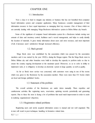
3.2 USE CASE DIAGRAM
A use case is a sequence of action that provides a measurable value to an actor another way
to look at it is that a use case describes a way to which a real world to interacts with the system.
An essential use case sometimes called a business the case is simplified, abstract, generalized use
case that captures the intention of the user in a technology and implementation independent
manner.
The case models are used to document the behavioral (functional) requirement of a system or
the “what “of the system (Scott W. Ambler 2001)
A use case describes a sequence of action that provides a measurable value to an actor and
draw as a horizontal ellipse.
An actor is a person, organization, or external system that plays a role in one or more
interactions with the system and draw as stickman figure.
Relationship between actors and use cases exists whenever an actor is involved with an
interaction described by a use case and modeled as a line connecting use cases and actors.
15. 15 | P a g e
Payment
Search book
login
Updatebook
add book
apply to register
generate reporet
order book
applicant
shopassistant
manager
Customer
Administrator
logout
delete comment
«uses»
«uses»
«uses»
System Usecase
Fig.1 Use Case diagram
16. 16 | P a g e
3.2.1 Actor description
Shop assistant: performs login and search book activities.
Applicant: the applicant performs only applied to be registered.
Manager: performs activities login and generate report.
Customer: performs activities login, search book and order book.
Administrator: performs activities login, add books and update books.
3.2.2 USE CASE TEXTUAL DESCRIPTION
Use case name: Login use case
Identification: UC01
Description: use case to ensure security in system usage
Actor: user: (customer, manager, shop assistant and Administrator.)
Precondition: the user must have username and password.
Post condition: user get access to the system according to their predefined system privilege and
finally he/she logout or turn off the page.
Basic course of action:
1. User activates the system.
2. System response by displaying the login interfaces and prompts the user for the user ID and
password.
3. User fills his or her user ID and password and presses enter.
4. System verifies user ID and Password.
5. User authenticated and gets access to the system.
6. System displays its main window.
7. Use case ends.
Alternative course of action (if user enters wrong user ID and / or password)
A1. User is not authenticated and is denied access to the system.
A2. System displays an incorrect user ID and password message.
A3. System enables user to try again.
A4. Use case returns to step 2 of main use case.
17. 17 | P a g e
Use case name: apply to register
Identification: UCO2
Description: use case to register new applicant.
Actor: applicant
Precondition: the applicant must be able to fill all the criteria perfectly and the applicant has the
ability to access the internet.
Post condition: an applicant or new customer is registered.
Basic course of action
1. Not include login use case.
2. Applicant selects applicant’s link.
3. Applicant select form.
4. System display applicant form.
5. Applicant fills necessary data.
6. Submit.
7. Use case ends.
Alternative course of action (if applicant enters wrong information)
A1. Applicant is not authenticated and is denied access to the system.
A2. System displays an incorrect message.
A3. Use case returns to step 5 of main use case.
Use case name: Search Book
Identifier: UC03
Description: use case to retrieve a book call number to browse store collection.
Actor: customer
Precondition: the customer must be a member must be an employee.
18. 18 | P a g e
Postcondition: System display information about the book its holding.
Basic course of action:
1. Include login use case.
2. Customer activates the book interface.
3. Customer selects brows book from the displayed link.
4. System responds by displaying the browse book interface.
5. Customer selects the search criteria and enters the search key word.
6. System consults the database and displays the collection matching the search key word.
7. Use case ends.
Alternative course of action (user entered a search key word that doesn’t exist in the system)
A1. System responds stating there is no resource matching the search in its result display.
A2.use case returned to step 5.
Use case name: Order Book
Identifier: UC04
Description: use case to order a book to browse from store collection.
Actor: customer
Precondition: the customer must be a member.
Post condition: system displays information about the book its holding.
Basic course of action:
1. Include login use case.
2. Customer activates the order interface.
3. Customer selects brows order from the displayed link.
4. System responds by displaying the browse order interface.
5. Customer selects the order criteria and enters the order key word.
19. 19 | P a g e
6. System consults the database and displays message.
7. Use case ends.
Alternative course of action (user entered an order key word that doesn’t much in the system)
A1. System responds to fill the criteria again message.
A2.use case returned to step 5.
Use case name: update book
Identifier: UCO5
Description: use case to edit or update the existing book information.
Actor: administrator
Precondition: administrator he/she must be an employee and have a certificate in DBMS.
Post condition: system updates the book information.
Basic course of action
1. Start or include login use case.
2. Administrator selects record link.
3. Administrator clicks the search button from displayed record link.
4. Use displays the search form.
5. Administrator enters ISBN on the search forms and click search.
6. System retrieves the book particulars and displays on the maintain book form.
7. Administrator edits the book particulars or information.
8. Administrator clicks save.
9. Use case ends.
Alternative course of action (if administrator enters wrong ISBN)
A1. ISBN is not authenticated and is not exist in the data base.
A2. System displays a book is not exist message.
A3. System enables administrator to try again.
20. 20 | P a g e
A4. Use case returns to step 2 of main use case.
Use case name: add book
Description: UC06
Actor: Administrator
Precondition: Administrator wants to add a book to the data base.
Post condition: system adds the book to the data base.
Basic course of action:
1. Include login use case.
2. Administrator selects record link.
3. Administrator clicks the add button from displayed record link.
4. System displays the search form.
5. Administrator enters ISBN on the add form and click search.
6. System retrieves book particulars or information and displays the maintain book form.
7. Administrator over views the add entry.
8. Administrator clicks the add button.
9. End use case.
Use case name: generate report
Identifier: UC07
Description: use case to generate report.
Actor: manager
Precondition: the manager he/she an employee and have managerial skill about human resource and
should have skill to integrate different information.
Post condition: system displays report.
Basic course of action:
1. Include login use case.
21. 21 | P a g e
2. Manager activities the report interfaces.
3. Manager selects the report category from the displayed report link.
4. Manager selects the report type from the displayed report link.
5. System responds by responding criteria form.
6. Manager set the criteria according to his or her requirement and clicks the display button.
7. System responds by displaying report extracts from the data base.
8. Use case ends.
Use case name: payment
Identifier: UC08
Description: use case to payment.
Actor: customer
Precondition: the customer he/she must have an account in the organization in order to order and
purchase book from the organization.
Post condition: system displays account of a customer.
Basic course of action:
1. Include login use case.
2. Customer activities the payment interfaces.
3. Customer goes to the payment category when he or she fills correctly the order form.
4. Customer selects the payment type from the displayed report link.
5. System responds by responding criteria form.
6. Customer sees the criteria according to his or her requirement.
7. Use case ends.
3.3 Class Diagram
Diagrams are used to represent the structure of the system in terms of objects, their notes and nature
of relationship between classes. It shows the static features of the objects and do not represent any
particular processing.
Have the following classes
22. 22 | P a g e
It is an abstraction of the real environment class of seller, patron (user) and Administrator.
Shop assistant: is the representation of the real world class or seller which interacts with system to
accomplish the seller activity.
Customer: is the representation of the real world user.
Administrator: is an administrator which uses the automated system to retrieve report.
Book: it is the representation of the real world class of books.
Report: a summary of information about the library to deliver to the library administrator.
23. 23 | P a g e
Fig .2 Class Diagram Analyses
3.4 Sequence Diagram
A sequence diagram is a UML interaction diagram. It represents the chronology of the passing of
messages between system objects and actors. It may be used to illustrate a possible scenario of a use
case, the execution of an operation, or simply an interaction scenario between classes of the system.
24. 24 | P a g e
You can use one or more sequence diagrams to pass a use case or to identify all the possibilities of
a complex behavior. A sequence diagrams conveys the same kind of information it concentrates on the
chronology of messages passing between the objects in place of their structure.
A sequence diagram shows actors, objects (instances of classes) and the messages sent between
them. By default, Power Designer provides an "interaction frame", which surrounds the objects in the
diagram. Messages can originate from or be sent to any point on the interaction frame, which acts as the
exterior of the system being modeled, and these gates can be used in place of actor objects.
Fig.3 Login Sequence Diagram (uc01)
Login f orm
User
Main
Window (UI)
Login controller DatabaseLogin link
Login use
Case# 01
Customer
1. Customer activ ates UI.
2. Select the login link.
4. Fill user name and
Password
5. Submit.
Sy stem
3. Display the login f orm.
6. Validate the data
7. Return to step 4. Unless
Follow step 5.
9. Check.
10. Response
1: customer activ ates UI ()
4. Fill user name and password ()
3: Display the login f orm ()
10. Response ()
8. Step 5 continue ()
7. Try again ()
9. Check ()
5. Submit ()
6. Validate ()
2. Select the login link ()
25. 25 | P a g e
Fig. 4 Sequence diagram for register applicant UC#02
: applicant
applicant link applicant form applicant
controller
Databasemain window(UI)
use case
apply to
register#uc2
applicant
1.activate.
2:the applicant
select the
applicant link.
4.fill the form.
5.submit.
system
3.display the
applicant form.
6.validate the
data.
7.if error try again
message display
or step 4
continue.
9:check.
10:se...
4.applicant fill the form()
3.Display the applicant form()
5.submit()
6.validate()
7.return to step 3 ()
8.continue step 4()
9.check()
10.response()
1.activate()
2.select applicant link()
26. 26 | P a g e
Fig.5 sequence diagram for search book UC#3
: Customer
search link search controller databasesearch form
search book
use case#03
customer
1:select applicant
link.
2:select the search
form.
4:customrer fill the
form.
5.submit.
system
3. display search
form.
6. validate the data.
7.try again unless
step four continue.
9. check in
database.
10.response.
1.select applicant link ()
2.display seach form()
3. fill search form()
4. submit()
5. validate()
6.try again()
7.step 4 continue()
8.check()
9.response()
27. 27 | P a g e
Fig.6 sequence diagram for order book#UC04
: Customer
order link order form order controller databaseorder book use
case UC#04
customer
1:select order link.
3:customer fill the
order criteria form.
4:the customer sends
the request.
system
2:display order form.
5.validate the data.
6.return message to
refill or step 4
continue.
8.check.
9:the system sends
the respons.
1:select order link()
3:the customer fill the form()
2.display order form()
4.submit()
5.validate()
6.fill again()
7.step 4 continue()
9.response()
8.check()
28. 28 | P a g e
Fig .7 Update book sequence Diagram (uc05)
: Administrator
update link update book form update controller database
Update book
use case #05
adminstrator
1:select update
link.
3:fill the record.
4:submit the
request.
9:administrator
edit the record
system
2:the system
display update
form.
5.validate.
6.try again
message unless
step 4 will
continue.
8.check.
10.save.
1.select update link()
3.the administrator fill the update form()
2.display update form()
4.submit()
5.validate()
6. try to update again()
7.step 4 will continue ()
8.check()
9.edit()
10.save()
29. 29 | P a g e
Fig .8 Sequence diagram for add book#UC06
: Administrotor
add link add form add controller database
add book
usecase #06
administrator
1:select add link.
3.fill add form.
4.submit.
system
2:the system
display the add
form.
5.validate.
6.try again
message
otherwise step 4
will continue.
8.check.
9.response.
1.select add link()
3.the administrator fill the add form()
2.display add form()
4.submit() 5.validate()
7.step 4 will continue()
6.try again to add()
9.response()
8.check()
30. 30 | P a g e
Fig .9 Sequence diagram for generate report#UC07
manager
1:select report link.
3:the manager fill the
report form.
4:submit .
system
2:the system display's
the report form.
5:validate the data.
6.try again message
otherwise step 4 will
continue.
8:check.
9:response.
: Manager report link report form report controller database
generate
report use
case #7
1.select report link()
3.the manager fill the report form()
2.display report form()
4.submit()
5.validate()
6.try again()
7. step 4 will continue()
9.response()
8.check()
31. 31 | P a g e
Fig .10 Sequence diagram for payment #UC08
: Customer
Payment link Payment form Payment controller DatabasePayment use
Case UC#08
Customer
1: select payment link.
3: customer fill the
Payment criteria form.
4: the customer sends
The request.
System
2: display payment form.
5. Validate the data.
6. Return message to
Refill or step 4
Continue.
8. Check.
9: the systemsends
The response.
1: select payment link ()
3: the customer fills the form()
2. Display payment form()
4. Submit ()
5. Validate ()
6. Fill again ()
7. Step 4 continue ()
9. Response ()
8. Check ()
32. 32 | P a g e
3.5 Activity Diagram
An activity diagram illustrates the dynamic nature of a system by modeling the flow of control
from activity to activity. An activity represents an operation on some class in the system that results in a
change in the state of the system. Typically, activity diagrams are used to model workflow or business
processes and internal operation. Because an activity diagram is a special kind of state chart diagram, it
uses some of the same modeling conventions. Activity diagrams are mainly used as a flow chart consists
of activities performed by the system. But activity diagram are not exactly a flow chart as they have
some additional capabilities. These additional capabilities include branching, parallel flow etc.
Fig.10 Activity diagram for login use case
user
verify login
USERID and
PASSWORD
invalid
Display link
Window
valid
33. 33 | P a g e
Fig.11 Activity Diagram For Apply To Register
Applicant
Fill Applicant
Form
invalid
display
response
valid
send
check
34. 34 | P a g e
Fig.12 Activity Diagram For Search Book
Customer
(Is Found)
fill search
criteria
display result
invalid
valid
35. 35 | P a g e
Fig.13 Activity Diagram For Order Book
Enter Book
particulars
Allow to Select
invalid
valid
Select Action
Customer
Display
Selected Item
is found
36. 36 | P a g e
Fig.14 Activity diagram for update record
Administrator
(is found)
invalid
valid
fill update
criteria
Display Record
edit
save
37. 37 | P a g e
Fig.15 Activity Diagram For Add Book
Administrator
fill add criteria
invalid
display
response
valid
confirm
38. 38 | P a g e
Fig.16 Activity Diagram For Generate Report
Manager
fill report criteria
prepare report
valid
invalid
is found
39. 39 | P a g e
Fig.17 Activity Diagram For payment
3.6 User interface prototype of the new system
User interface (UI) prototyping is an iterative analysis technique in which users are actively
involved in making up of the UI for a system. UI prototypes have several purposes:
As an analysis artifact that enables you to explore the problem space with your stakeholders.
As a requirements artifact to initially invasion the system.
As a design artifact that enables you to explore the solution space of your system.
A vehicle for you to communicate the possible UI design(s) of your system.
Fill the payment
form
check account
confirm order
(enough)
(yes)
enough/low?
(No)
your account balance is low!!
40. 40 | P a g e
A potential foundation from which to continue developing the system (if you intend to throw the
prototype away and start over from scratch then you don’t need to invest the time writing quality
code for your prototype).
Fig.17 System Prototyping
41. 41 | P a g e
CHAPTER FOUR
DESIGN DELIVERABLES OF THE NEW SYSTEM
4.1 Introduction
The purpose of designing is to show the direction how the web page is built and to obtain clear
and enough information needed to drive the actual implementation of web page. It is based on
understanding of the model the web page built on system design also focuses on decomposing the
system in to manageable parts.
During system design we concentrate on the process of data structures and soft ware and hard
ware components necessary to implement it.
4.1.1 Design goals and objectives
The objectives of designing are to model a system with high quality. Implementing of high
quality system depends on the nature of the design created by the designer .If one wants to make
changes to the system after it has been put in to operation depends on the quality of the system design.
So if the system is designed perfectly, it will be easy to make changes to it.
The goal of the system design is to manage complexity by dividing the system in to manageable
pieces.
Some of the goals are listed below.
Security: The system should be secured from unauthorized user.
Modifiability: The system should be modifiability to modify different services depending on the
need of the institute.
Flexibility: The system able to change to suit new condition or situation.
Efficiency: The system must do what it is supposed to do efficiently without the problem.
4.2 Design the class diagram
Diagrams are used to represent the structure of the system in terms of objects, their notes and
nature of relationship between classes. It shows the static features of the actors and do not represent any
particular processing. It is an abstraction of the real environment class of seller, patron (user) and
Administrator.
42. 42 | P a g e
Shop assistant: is the representation of the real world class or Shop assistant who interacts with system
to accomplish the Shop assistant’s activity.
Actor (customer): is the representation of the real world store customer.
Administrator: is an administrator which uses the automated system to retrieve report.
Book: it is the representation of the real world class of books.
Reserve: it is an associate class that contains information about data of reserve with respective book.
Report: a summary of information about the book store to display to the customers.
44. 44 | P a g e
4.3 Collaboration diagram
A collaboration diagram is an illustration of the relationships and interactions among objects in the
unified modeling language.
Fig: 02 Collaboration diagram for login.
: Customer
Login form
User
Interface (UI)
Database
Login
Controller
9: 9.check ()
6: 6.validate ()
1: 1: customer activates UI()
4: 4.fill user name and password ()
3: 3: Displaythe login form ()
5: 5.submit()
2: 2.selectlogin form ()
10: 10.response ()
8: 8.step 4 continues ()7: 7.try again ()
45. 45 | P a g e
Fig: 03 Collaboration diagram for apply to register.
applicant
form
: applicant
applicant
link
applicant
controller
Database
5: 5.validate() 8: 8.check()
1: 1.apllicant select the applicant menu()
2: 2.Display the applicant form()
3: 3.applicant fill the form()
4: 4.submit()
6: 6.return to step 3 ()
7: 7.continue step 4()
9: 9.response()
46. 46 | P a g e
Fig04: Collaboration diagram for search book.
: Customer
Database
Search link
Search
Controller
Search form
5: 5. Validate ()
8: 8.check ()
1: 1.selectapplicantlink ()
4: 4. Submit()
9: 9.response ()
6: 6.try again ()
7: 7.step 4 continues ()
2: 2.displaysearch form ()
3: 3. Fill search form ()
47. 47 | P a g e
Fig05: Collaboration diagram for order book.
Order link Order form
: Customer
Order
Controller
Database
5: 5.validate ()
1: 1: selectorder link()
2: 2.displayorder form ()
3: 3: the customer fills the form ()
4: 4.submit()
6: 6.fill again ()
7: 7.step 4 continues ()
8: 8.response ()
48. 48 | P a g e
Fig06: Collaboration diagram for update book.
: Administrator
update book
form
update link
update
controller
database
5: 5.validate()
8: 8.check()
1: 1.select update link()
2: 2.display update form()
3: 3.the administrator fill the update form()
4: 4.submite()
6: 6. try to update again()
7: 7.step 4 will continue ()
9: 9.edit()
10: 10.save()
49. 49 | P a g e
Fig07: Collaboration diagram for add book.
add form
: Administrotor
add link
add controller database
5: 5.validate()
8: 8.check()
1: 1.select add link()
2: 2.display add form()
3: 3.the administrator fill the add form()
4: 4.submit()
7: 7.step 4 will continue()
6: 6.try again to add()
9: 9.response()
50. 50 | P a g e
Fig08: Collaboration diagram for generate report.
: Manager
Reportform
Reportlink
Report
Controller
Database
5: 5.validate () 8: 8.check ()
1: 1.selectreport link ()
2: 2.displayreport form ()
3: 3.the manager fill the report form ()
4: 4.submit()
6: 6.try again ()
7: 7. Step four will continue ()
9: 9.response ()
51. 51 | P a g e
4.4 State chart diagram
The state chart diagram used to show the sequence of states that an object goes through the events
that cause the transition from one state to the other and the actions that result from a state change.
Fig 09 Login state chart diagram
Fig 10 State chart diagram for applicant register
idle fill the form send
request
final state
verify
confirm
request
Evaluation
activate
un normal exit
normal exitintial state
complete state
leave the page
IdleInitial state LoginActivate Verify loginNormal exit
Confirm
Login
Evaluation
Final state
Un normal exit
Complete state
Fail
52. 52 | P a g e
Fig11: State chart diagram for search book
Fig 12 State chart diagram for order book
idleintial state send search
request
activate verify search
request
normal state
confirm
search
Evaluate
final state
unnormal exit
complete state
book not found
idle send order
request
select
order item
confirm
order
intial state fill request normal exit
Evaluation
final state
un normal exit
complete state
leave ordering
53. 53 | P a g e
Fig13: State chart for update book
Fig13: State chart diagram for report generate
idle send update
request
edit
confirm
update
save
final state
unnormal exit
intial state
fill update request normal exit
Evaluate
complete state
ignor edit
idle
intial state
send report
request
select
reporttype
normal exit
final stae
unnormal exit
confirm
report
display
Evaluation
complete state
fill report form
improper select
54. 54 | P a g e
4.5 Data base design
Database Design is the database structure that will be used as plan to Store and manage the data.
The database management system (DBMS) is the software used to implement a database design.
Modern database and applications development software is so easy to use that many people can quickly
learn to implement a simple database and Develop simple applications within a week or so, without
giving design.
Much thought, As data and reporting requirements become more complex, those same people will
simply and produce the required data by incorrectly adding more columns of tables to the database.
Fig: 14 Organizational Database design (bookstore)
Fig: 15 Bank Database design
55. 55 | P a g e
CHAPTER FIVE
IMPLEMENTATION DELIVERABLE OF THE NEW SYSTEM
5.1 Introduction
Implementation refers to the Coding of the all documents gathered starting from requirement
analysis to Design phase. So now the team is in a position of converting all documents gathered and
designed into the code so that the system will be implemented for the user to be used for the purpose it
developed. To implement it the user must have a server on which the system will be hosted because this
system can run on intranet site with connection available or on internet connection.
5.2 Component diagram
In this Diagram components of the system will be wired showing that there is relation among
components, management of the system, database and operations performed on databases such security
issue. This in some extent shows which component or objects will be accessed by whom and what type
of security infrastructures it is using. The diagram is simulated below.
Fig: 16 Component diagram
56. 56 | P a g e
5.3 Deployment diagram
Deployment modeling is used to show the hardware of the system, the software that is installed in
the hardware and also the middleware that is used to connect the disparate machines to one and other. It
also shows how the software and the hardware components work together.
Fig: 17 Deployment diagram
57. 57 | P a g e
5.5 user interface design
In this system users will communicate with the system through the following user interfaces.
Home Page: This form appears on the site in which the system deployed is opened and contains some links
which lead the user to other page according to his privilege, and if the user is authorized user or has an
account, he/she will directly go to the page that he want by entering correct username ,password and role.
Fig: 18 User interface design for home
58. 58 | P a g e
Fig: 19 User interface design for register applicant
59. 59 | P a g e
Fig: 20 User interface design for comment
60. 60 | P a g e
Fig: 21 User interface design for Login
61. 61 | P a g e
6. Prototype development
Prototype development can be defined it is the sample code of the given project. These are some
of the sample codes that we have done it.
Sample code for Register an applicant
66. 66 | P a g e
CONCLUSION
This is a system development project which two phases; the first phase deals with the analysis
phase of the life cycle, and the next phase addresses the Design phase. As the end of the first phase, we
need to review that we have covered in accordance with what we have planned at the beginning. We
began our work by identifying the significance of automated system for the store and the overall
techniques to be used in the development process. This involved defining the system development
methodology, identifying process. This involved defining the system development methodology,
identifying resource and cost requirements, and setting the deliverable and scheduled for the project.
The business area Analysis helps the team to truly understand the major functional areas and
processes of the system. Through this we evaluate the existing system weakness and strength.
After that, we performed requirements elicitation to discover user and system requirements. This
phase consisted of drawing the functional as well as non-functional requirements of the system. Then we
have undertaken a major phase in system development process: object oriented Analysis. Here, we tried
to model the new system we proposed using UML diagrams: Use case, sequence, and activity and class
diagrams Also, we designed the new system user interface prototype.
67. 67 | P a g e
RECOMMENDATION
The system that we are trying to develop is not a fully electronic shopping system. Because the
cart and tax of the store are not integrated in the system. This is mainly due to limited development
capacity and time.
Therefore, we suggest the following features need to be incorporated in any further revision and
extension attempt.
- Online registration of customer and enable them view the resources of the store and their status
via web page.
- Integration with other section of the store.
- The system should develop the card payment system for the future.
68. 68 | P a g e
REFERENCE
1. Ambler, Scott (2001) The Object primer: The application Developers Guide to Object
Oriented and the UML.2nd rev. Ed England: The Cambridge University Press.
2. Bruegge, Bernd (2000) Object oriented Soft ware Engineering Conquering Complex and
Changing System. Upper Saddle River: Prentic Hall.
3. Chopra, R.N (1999) Dictionary of Library Science. New Delhi Anmol Publication