Download as PDF, PPTX
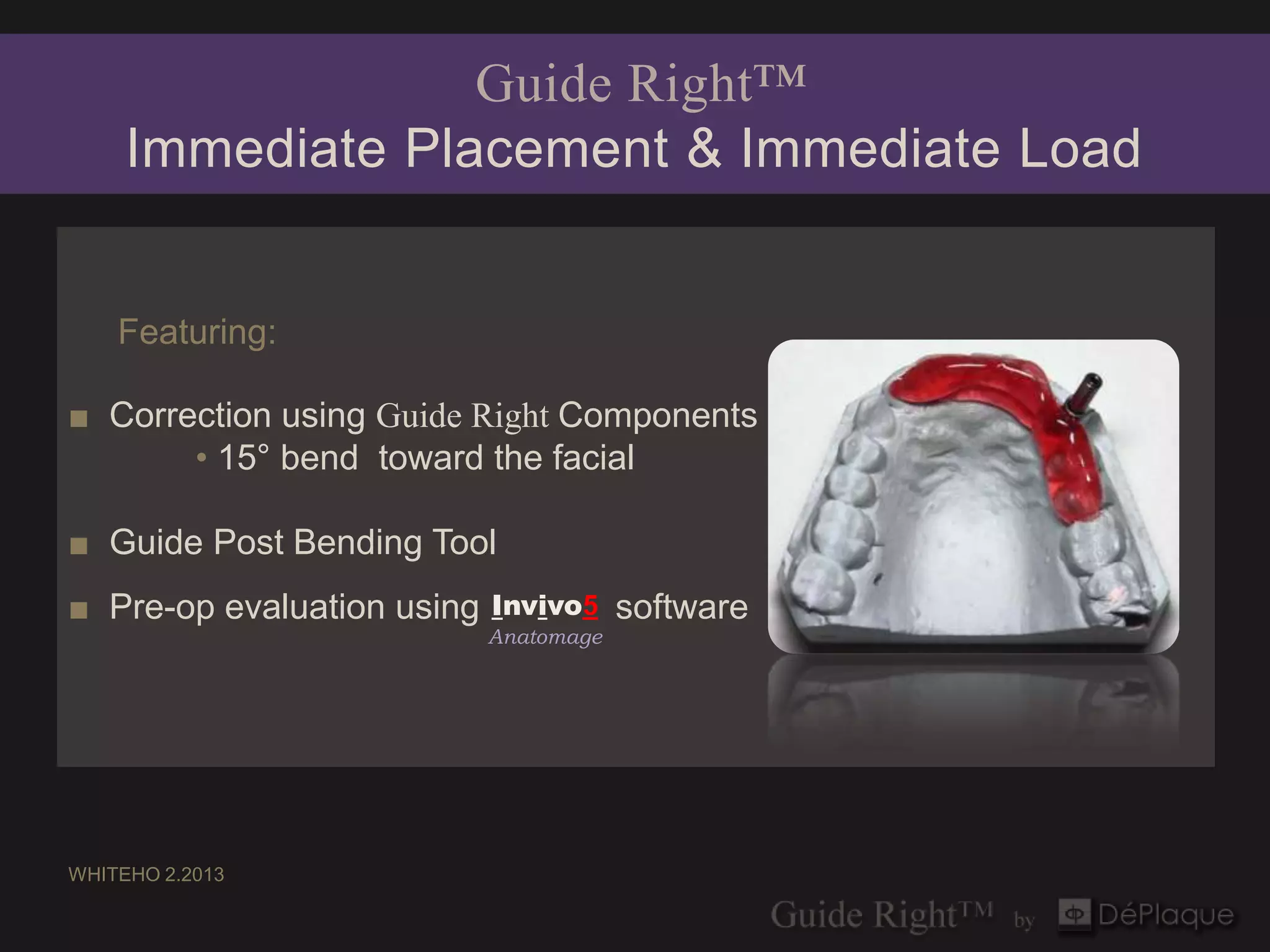

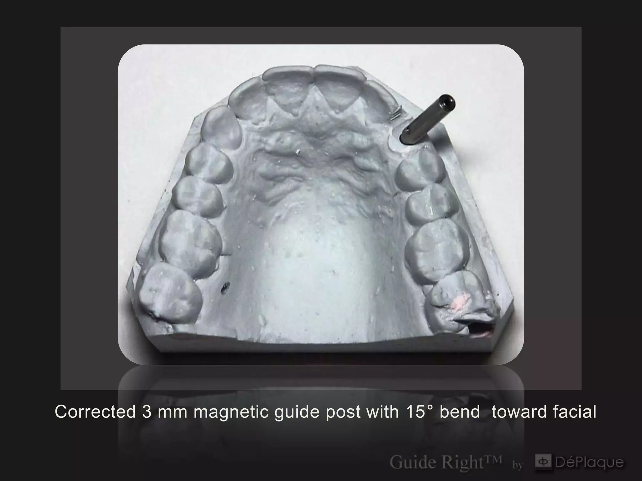
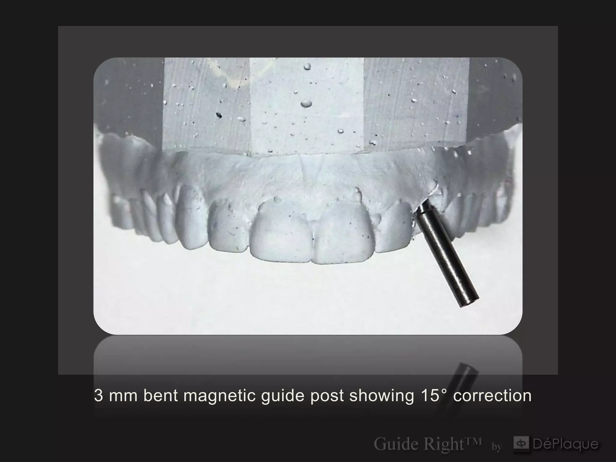
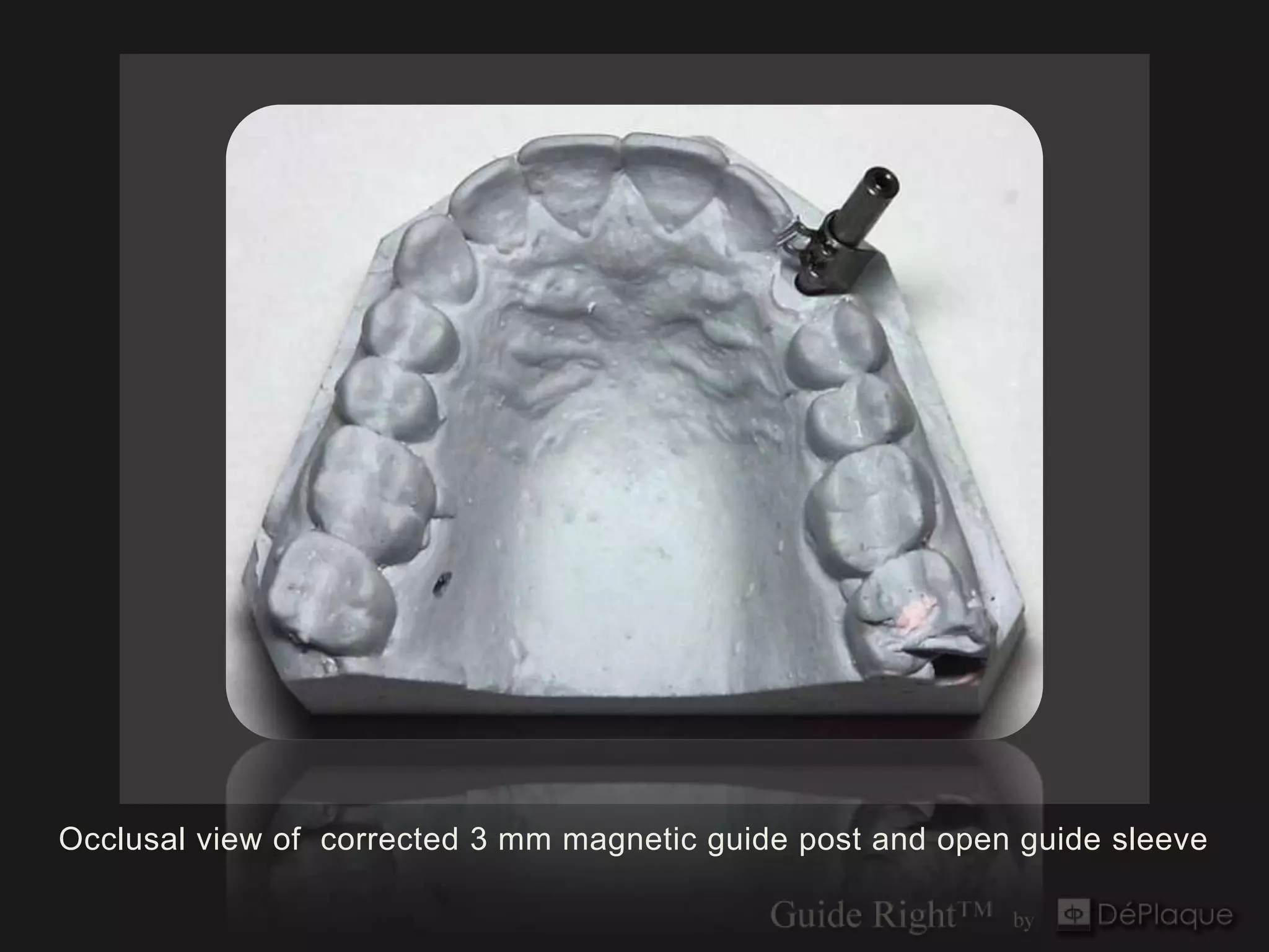
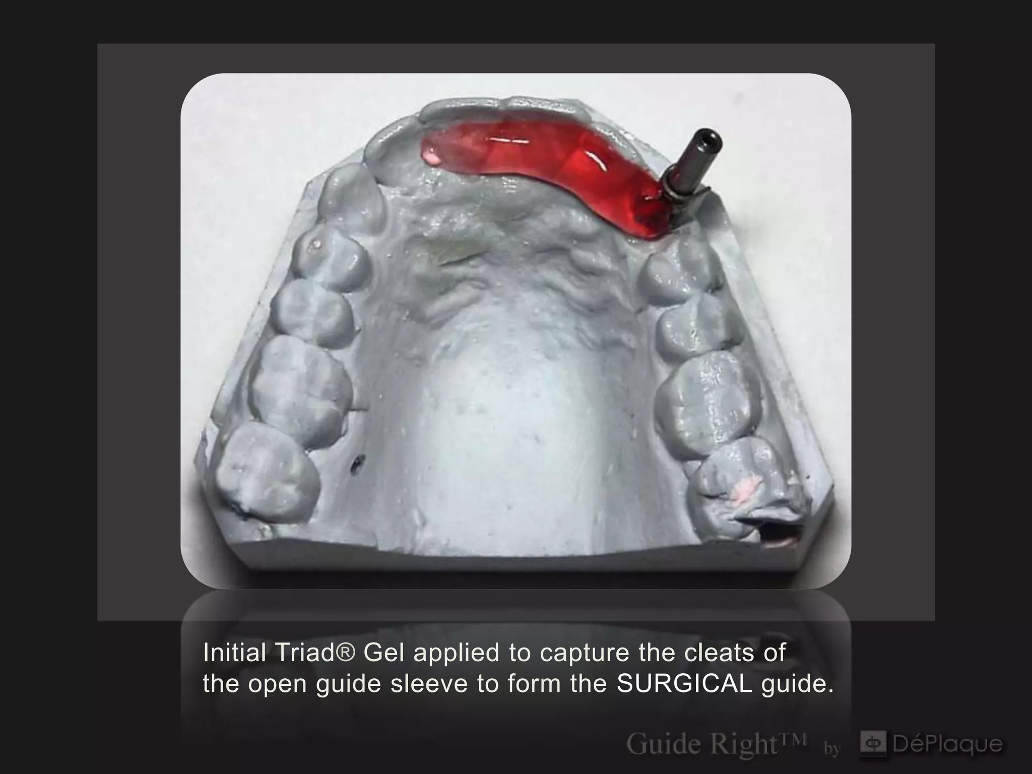
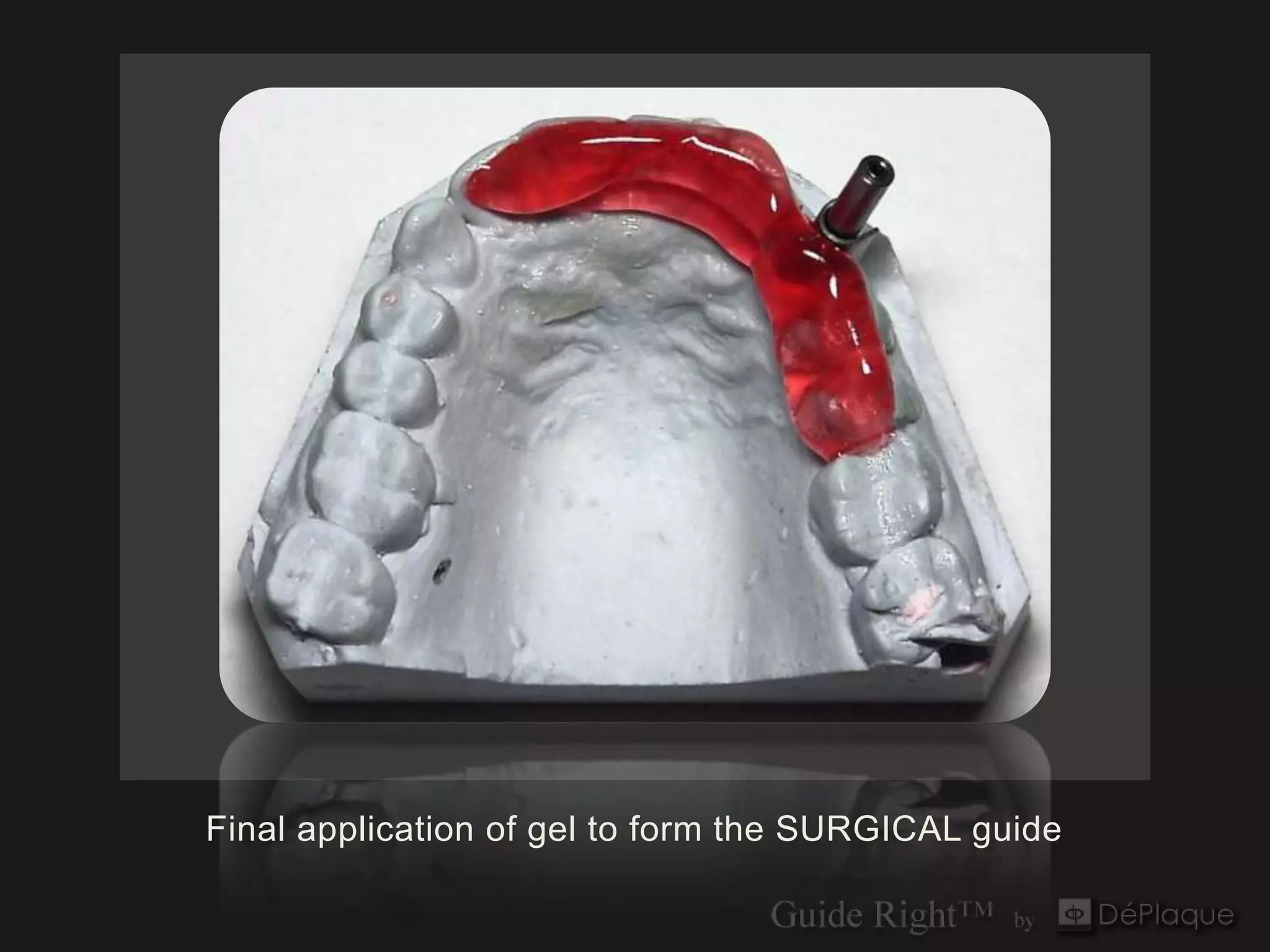
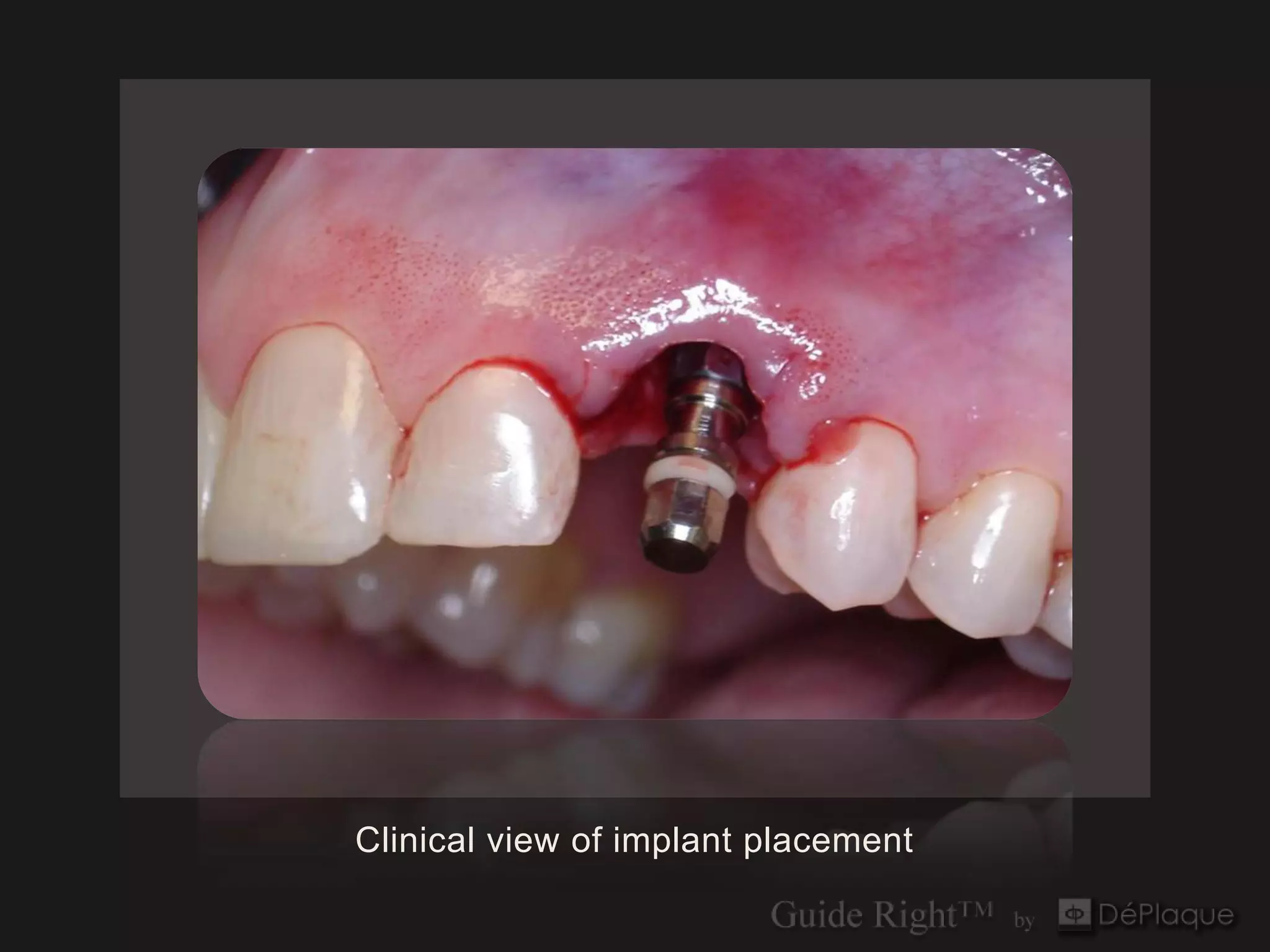
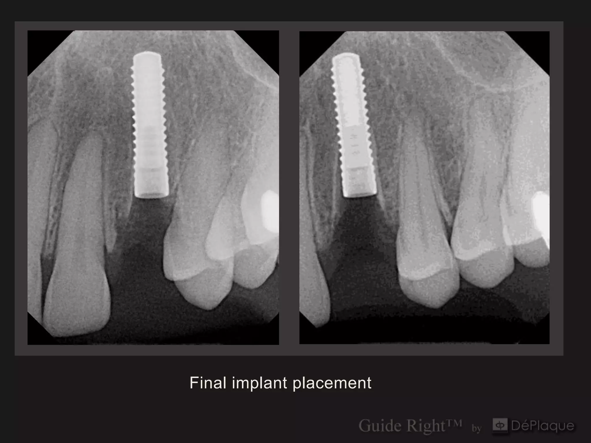
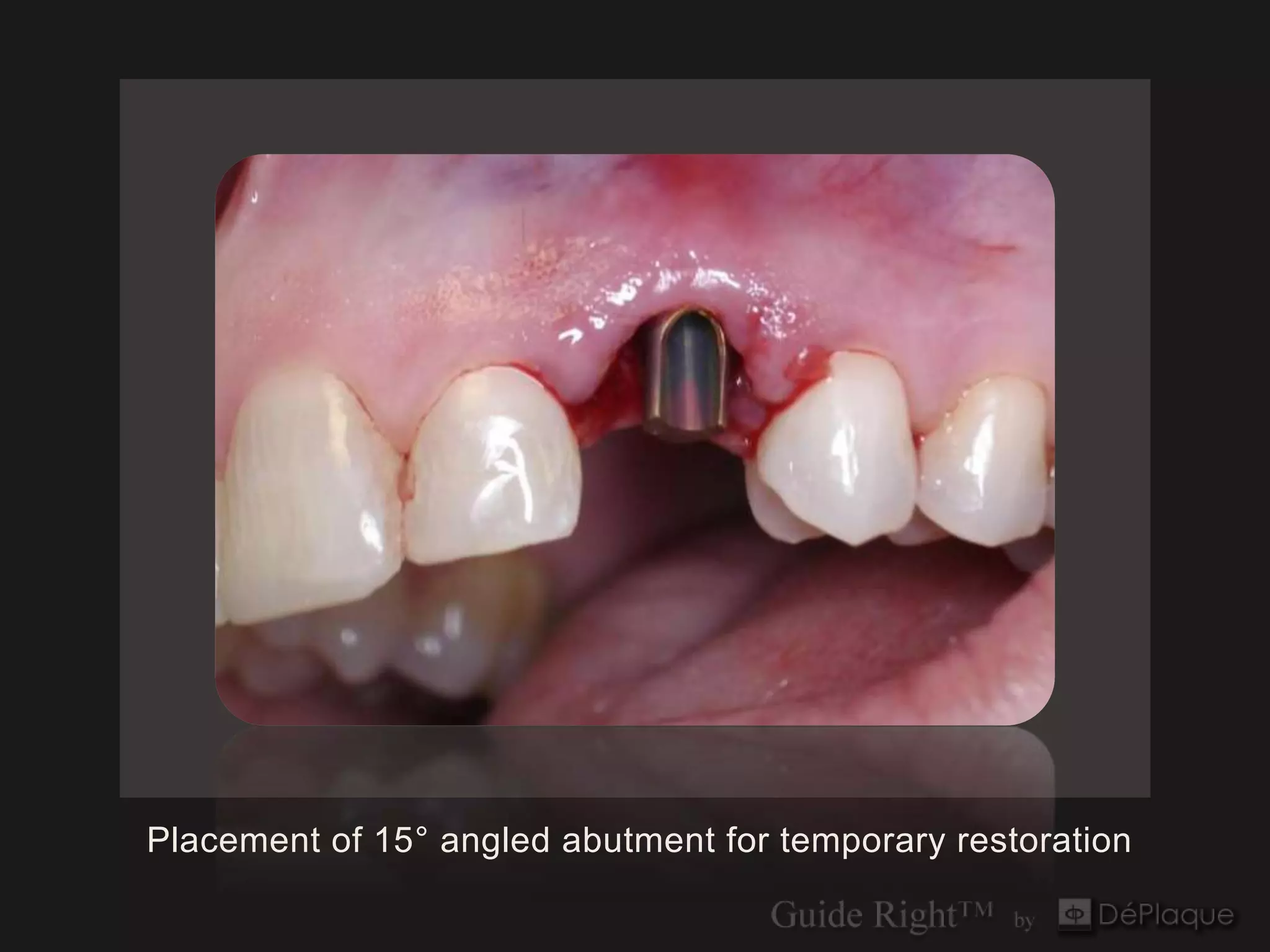
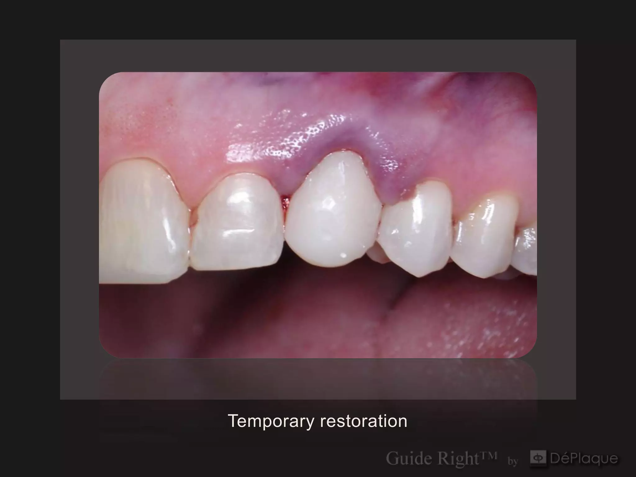
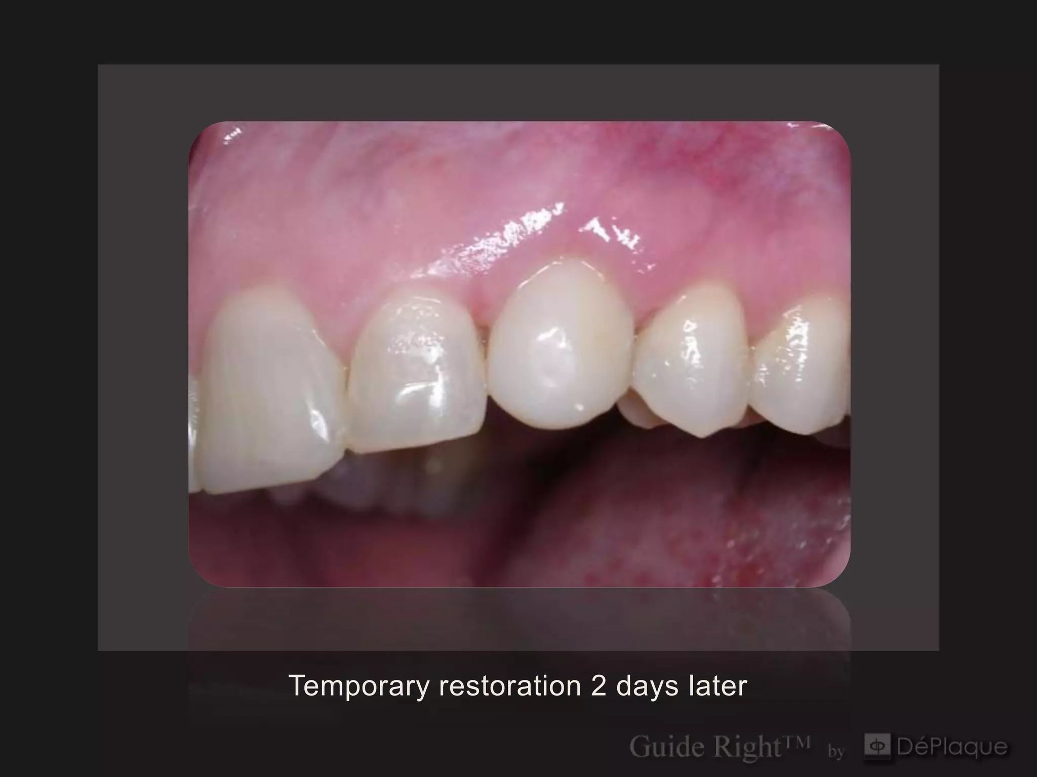
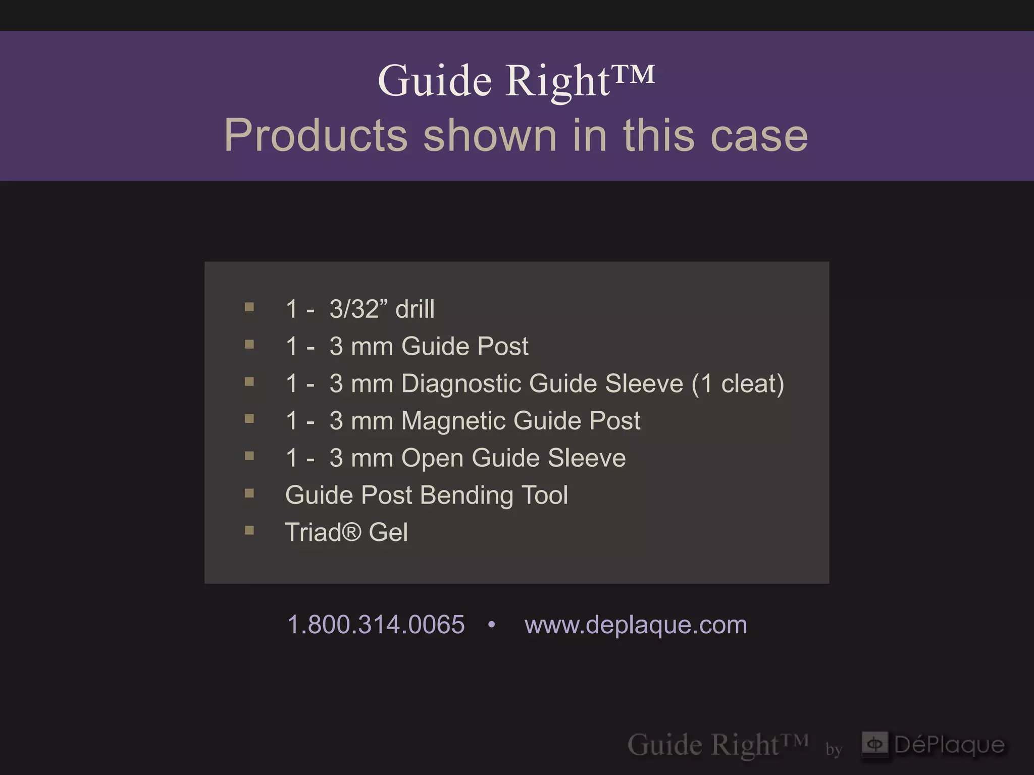
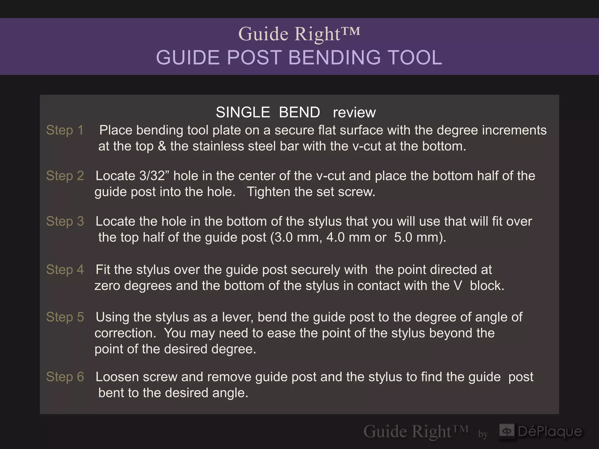
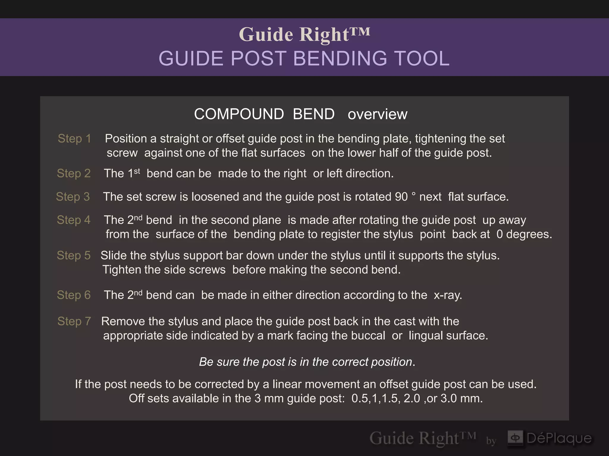

This document outlines the procedures for immediate implant placement and temporary restoration using the Guide Right system, emphasizing the importance of angular corrections in guide post placement. It provides detailed steps for evaluating and fabricating surgical guides and the use of infrastructure like Invivo5 software for accurate positioning. The Guide Right bending tool is highlighted for making precise adjustments to guide posts, ensuring effective and accurate implantation techniques.


