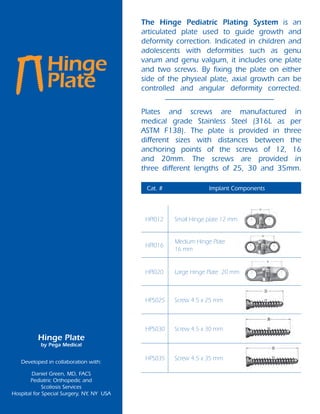
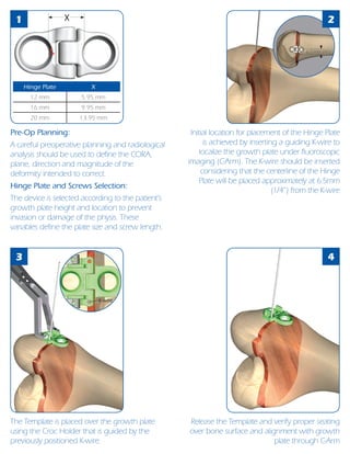
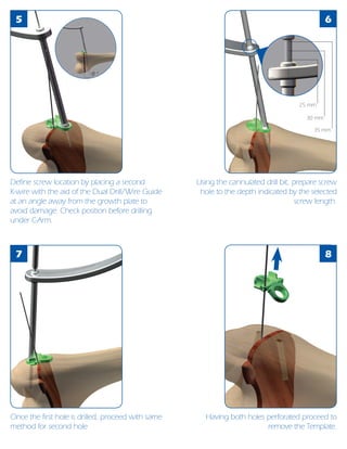
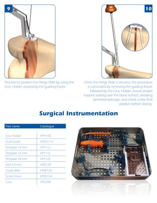
The Hinge Pediatric Plating System is an articulated plate used to guide growth and correct deformities in the legs of children and adolescents. It consists of one plate and two screws fixed on either side of the growth plate to control axial growth and correct angular deformities. The system comes in three plate sizes and three screw lengths to accommodate different growth plate heights and locations while preventing damage to the physis. The surgical technique involves pre-operative planning, selecting the appropriately sized plate and screws, inserting guiding pins under fluoroscopy, drilling screw holes at an angle away from the growth plate, securing the plate, and checking implant positioning.