Download as PDF, PPTX


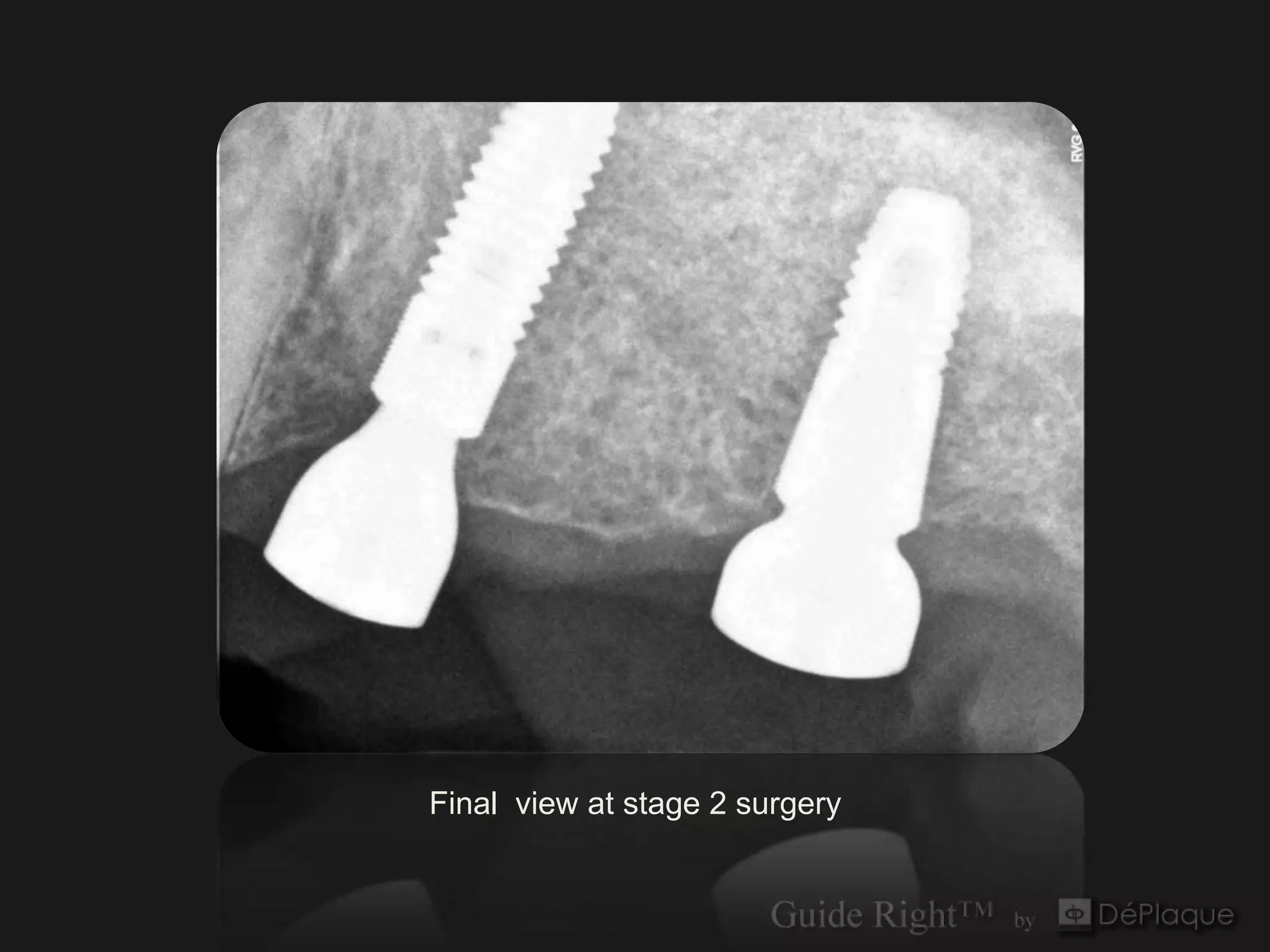
![Final Restoration
[mirror shot]](https://image.slidesharecdn.com/12maxillaryleftcaselinearcorrectionin2planes-130405121225-phpapp02/75/12-maxillary-left-case-linearcorrection-in2-planes-30-2048.jpg)

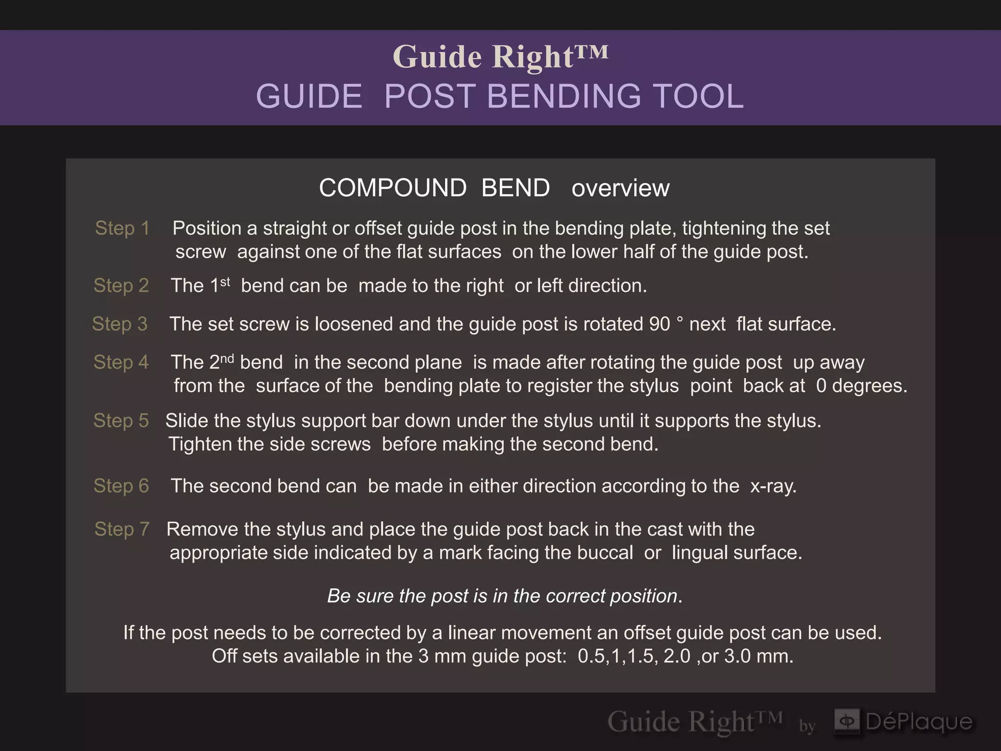
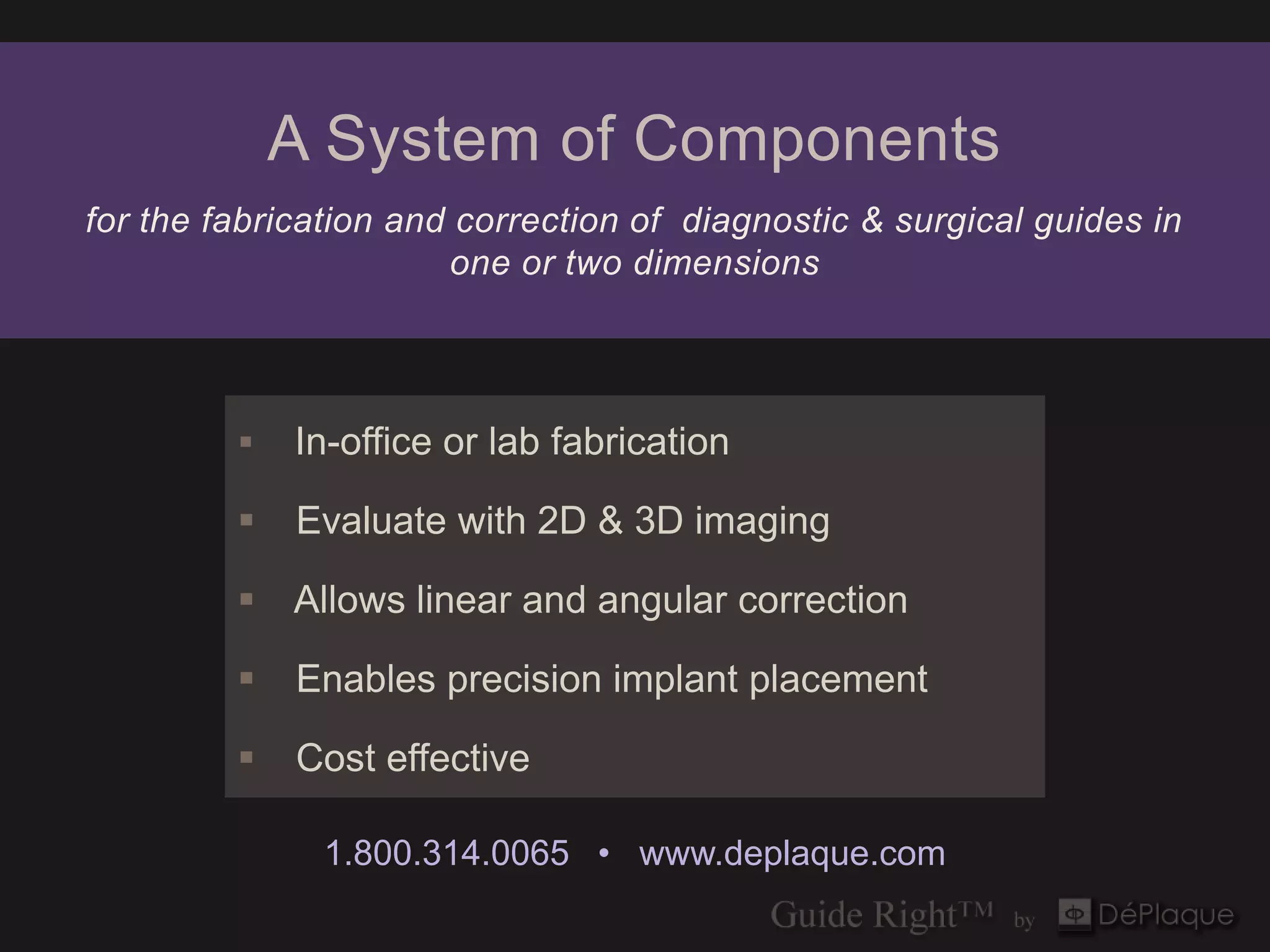

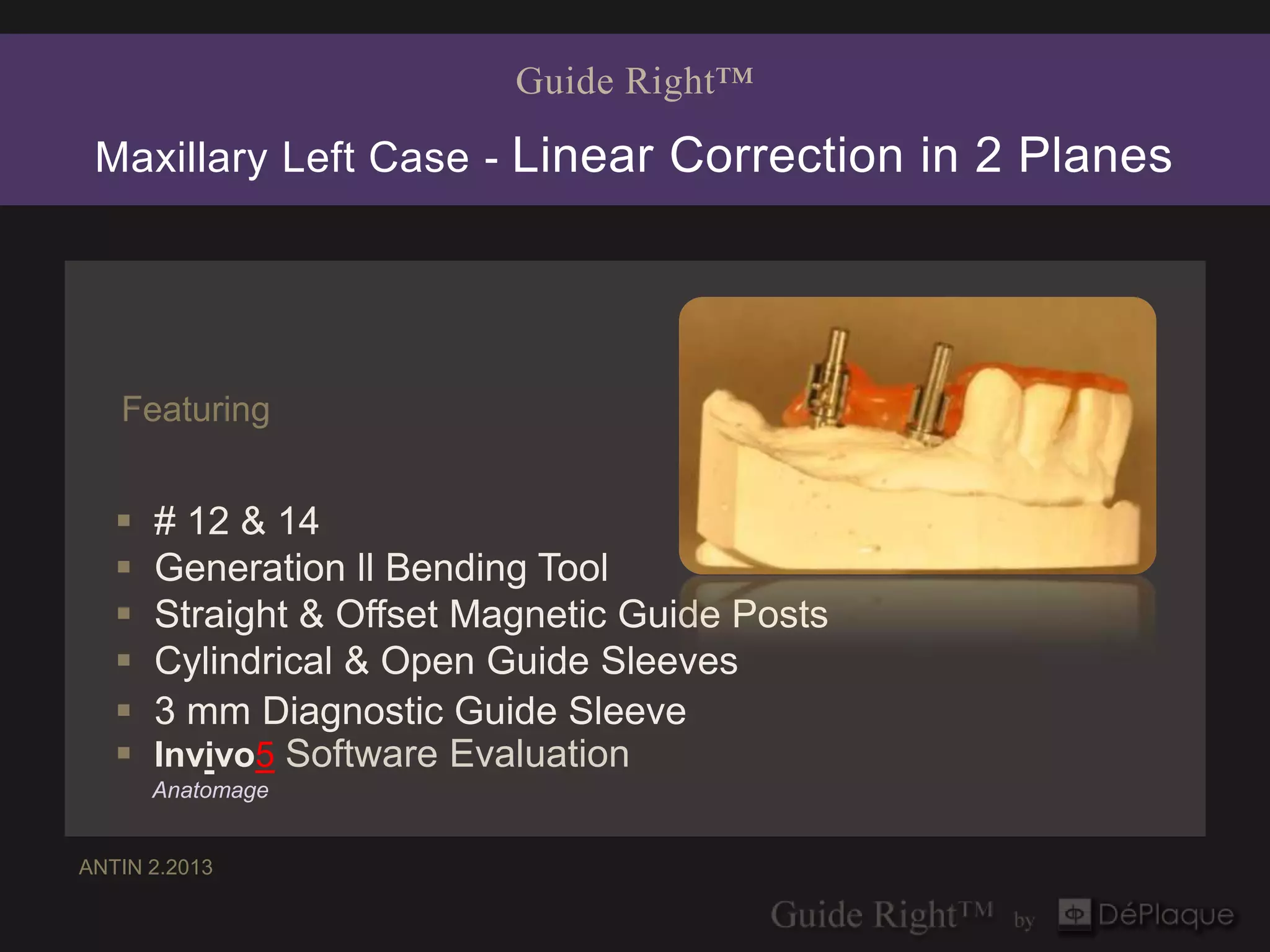
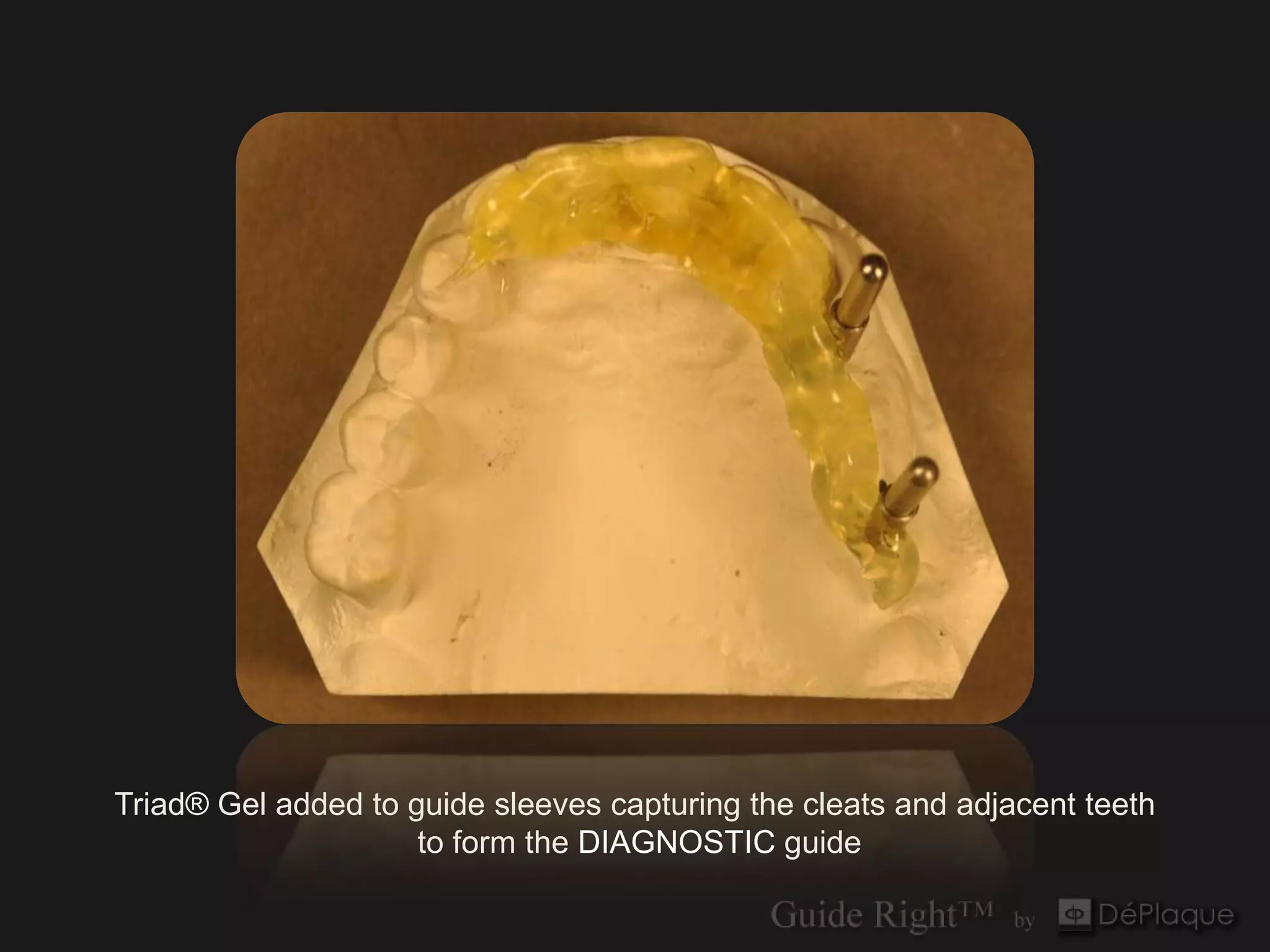
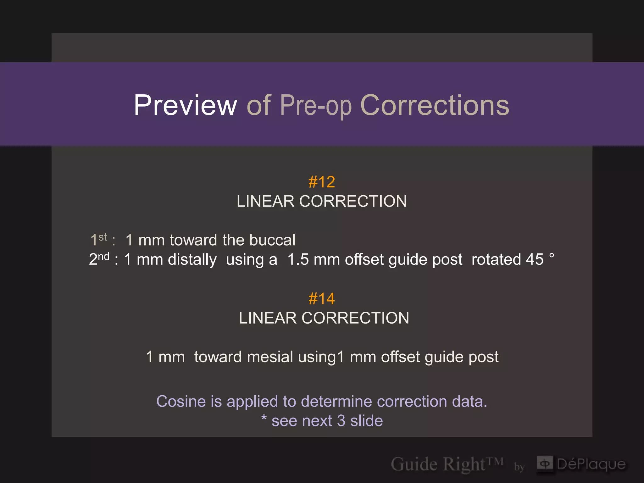
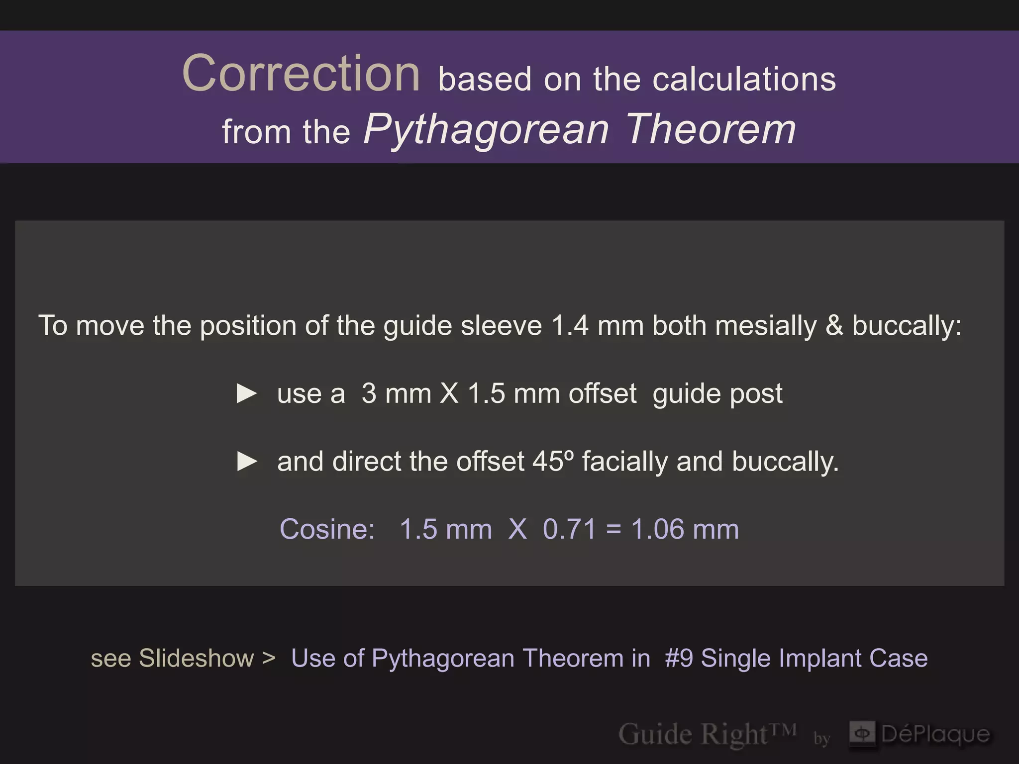
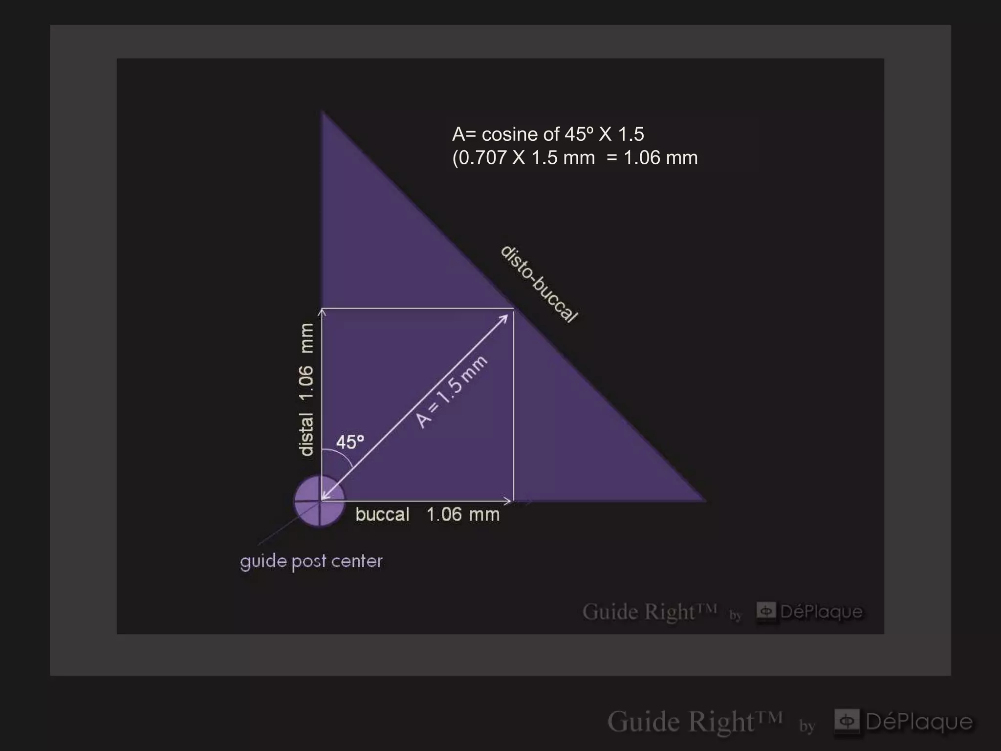
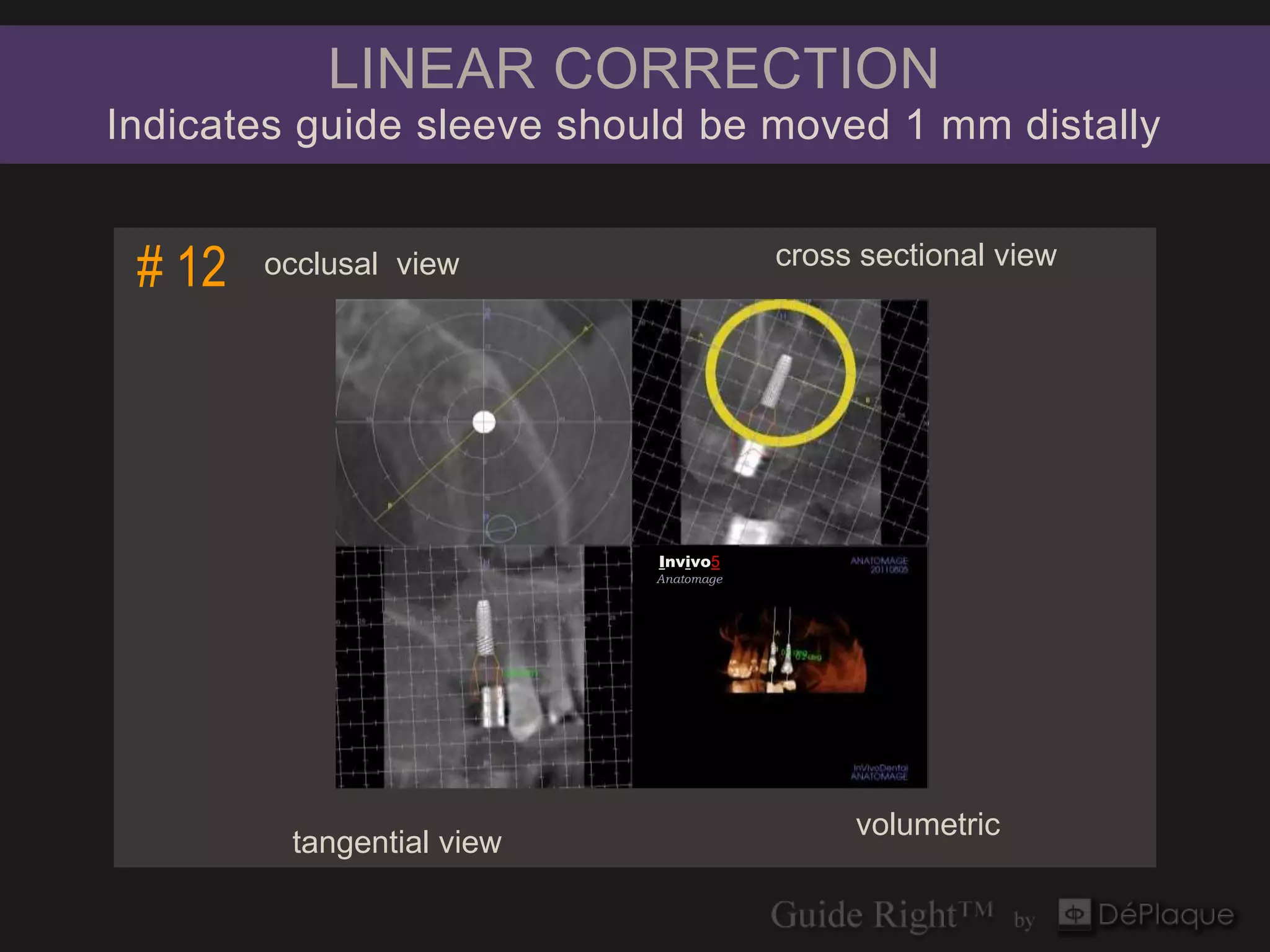
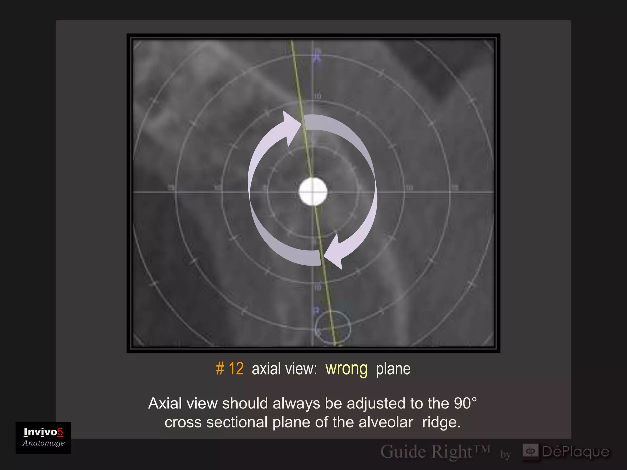
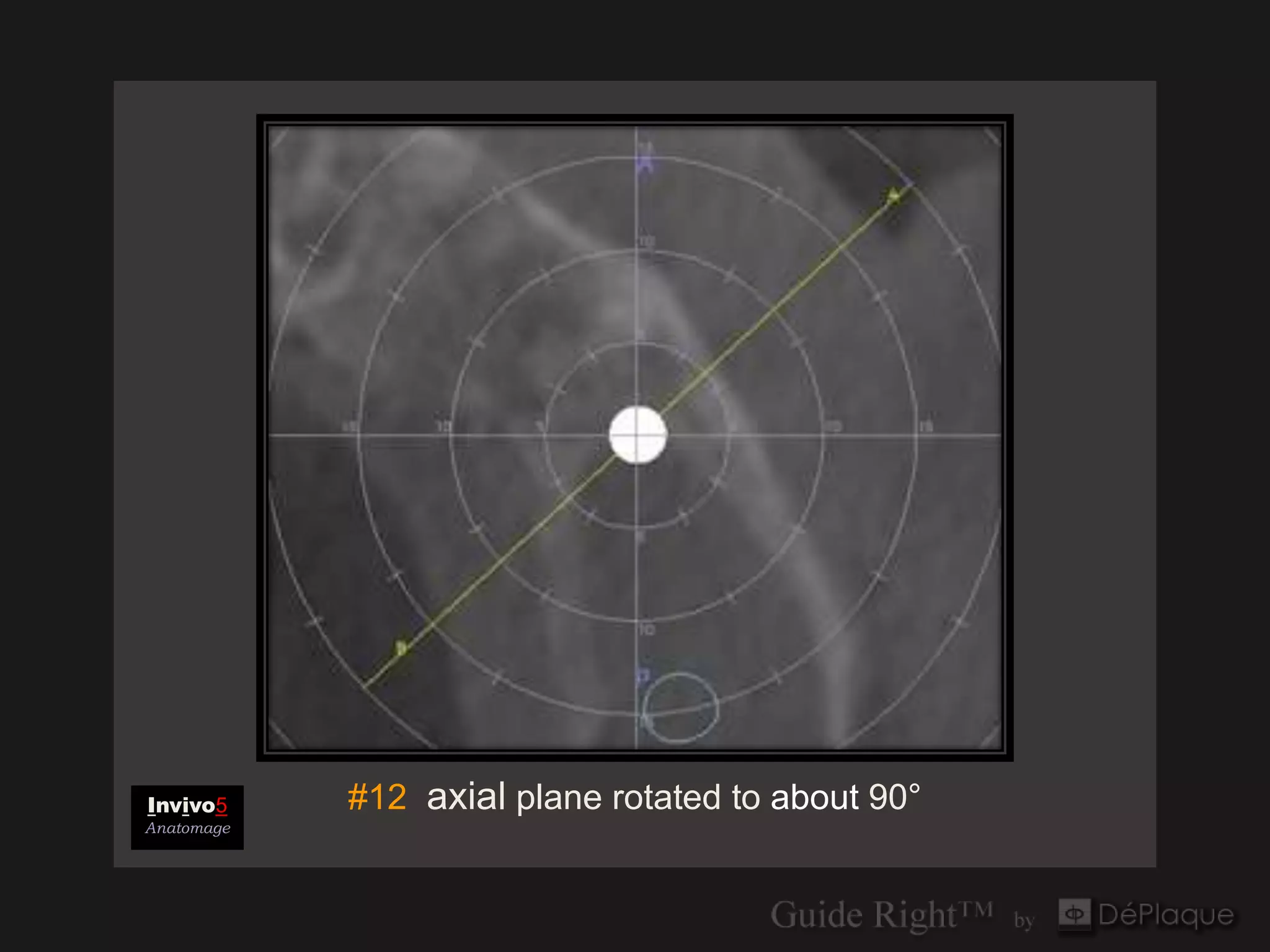
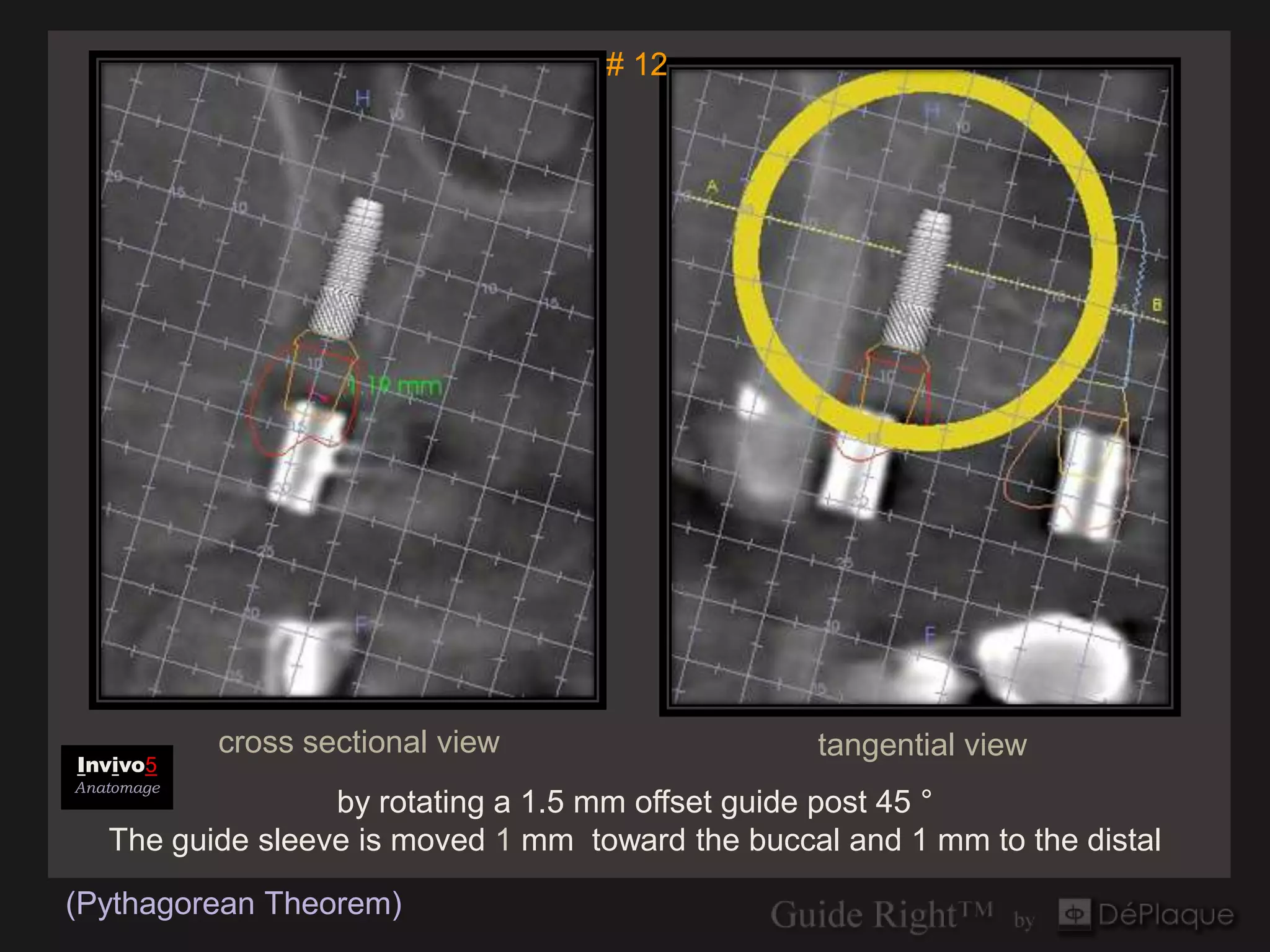
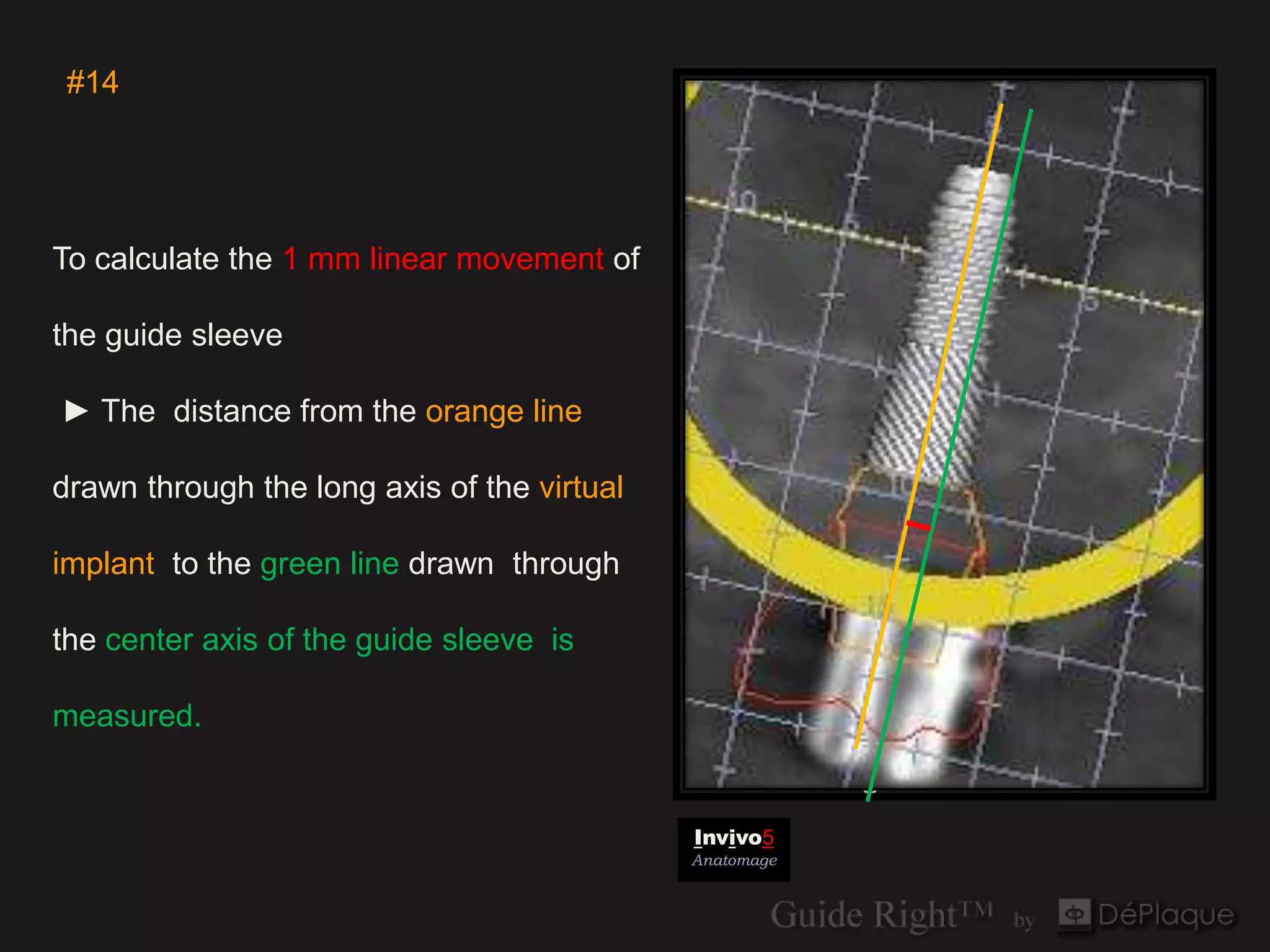
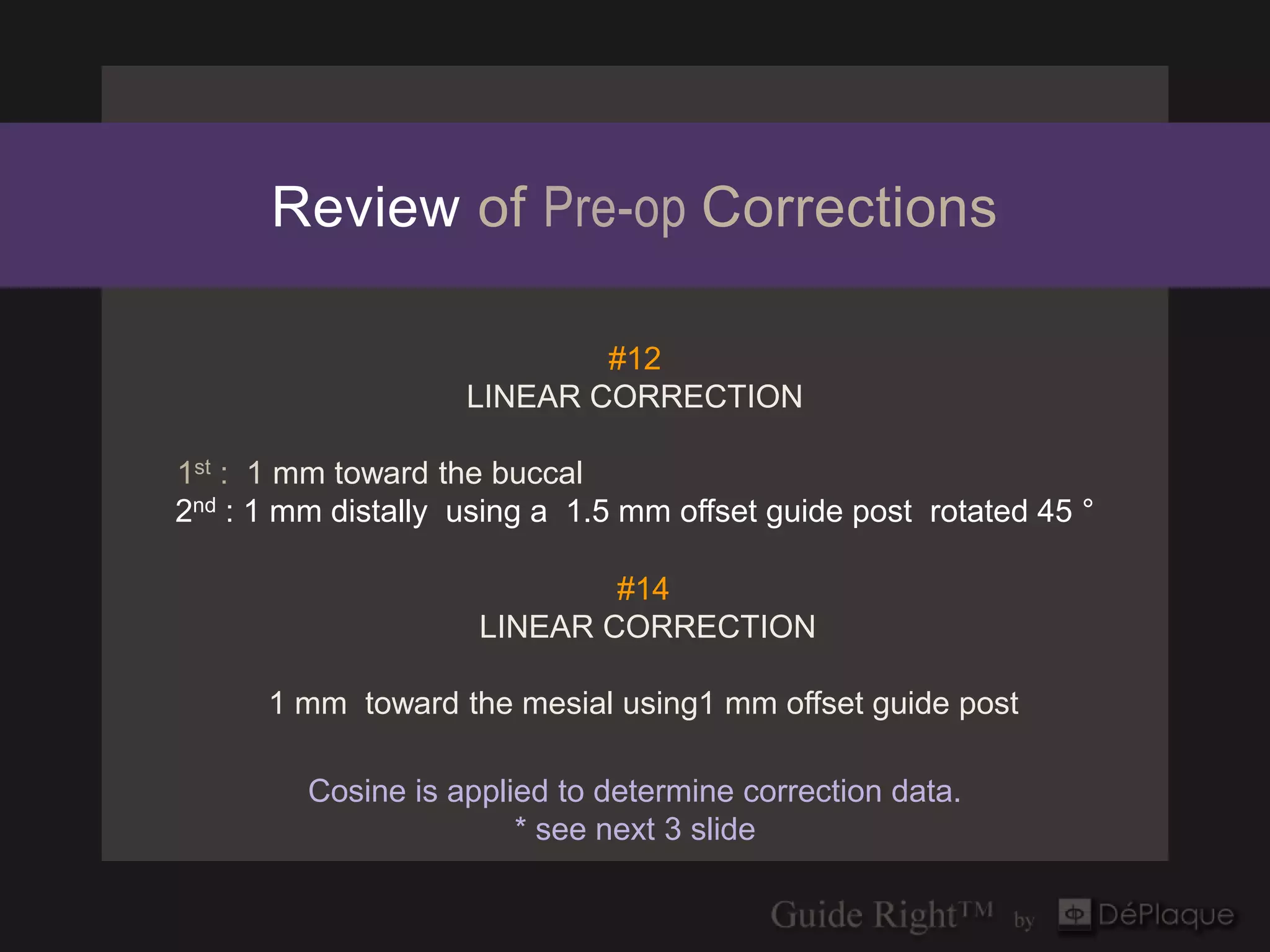
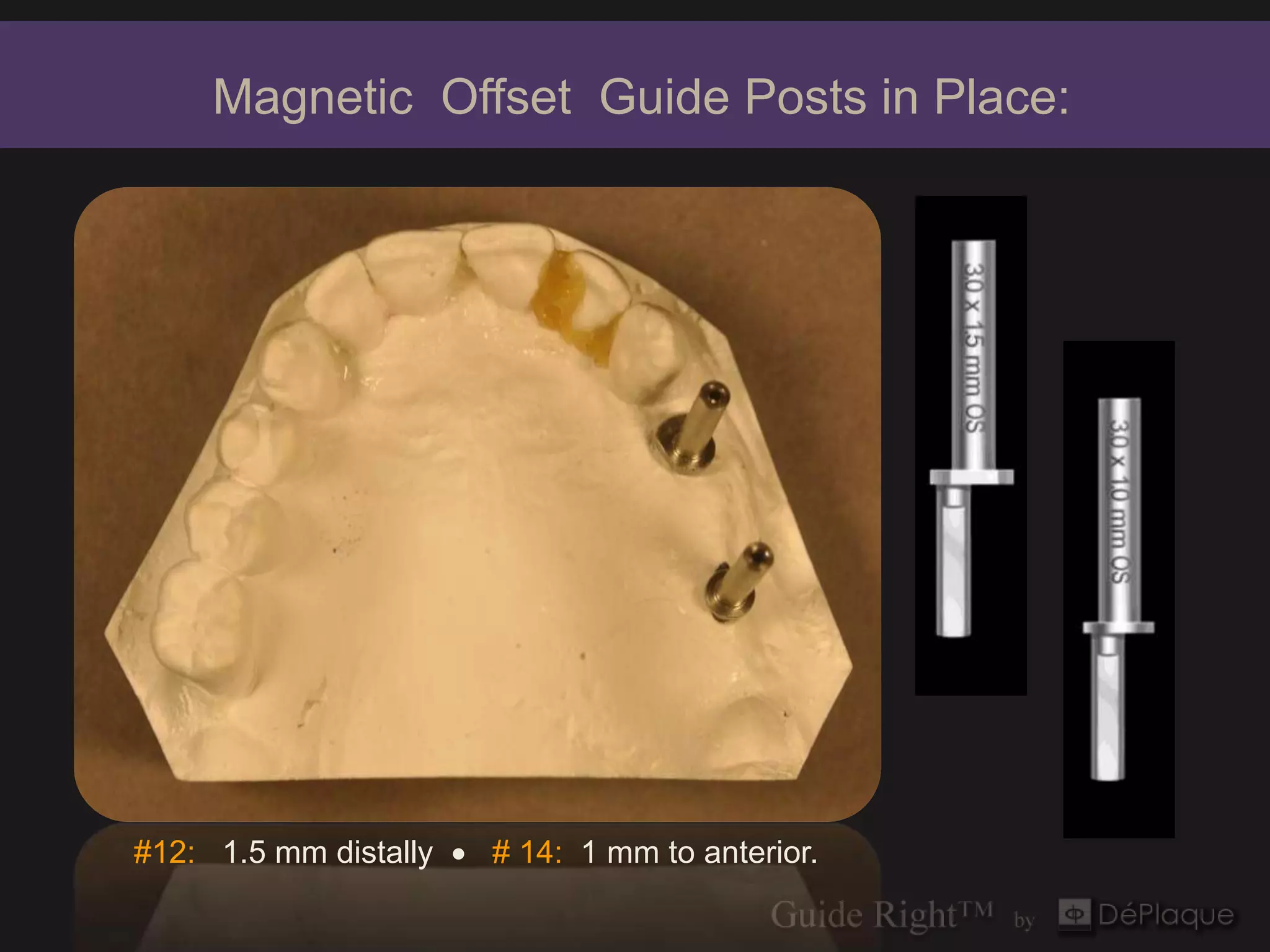
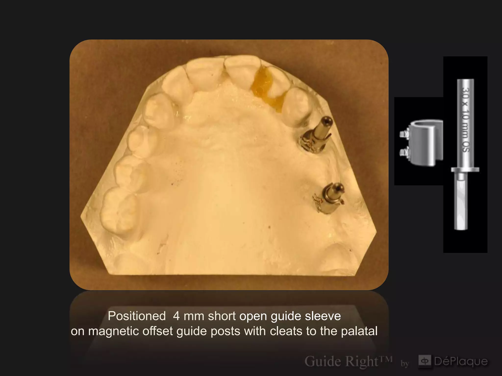
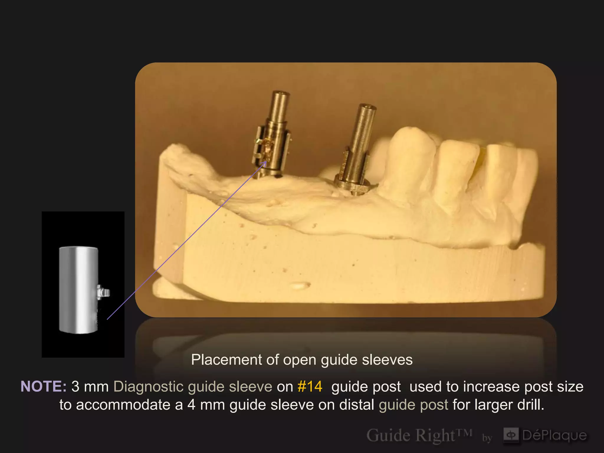
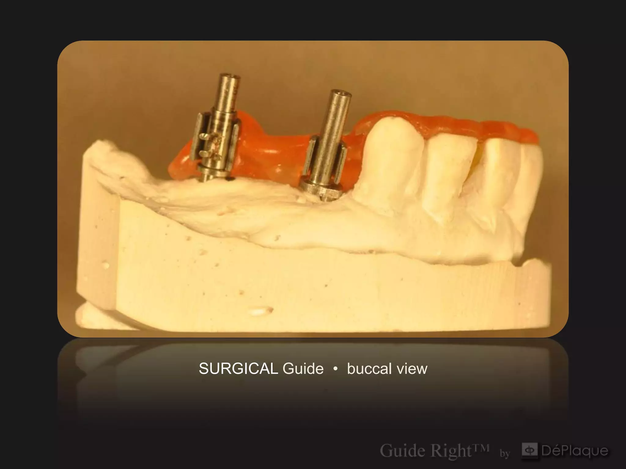
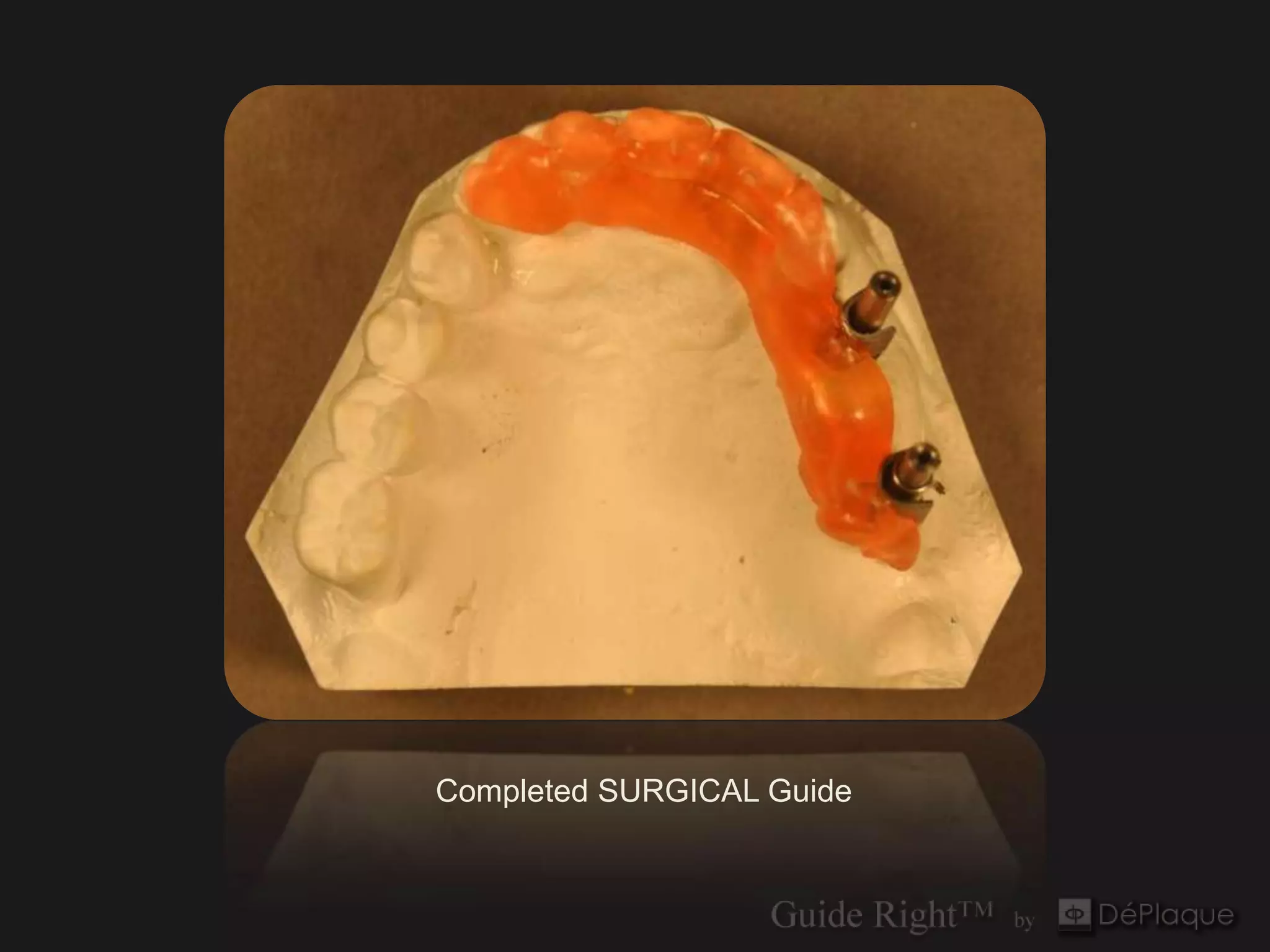
The document presents a detailed guide on the use of the Guide Right™ system for maxillary left case linear corrections in dental implant procedures, highlighting key components such as guide posts, sleeves, and software evaluations. It outlines the steps for measuring, correcting, and placing surgical guides along with specific calculations based on the Pythagorean theorem and cosine functions to achieve accurate placements. The guide emphasizes the importance of pre-operative evaluation and adjustments to ensure precision in implant placements.


