Download as PDF, PPTX
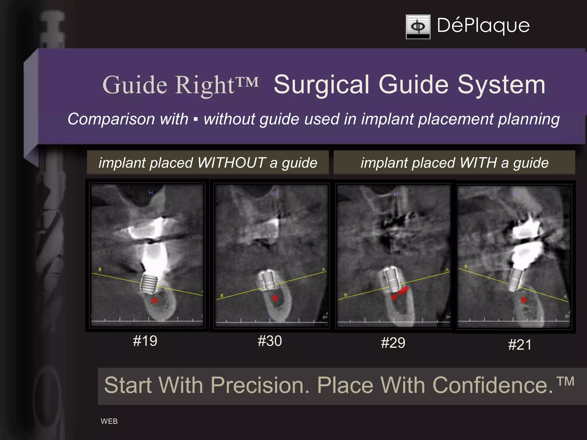
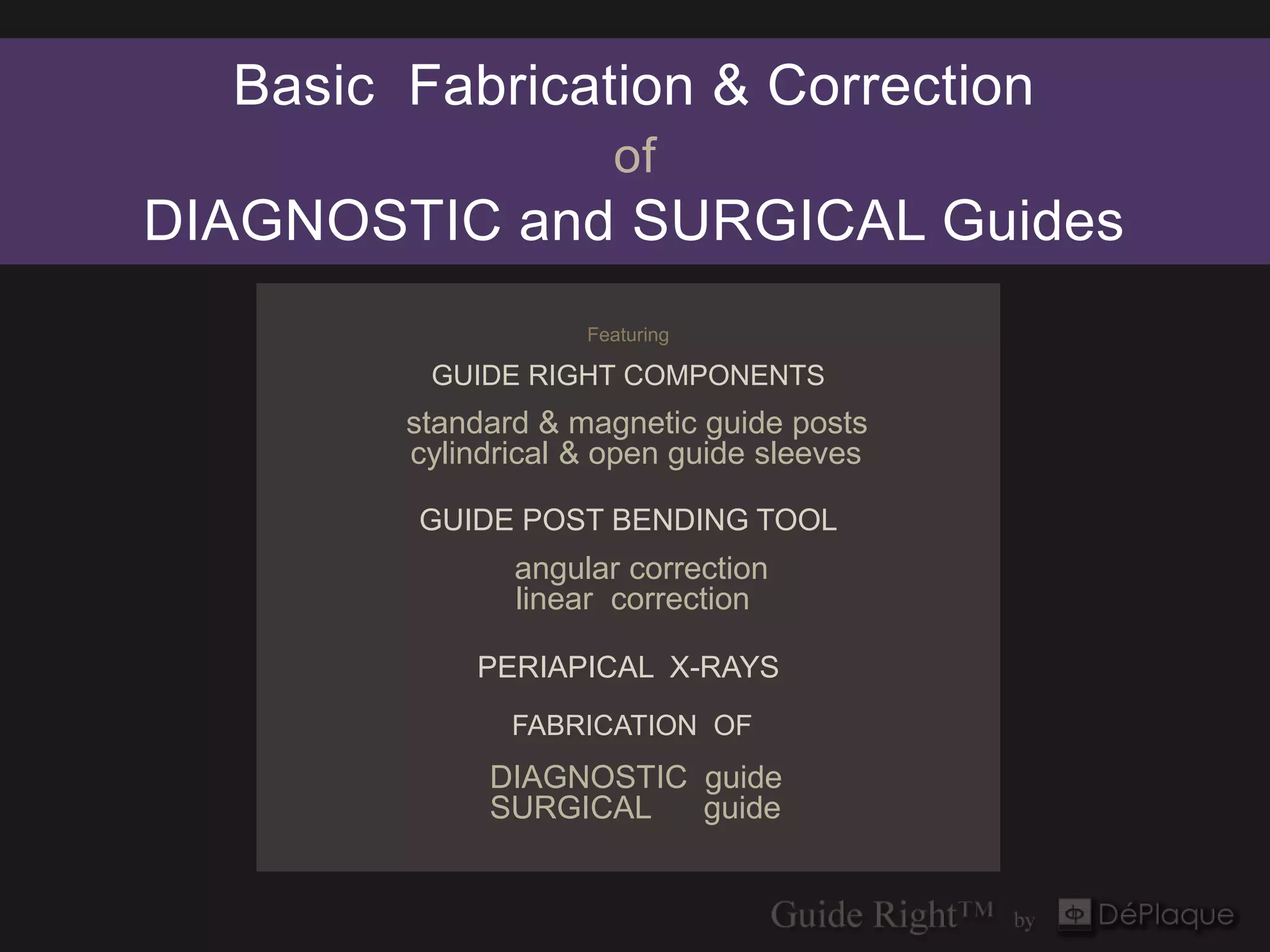
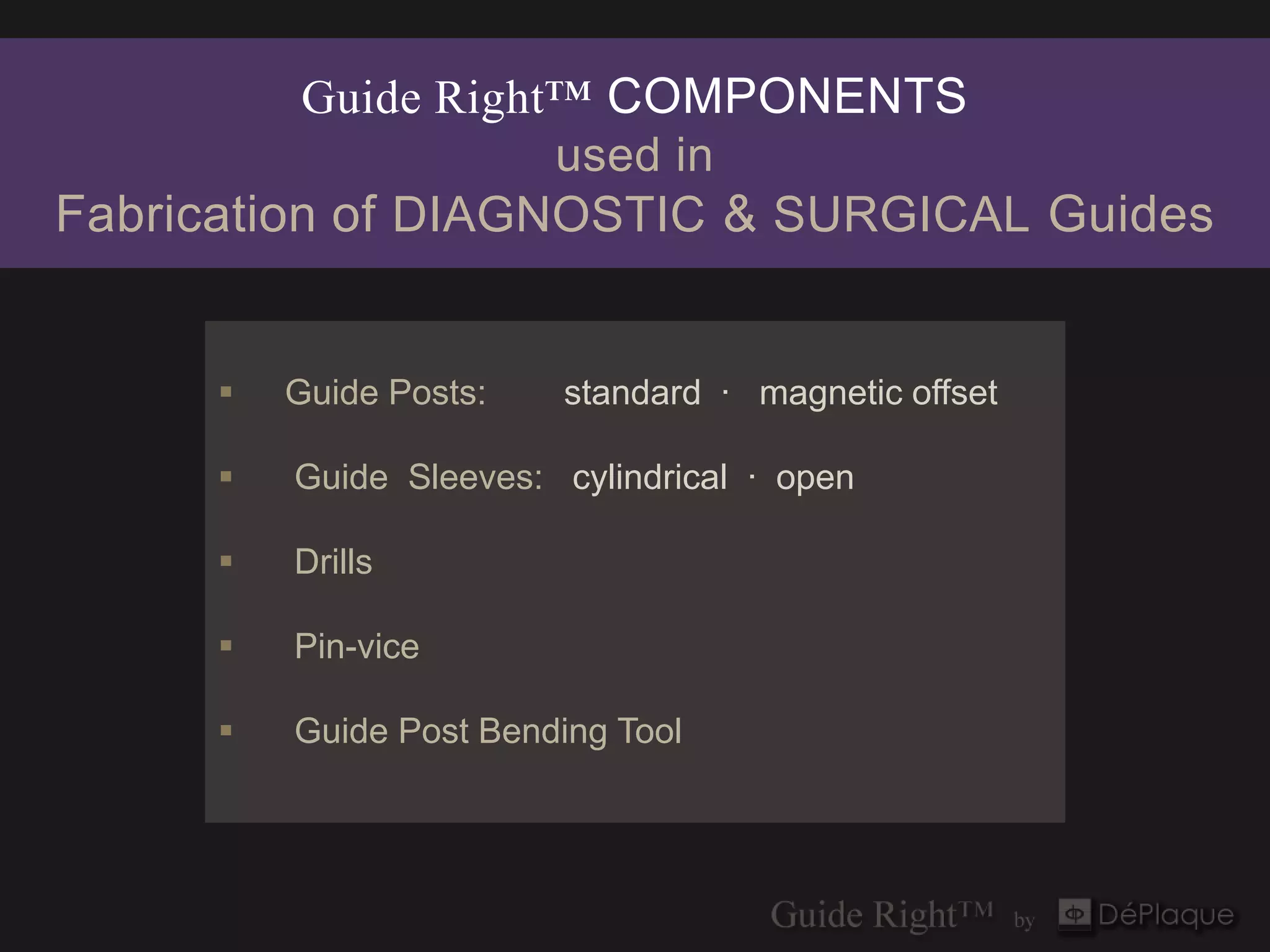
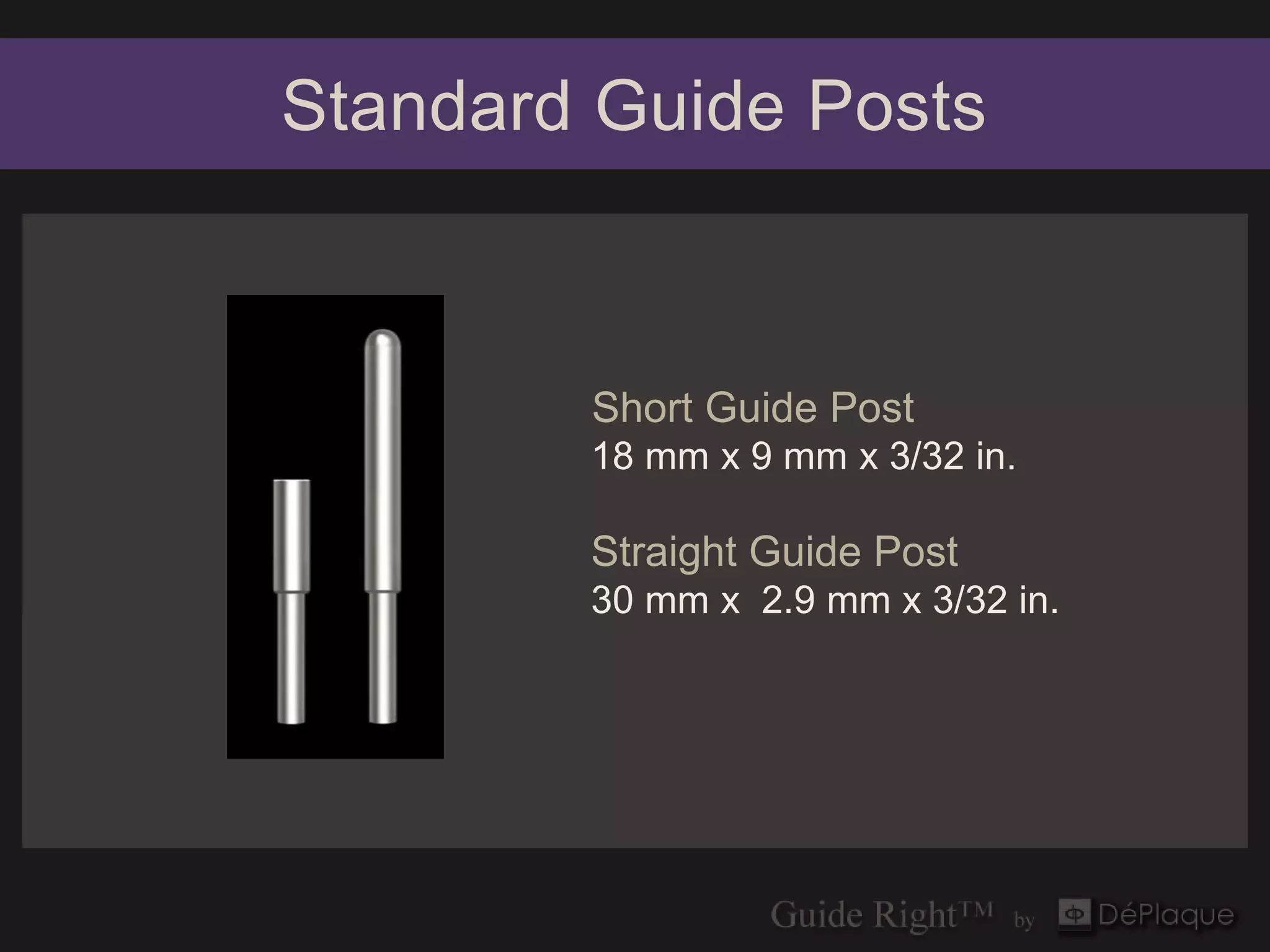
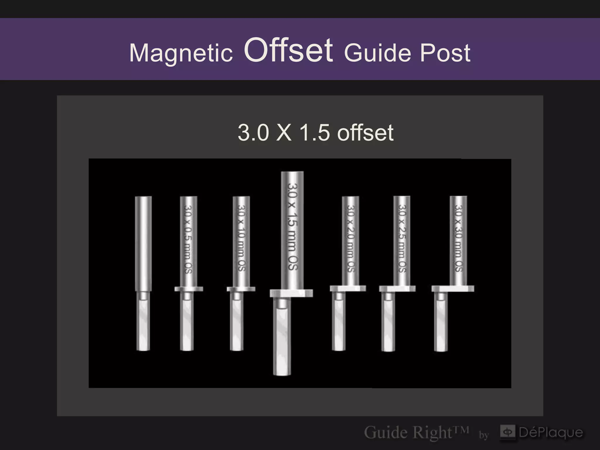
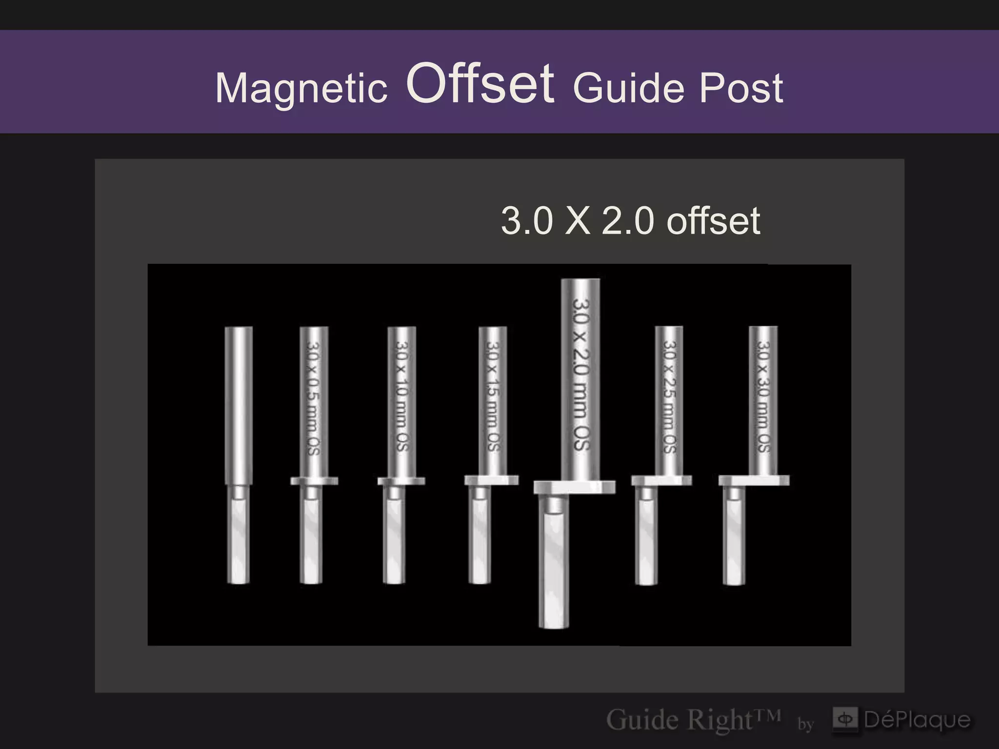
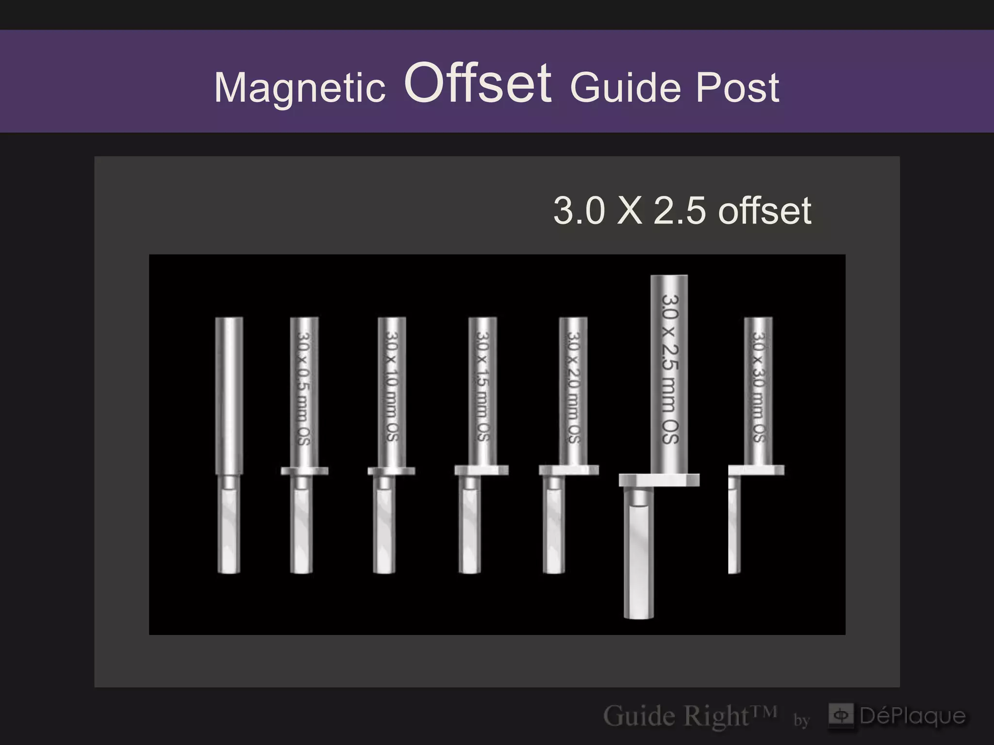
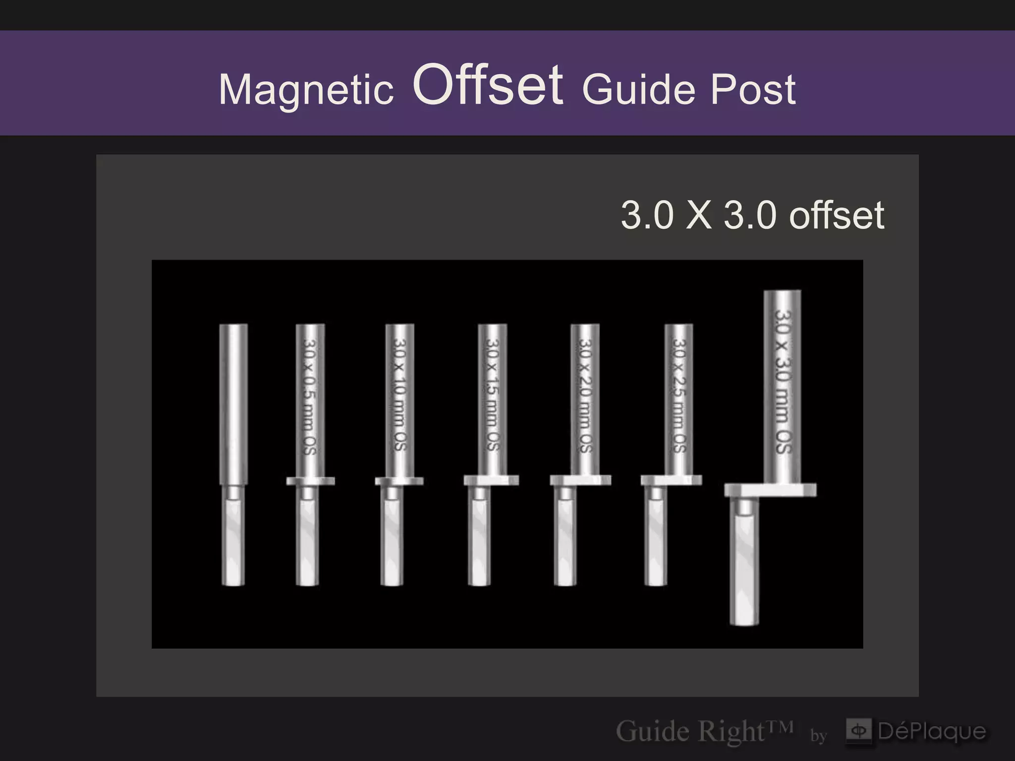
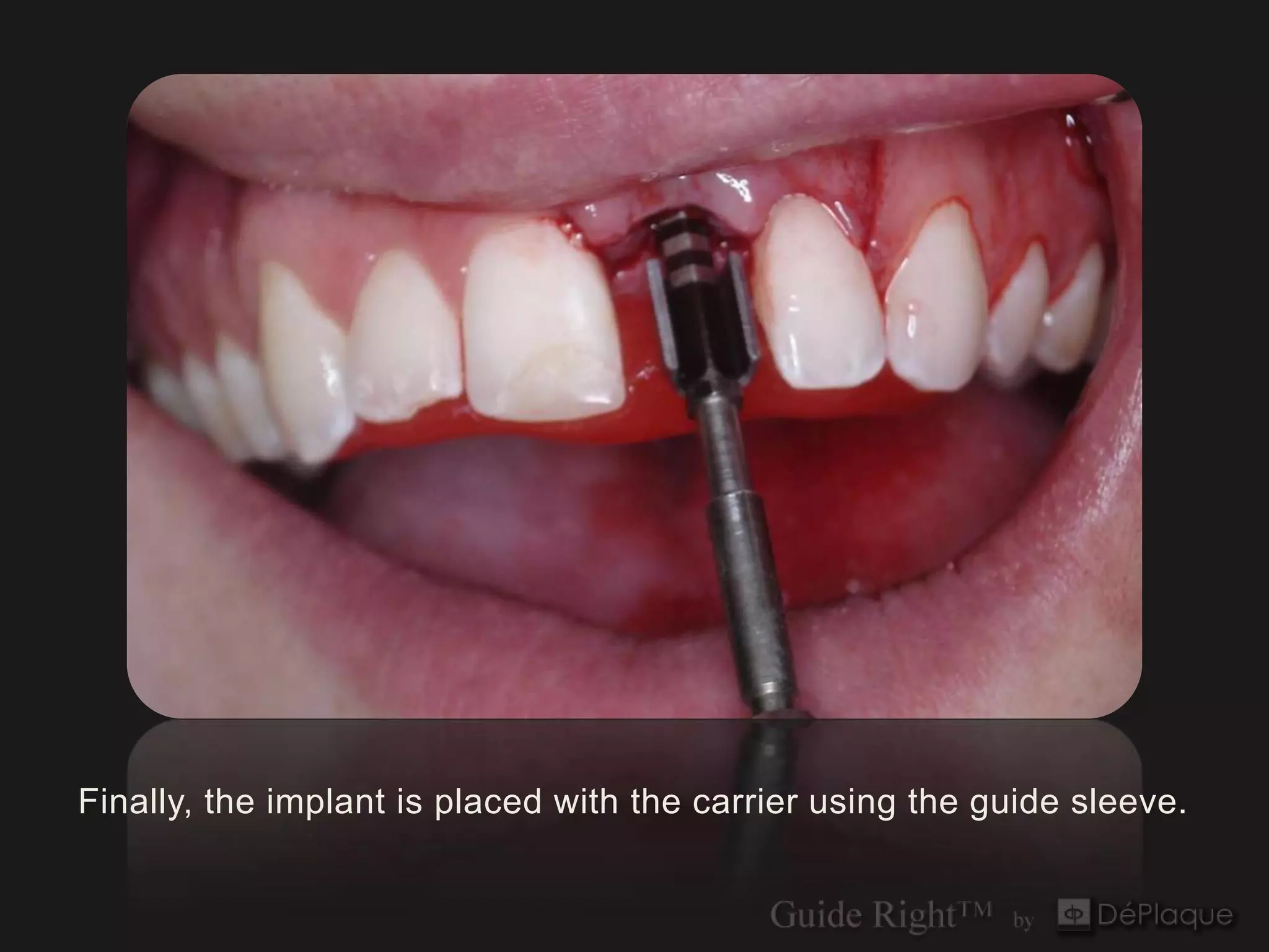
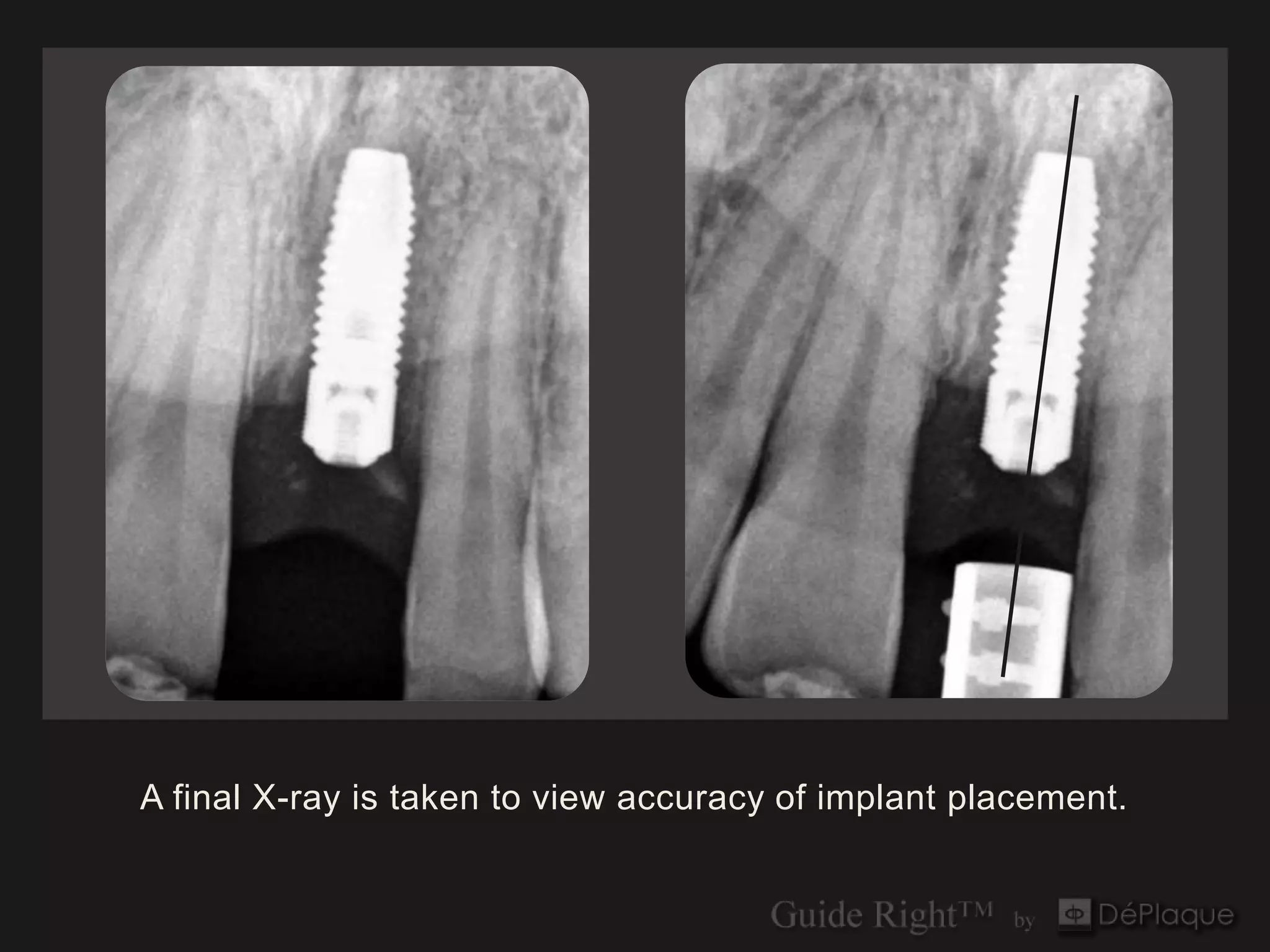
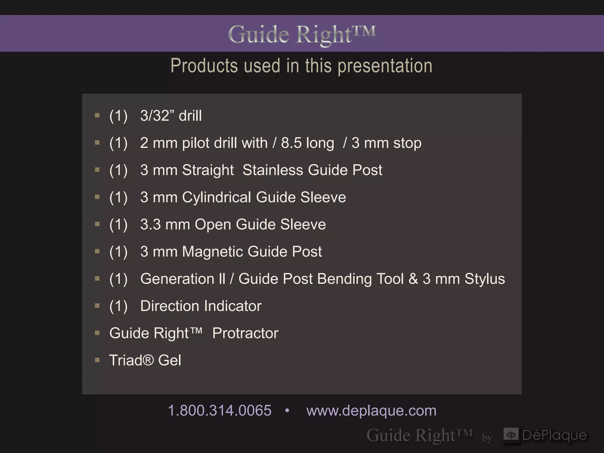
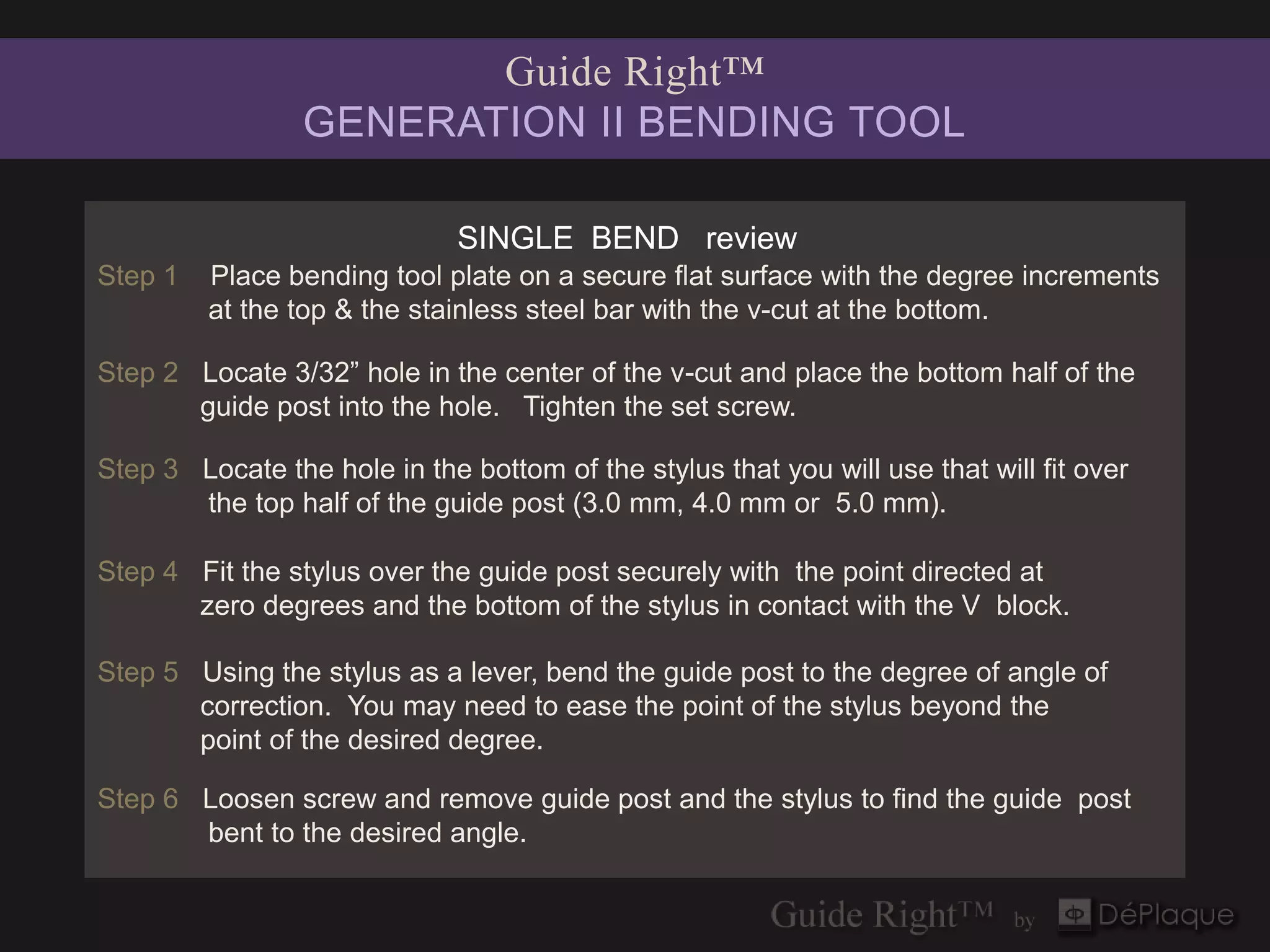
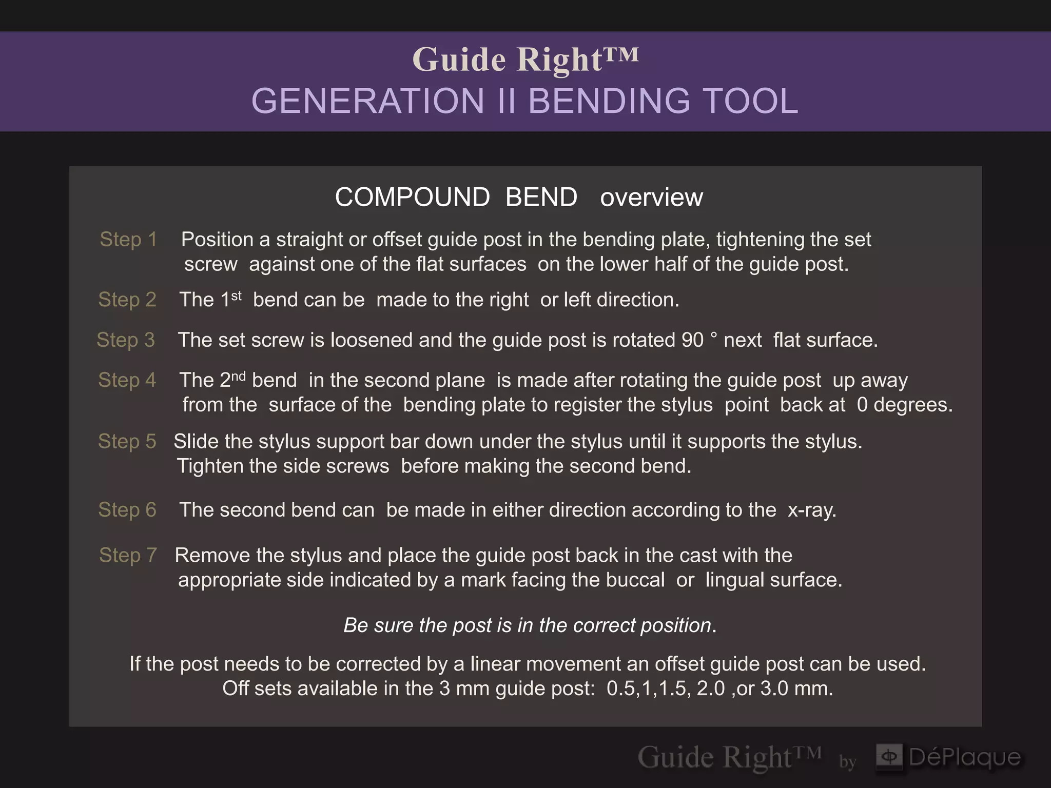

The Guide Right™ surgical guide system provides components for the accurate fabrication and adjustment of diagnostic and surgical guides for implant placement, utilizing both 2D and 3D imaging for precision. It addresses challenges associated with current 3D guides, such as fabrication delays and fitting issues, offering in-office or lab fabrication options to enhance efficiency and reduce costs. The system includes specialized tools and protocols for achieving optimal implant placement while minimizing risks of errors during surgery.


