

Recommended
More Related Content
What's hot
What's hot (20)
Viewers also liked
Similar to Experiment no. 10
Similar to Experiment no. 10 (20)
Recently uploaded
Recently uploaded (20)
Experiment no. 10
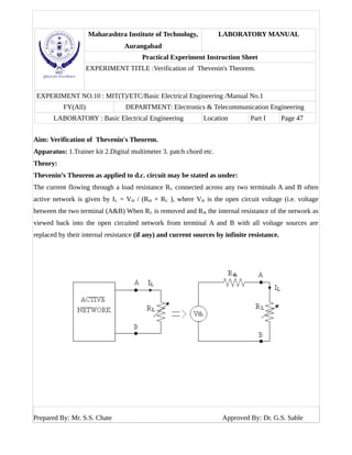
- 1. Maharashtra Institute of Technology, Aurangabad LABORATORY MANUAL Practical Experiment Instruction Sheet EXPERIMENT TITLE :Verification of Thevenin's Theorem. EXPERIMENT NO.10 : MIT(T)/ETC/Basic Electrical Engineering /Manual No.1 FY(All) DEPARTMENT: Electronics & Telecommunication Engineering LABORATORY : Basic Electrical Engineering Location Part I Page 47 Aim: Verification of Thevenin's Theorem. Apparatus: 1.Trainer kit 2.Digital multimeter 3. patch chord etc. Theory: Thevenin’s Theorem as applied to d.c. circuit may be stated as under: The current flowing through a load resistance RL connected across any two terminals A and B often active network is given by IL = Vth / (Rth + RL ), where Vth is the open circuit voltage (i.e. voltage between the two terminal (A&B) When RL is removed and Rth the internal resistance of the network as viewed back into the open circuited network from terminal A and B with all voltage sources are replaced by their internal resistance (if any) and current sources by infinite resistance. Prepared By: Mr. S.S. Chate Approved By: Dr. G.S. Sable
- 2. Maharashtra Institute of Technology, Aurangabad LABORATORY MANUAL Practical Experiment Instruction Sheet EXPERIMENT TITLE :Verification of Thevenin's Theorem. EXPERIMENT NO.10 : MIT(T)/ETC/Basic Electrical Engineering /Manual No.1 FY(All) DEPARTMENT: Electronics & Telecommunication Engineering LABORATORY : Basic Electrical Engineering Location Part I Page 48 Connection diagram Component values: R1 = R2 = R3 = R4 = 100 ohms. Procedure: 1. Switch ON the trainer kit by connecting to main. 2. Connect the voltmeter provided in kit across V1 and adjust V1. 3. Connect AB and GH and Ammeter as shown in circuit diagram (Presently don’t connect R4 in the circuit. 4. Adjust load current ‘IL’ by adjust RL. 5. Now, to calculate this load current using thevenin’s theorem, remove the current meter jumper links (i.e. RL will be removed). 6. Now measure the open circuit voltage between E & K i.e. Vth. 7. Now disconnect the jumper links of V1 (i.e. AB &GH) and short the resistances by connecting B & H by patch chord. Prepared By: Mr. S.S. Chate Approved By: Dr. G.S. Sable
- 3. Maharashtra Institute of Technology, Aurangabad LABORATORY MANUAL Practical Experiment Instruction Sheet EXPERIMENT TITLE :Verification of Thevenin's Theorem. EXPERIMENT NO.10 : MIT(T)/ETC/Basic Electrical Engineering /Manual No.1 FY(All) DEPARTMENT: Electronics & Telecommunication Engineering LABORATORY : Basic Electrical Engineering Location Part I Page 49 8. Measure equivalent resistance at the point RL removed (between E & K) i.e. Rth and calculate the load current with thevenin’s theorem using equation. IL (Calculated) = Vth / (Rth + RL). Compared the IL measured and IL Calculated. 9. Repeat the experiment with R4 connected in circuit. Observation Table: Sr. No. Input Voltage V1 Load current IL (mA) Observed Vth (Volt) Rth Ohm. RL Load resistance ohm. IL Calculated = Vth / (Rth + RL) Sample calculation: IL = Vth / (Rth + RL) Conclusion: As IL (measured) = IL Calculated (by Thevenin’s theorem) which verify the Thevenin’s theorem. The small difference between the two is due to meter errors, observation error and error due to neglecting the internal resistance of the source. Prepared By: Mr. S.S. Chate Approved By: Dr. G.S. Sable