Standalone Vertical Roller Mills Without HGG
•
4 likes•2,129 views

Water and energy are precious resources and without them life would not be as we know it today.

Recommended
More Related Content
What's hot
What's hot (20)
Viewers also liked
Similar to Standalone Vertical Roller Mills Without HGG
Similar to Standalone Vertical Roller Mills Without HGG (20)
More from LOESCHE
More from LOESCHE (20)
Recently uploaded
Recently uploaded (20)
Standalone Vertical Roller Mills Without HGG
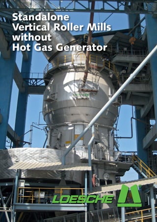
- 1. Standalone Vertical Roller Mills without Hot Gas Generator
- 2. OPTIMISED GRINDING I Standalone VRMs without HGG by Dr Daniel Strohmeyer, Water and energy are precious resources and without them life would not Loesche GmbH, Germany be as we know it today. Both commodities will become more expensive and scarcer in the future. Consequently, saving energy and water is essential for ecologically- and economically-viable production, particularly in the cement industry. F or vertical roller mills (VRM), water injection on the grinding table is a Figure 1: Loesche vertical roller mill for cement grinding common way to stabilise the grinding – material flow, feed materials and products bed and gives a smoother mill operation with lower vibration levels. However, there are some drawbacks to water use in a VRM. The feed moisture for OPC is commonly very low and in case water is added to the grinding process it has to be evaporated requiring thermal energy. If cooler exhaust gases are available in a cement plant this will not pose a major problem, but for a standalone grinding this source of hot gases is not available to drive-off any additional water. In this case a hot gas generator is needed to dry the material and to provide sufficient energy for the grinding system. This solution not only wastes fuel, it also creates further expenses. In some parts of the world the cement what is the centre of the rotating grinding the grinding table. Lumps, which escape industry is not permitted to utilise water table. The product is then driven outwards the rollers and are too heavy to rise with or its use is limited. Loesche has been by centrifugal forces, underneath the the gas flow drop through the louvre ring working on a system that can provide rollers where the grinding takes place. to a reject system and are then fed back grinding without the need for any water Ground material moves over the dam via the reject system. injection. Even if some water is available ring and goes up with the gas flow to the Raw mills or coal mills operate using the main aim is a grinding system that can classifier. The material has either reached the same size of rollers. What is particular be run without the need for permanent the required fineness and leaves the mill for Loesche cement mills is the 2+2 or operation of a hot gas generator. towards the bag filter or is sent back for 3+3 system, which features a combination further grinding, via the grid cone onto of different sizes of rollers. In cement VRMs A vertical roller mill can process many Figure 2: grinding plant flowsheet materials such as clinker, slag, gypsum, fly ash or limestone to produce various cement types of various finesse. The mill is part of a process that begins at the quarry. Only after the initial material has been through the raw material grinding, preheater, kiln and the cooler it reaches the finish mill where additives are added and the final product is obtained. Both Loesche and its customers are essentially concerned with this final product and its properties which are influenced by all stages of the cement making process. Material enters the VRM via a rotary feeder that poses as an air lock (see Figure 1), then moves down the feed chute to INTERNATIONAL CEMENT REVIEW JUNE 2011
- 3. OPTIMISED GRINDING Figure 3: assumed grindability for Ambuja Cement´s Dadri and Nalagarh projects A system fan provides the draft through the machine and different sources of hot gases can be utilized if required. Furthermore a wide range of feed materials are tolerated and conveyed to the mill via the feeding system. Ambuja Cement’s Dadri and Nalagarh grinding stations In 2007, Loesche received an enquiry for two grinding stations in India. Both would have a cement capacity of 1.6Mta and each would be supplied with a Loesche VRM with 250tph of grinding capacity. The Dadri project is situated near New Delhi and the Nalagarh mill mills, Loesche has a ‘S’ support roller and internal friction within the material layer is located further to the north, close to a ‘M’ master roller. The ‘S’ roller is solely making it difficult to efficiently apply the the Himalayas. It became apparent that to prepare and stabilise the grinding bed. grinding forces. So the ‘S’ roller removes the grinding stations would need to be The most difficult thing to achieve when the air from the grinding bed and operated without a hot gas generator producing cement is to keep the grinding prepares the material for the master roller and consequently water injection for bed stable. In comparison to raw material to carry out the grinding. the purpose of grinding bed stabilisation grinding, with cement milling there are The flowsheet for a grinding system was not permitted. Loesche looked at more fines and some parts of the grinding with a VRM (see Figure 2) shows that, the customer’s requirements before bed tend to become partly fluidised, after the classifier, product is precipitated deciding on the best solution. The main caused by entrapped air. This reduces the and then recovered from the bag filter. constituents to be ground were clinker, fly Ambuja Cement‘s grinding station Nalagarh, India JUNE 2011 INTERNATIONAL CEMENT REVIEW
- 4. OPTIMISED GRINDING OPTIMISED GRINDING Figure 3: assumed grindability for Ambuja Cement´s Dadri and Nalagarh projects A system fan provides the draft through Table 1: key data for Dadri and Nalagarh Table 2: Dadri performance different sources of the machine and data grinding stations hot gases can be utilized if required. Dadri Furthermore a wide range of feed PPC PPC capacity (tph) 250 LM 56.3+3 materials are tolerated and conveyed to Guarantee Achieved Gearbox power (kW) 5400 (Flender) the mill via the feeding system. Classifier LSKS 102 CS (kW) 560 Mill throughput (tph) 250 253 Fan motor power (kW) 3000 Fineness Ambuja Cement’s Dadri and 4000 3920 Mill diameter (m) 13.5 Feed moisture (%) Nalagarh grinding stations – 1.1 Height (m) 20 Product moisture (%) 2007, Loesche received an enquiry In – 0.3 Grinding table diameter (m) 5.6 Specific power consumption grinding stations in India. Both for two (kWh/t) 30.75 25.60 Grinding table weight (t) 109 (mill, fan, classifier, aux) have a cement capacity of 1.6Mta would Master roller (mm) 3 x2450 and each would be supplied with a Support roller (mm) 3 x 1600 Loesche VRM with 250tph of grinding capacity. The Dadri project is situated ash or clinker sources would be sourced. near New Delhi and had Nalagarh mill Therefore, Loesche the to assume a mills, and gypsum (up to five per cent) all ash Loesche has a ‘S’ support roller and internal friction within theto carry out a Standard procedure is material layer iscertain ‘grindability the north, close to located further to factor‘ and specific aof which have different‘S’ roller is solely ‘M’ master roller. The physical properties making it test to establish a proper sizing grinding difficult to efficiently apply the the Himalayas. It becamethe feed mix (see power consumption for apparent that to prepareleading to different grindabilities basically and stabilise the grinding bed. grinding mill andSo the ‘S’ box. However, for the forces. the gear roller removes the grinding stations would need to be Figure 3). The assumptions were based The most difficultindividualachieve when and a particular thing to behaviour the the from theboth of the projects it at air start of grinding bed and operated without a hot gas generator on Loesche’s experience and knowledge producing cement is to keep the grinding inside the mill. was not known where the different fly prepares the material for the master roller and other fly ash cement injection for of consequently water grinding plants bed stable. In comparison to raw material to carry out the grinding. the purpose of grinding bed concluded operating in India. Loesche stabilisation grinding, with cement milling there are The flowsheet for a grinding system was notwould need Loesche looked at that it permitted. a 56.3+3 mill with more fines and some parts of the grinding with a VRM (see Figure 2) shows that, thetable diameter of 5.6m. The selected a customer’s requirements before bed tend to become partly fluidised, after the classifier, product is precipitated deciding on the best solution. The main Flender gear box would have a power caused by entrapped air. This reduces the and then recovered from the bag filter. constituents toof 5400kW,were clinker, fly consumption be ground a Loesche dynamic classifier LSKS 102CS and a fan motor of 3000kW would form the other main parts of the system (see Table 1). Loesche’s scope of supply for the two Indian projects was not for the whole grinding plants, but for the mills, classifiers, sampling stations and the air slides for the product transport. Loesche’s product targets were PPC of 4000Blaine at 250tph using a specific power consumption of 30.75kWh/t for all the Loesche equipment and the fan supply Figure 4: erection of gear box (see Table 2). The PPC product would consist of 60 per cent clinker, five per cent gypsum and 35 per cent fly ash (2500 Blaine). If the plant receives clinker that is high in C3S then the fly ash content can be increased to the maximum permissible according to Indian standards. If the clinker exhibits a low C3S value, the plant can increase the clinker content and reduce the amount of fly ash to obtain the same required cement strength development. Construction of the mill foundation and the base frame. This is followed by the erection of the pedestals, which are a critical part of the construction phase as correct alignment is essential. The mill gear box is mounted by applying an orange ‘Chockfast’ (see Figure 4) which provides good connection of the gear box Figure 5: height of Loesche LM 56.3+3 when installed base plate and the foundation. The mill INTERNATIONAL CEMENT REVIEW JUNE 2011 JUNE 2011 INTERNATIONAL CEMENT REVIEW
- 5. OPTIMISED GRINDING OPTIMISED GRINDING housing is preassembled on the ground along with the classifier, before being lifted into place. The fly ash feeding system (see Figure 6) conveys design feeds dry fly ash directly to the classifier as part of the fly ash already has product fineness and does not need to be ground. Due to that, the capacity of the mill is increased. In the two Indian grinding stations, the fly ash is fed to the machine via two air slides. However, other setups allow for at least four inlets giving a more even distribution of the fly ash over the circumference of the classifier. Summary Loesche received the order for the two Figure 6: gypsum and fly ash feed system to the mill grinding systems in April 2007 and the FOB delivery was in November 2008. Figure 7: Nalagarh grinding plant Erection started in December 2008 and commissioning commenced in December 2009 with the first feed in February 2010. By April 2010, 250tph of PPC had been reached and in September 2010 further optimisation was done leading to a stable mill operation without any water injection for grinding bed stabilisation. As a result no hot gas generator was required. The specific power consumption achieved was 5kWh lower than expected. That was in part due to the easier-to-grind clinker and fly ash compared to the assumed values, both of which had an impact on the grindability of the feed mix and the related specific energy consumption. ______________________________ I LOESCHE Mill Type LM 56.3+3, Nalagarh, India Loesche GmbH Hansaallee 243 40549 Düsseldorf Tel. +49 - 211 - 53 53 - 0 Fax +49 - 211 - 53 53 - 500 E-Mail: loesche@loesche.de www.loesche.com JUNE 2011 INTERNATIONAL CEMENT REVIEW