
Recommended
More Related Content
What's hot
What's hot (11)
Viewers also liked
Viewers also liked (13)
Similar to Gas Diffusion through Thin Polystyrene Films
Similar to Gas Diffusion through Thin Polystyrene Films (20)
Gas Diffusion through Thin Polystyrene Films
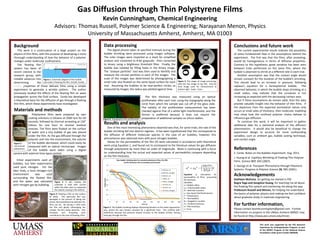
- 1. Gas Diffusion through Thin Polystyrene Films Kevin Cunningham, Chemical Engineering Advisors: Thomas Russell, Polymer Science & Engineering; Narayanan Menon, Physics University of Massachusetts Amherst, Amherst, MA 01003 Background Data processing Conclusions and future work This work is a continuation of a large project on the The digital photos taken at specified intervals during the The current experimental results indicate the possibility physics of thin films, with the purpose of developing a more bubble shrinking were processed using ImageJ software. of some fundamental flaw in the assumptions behind the thorough understanding of how the behavior of a polymer The color images were imported as a stack for simplified experiment. The first was that the films, after annealing, changes under molecular confinement. analysis and converted to 8-bit grayscale. then converted would be homogeneous in terms of diffusive properties. The floating film to binary using a brightness threshold filter. Finally, the Contrary to this hypothesis, great variation has been seen system has been of bubble was isolated by filling holes in the binary image. between trials performed on the same film, where the recent interest to the The “analyze particles” tool was then used to identify and bubble is observed to shrink at a different rate in each trial. research group, with measure the circular particles in each of the images. The Another assumption was that the contact angle would notable advances into Figure 1: Schematic diagram of the bubble scale of the images was determined by photographing a remain constant for the duration of the bubble’s shrinking. small ruler also floated on the same liquid surface for each Figure 5: The stages of image processing, determining the cast under a floating thin film. (Credit: Cerda) with the raw image at top left, and the This should lead to an increase in pressure, following elastic pr properties of these delicate films using a simple trial. Assuming the bubbles to be near-perfect circles, as final image used for measurement at Laplace’s equation for a hemispherical bubble. The experiment to generate a wrinkle pattern. The author measured by ImageJ, the radius was plotted against time. bottom right. Scale = 1mm. observed behavior, in which the bubble stops shrinking at a previously studied the effects of the floating film on wave small radius, may indicate that the curvature is not propagation across the fluid surface. Cerda has developed The film thickness was measured using an optical increasing as expected with the decreasing contact area. a theoretical basis for the diffusion of gas through a floating profilometer after each trial, using the topography along the But if these assumptions do remain valid, then the data thin film, which these experiments have investigated. circle from which the sample was cut off of the glass slide. provide valuable insight into the behavior of thin films. If The validity of the profilometer measurement has been the departure from the expected permeation values only Materials and methods checked against that of a white light interferometer, and the occurs at small vales of thickness, then molecular modeling Polystyrene films were prepared by spin former is preferred because it does not require the may show how the confined polymer chains behave to coating solutions in toluene at 2000 rpm for 60 Figure 6: Topography from profilometer. preparation of additional samples on silicon wafers. influence gas diffusion. seconds, followed by thermal annealing at 150° To continue this work, it will be important to gather Celsius for one hour to remove residual Results and analysis additional data for a statistical analysis of the diffusion stresses. The films were floated on the surface One of the most interesting phenomena observed was that, for some trials, the rate of the phenomenon. It would also be beneficial to change the of water and a tiny bubble of gas was placed bubble shrinking fell into distinct regimes. It has been hypothesized that this corresponds to experiment design to account for more confounding under the film. As the gas diffused through the the diffusion of different molecular species in the case of air bubbles; however, this variables, such as ambient gas, bubble casting technique, polymer and into the environment, the volume phenomenon was observed even with pure nitrogen bubbles. and contact angle. Figure 2: of the bubble decreased, which could easily be Values for the permeability of the film (P) were calculated in accordance with theoretical Commercial measured with an optical microscope. Images work using Equation 1, and found not to correspond to the literature values for gas diffusion polystyrene. of the bubble were taken using a digital through polystyrene by more than an order of magnitude. Work is continuing with a focus References camera with camerawith external time-lapse control. on understanding how the actual and expected values of permeability compare depending E. Cerda. Notes on the Bubbles Experiment. Aug. 2011. on the film thickness. J. Huang et al. Capillary Wrinkling of Floating Thin Polymer Initial experiments used air Raw bubble shrinking data for annealed polystyrene films, Mn=99k Films. Science 317, 650 (2007). by film thickness and surrounding environment bubbles, but later experiments 1.4 used pure nitrogen. For the S. George et al. Transport Phenomena through Polymeric later trials, a local nitrogen-rich 1.2 49.5nm, air Systems. Progress in Polymer Science 26, 985 (2001). 49.5nm, nitrogen environment was used 1 49.5nm, air Equation 1: Calculation permeability of films, accounting for Acknowledgements surrounding the floated film, 58nm, air Kathleen McEnnis, for getting me started in PSE Radius (mm) 0.8 for thickness. and the water was saturated Figure 3: In spin coating, the 58nm, nitrogen Variables: Bugra Toga and Jiangshui Huang, for teaching me all about with nitrogen gas by bubbling. substrate is held with suction 0.6 67.4nm, air a = Bubble radius while the plate spins to evaporate 67.4nm, air a0 = Initial bubble radius the floating film system and mentoring me along the way the solvent, leaving a film behind. 0.4 67.4nm, nitrogen R = Ideal Gas constant Professors Russell and Menon, for helping me understand Figure 4: Floating a film on the surface γ = Gas-liquid interfacial tension the basics of polymer physics and making me feel confident 0.2 of water. This particular film was T = Temperature P = Permeability about graduate study in materials engineering damaged in the process of taking the 0 photo, demonstrating how delicate thin 0 20 40 60 80 100 120 140 160 180 200 N = Avogadro’s number films can be. By tracing a circle onto the film and gently submerging the Time (s) Figure 7: The bubble shrinking displays interesting behavior as the radius approaches P0 = Ambient pressure h = Film thickness For further information, sample, the film easily detaches. Film zero, where the size remains constant for a significant time. This conflicts with t = Time Please contact kevinhcunningham@gmail.com. Further thickness and annealing time predictions because the pressure should increase as the bubble shrinks, forcing information on projects in the UMass Amherst MRSEC may contribute to the ease of floating a film. more gas through the film. be found at http://www.pse.umass.edu/mrsec. This work was supported by the PSE Research Experience for Undergraduates Program, as part of the MRSEC Program of the National Science Foundation under grant number 0820506.