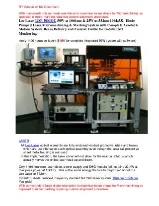
Dana Lee Church = Lee Laser 532nm Micromachining System r8

Completely integrated Lee Laser LDP-50MQG 50W at 1064nm & 25W at 532nm 1064/532 Diode Pumped Laser Micromachining & Marking System with Complete Aerotech Motion System, Beam Delivery and Coaxial Visible for In-Situ Part Monitoring. This is a great but very simple micromachining system which can be switched from 1064 to 532. Modularized fixtures were designed and fabricated in our machine shop for this system. We have in-situ measurement capability so you do not have to take your part off of the system in order to measure it when you are developing a recipe for a new machining process. I wrote all software, embedded, GUI, motion control code, etc. The visible imaging could be improved upon but I believe it has a lot more to do with light and illumination than anything else. Also, as I saw once I sold a system like this, not everyone understands that the focusing optic has to pass the VISIBLE spectrum as well as 532nm. If it does not then the combined visible and laser wavelength beam paths cannot be mated and there will be no clear visible image on the display monitor or through the frame grabber. Seems like common sense to me but......well I also saw a Ph.D. install a vertical, standalone PC upside down next to their desk and wonder why they couldn't keep the DVDs from falling to the floor.....:)

Recommended
More Related Content
More from Dana Lee Church
Recently uploaded
Recently uploaded (20)
Dana Lee Church = Lee Laser 532nm Micromachining System r8
- 1. Lee Laser LDP-50MQG 50W at 1064nm & 25W at 532nm 1064/532 Diode Pumped Laser Micromachining & Marking System with Complete Aerotech Motion System, Beam Delivery and Coaxial Visible for In-Situ Part Monitoring. (only 1490 hours on laser) ($45K for complete integrated 50W system with software) LASER All Lee Laser optical elements are fully enclosed via dust protective tubes and hoses which are used between each optical assembly even though the laser rail protective sheet metal housing is not used. In this implementation, the laser cover will not allow for the manual Z focus which actually moves the entire laser head up and down. Only 1490 hours on laser diode, power supply and SHG module (still obtains 22.4W at max peak power at 10kHz). This is the same energy that we had upon receipt of the Lee Laser at 532nm. Q-Switch, diode pumped, frequency doubled Nd:YAG laser system. 1064nm or 532nm. You pick! With non-standard laser diode orientation to maximize beam shape for Micromachining as opposed to micro marking requiring custom alignment procedure. With non-standard laser diode orientation to maximize beam shape for Micromachining as opposed to micro marking requiring custom alignment procedure. R7 Version of this Document.
- 2. The laser has been aligned specifically for laser micromachining of holes and channels. This means that the beam was not aligned for best power which has the tendency to create a multimodal beam where the energy is stretched among a larger output circle (aperture). When aligned for best Gaussian, this laser can produce a fully round spot as low as 12 ums at the work surface. Our best laser technician is able to achieve this alignment through our special techniques. If aligned as taught at Lee Laser, then the laser will achieve best power however the beam may become multimodal and then is not ideal for micromachining holes but is perfectly fine for micro marking applications. The laser was aligned using custom alignment tools which come with the system. When the beam is viewed in the far field ~5 meters, it must still be round and as close to Gaussian as possible. When reordering a Q-Switch be sure that the following is observed: The two LDP-50MQG lasers each use a 3 mm X 70 mm Nd: YAG rod. The SHG Modules each contain 5 X 5 mm LBO crystals. Complete report of current status of laser energy output as a function of current input is below and updated on August 1st , 2011. Taken at 10 kHz. Optimized for best beam We purchased a modified diode module that is perpendicularly oriented which is VERY DIFFERENT than the commonly delivered modules which provided a NON-multimodal beam and REQUIRES a different laser alignment procedure than that ordinarily used for Lee Lasers. We specified and ordered this custom diode module in order to provide a more round beam shape when properly aligned. If a typical (non-TeoSys) alignment is performed such as how Lee Laser normally teaches, the beam will be multimodal and will NOT OPERATE PROPERLY!!! The TeoSys alignment procedure is defined in the LMS5000 Systems Manual in great detail. If changing the laser diode, the correct diode orientation must be purchased for optimum performance. This diode costs slightly more than the one which is normally shipped (99%) with the Lee Laser LDP-50MQG. R7 Version of this Document.
- 3. quality not maximum power. There are differing ways to align these lasers and we have always gone for best roundness and even energy across the beam. Material suitability for laser processing using this laser: Along with purchase of a non-standard laser diode orientation to maximize beam spot roundness. R7 Version of this Document.
- 5. Aerotech Complete Integrated MOTION SYSTEM Two (2) Aerotech ALS3600 linear motor stages with 12” of travel. Parameter file included or U500 PCI Ultra Card with PSO (Pulsed Synchronized Output in both X and Y axes). Of course these stages can also be run via Aerotech’s new Ndrive and Npaq and A3200 solutions. The demand for a high-accuracy, robust, open-frame stage is met with the ALS3600. This dual-axis, large aperture, open-frame stage addresses the needs of scanning microscopy, wafer and printed circuit board inspection, and automated assembly. We use the large format primary to hold other larger rotary stages or to machine large substrates. Stages have a large clear aperture: As can be seen by the picture below, the stages have a clear aperture when the TeoSys-made adapter plate is not installed. The adapter plate allows us to install many different types of fixtures on the system. The large format of these linear stages allows for our installation of the Aerotech ART320 rotary stage (OPTIONAL) in addition to the numerous general purpose fixtures. The adapter plate allowing a rotary stage or other stage to be attached on top of the X & Y stages IS INCLUDED. R7 Version of this Document.
- 6. Travel range for these stages is X=300 mm by Y= 300 mm (12 “ x 12”). Stage Dimensions:
- 8. High performance linear motion guides: Aerotech linear motors are direct drive and consist of a noncontact-ting forcer coil and “U-channel” or “flat” rare-earth magnet track. This design eliminates backlash, windup, wear, and maintenance issues associated with ball screw, belt, and rack and pinion based motion control and positioning systems. The noncontact design of the forcer and magnet track results in a maintenance-free system. The ALS3600 utilizes high-precision linear motion guide (LMG) bearings, with a total of four trucks per axis. These make the ALS3600 ideal for fast, repetitive operations. The LMG bearings also exhibit exceptional stiffness, high load capacity, and extremely low friction. 15 arc sec orthogonality Brushless Linear Servomotor (Linear Brushless Servomotor (BLMFI-142-A)) The ALS3600 incorporates a high power linear motor to meet the needs of the most demanding applications. This results in a stage with all of the advantages of a direct- drive mechanism: zero backlash, no windup, exceptional acceleration, zero friction, and outstanding servo stiffness. Many applications require extreme stability of motion that can only be met with a linear motor drive. Since the drive train has zero friction and no recirculating elements, the ALS3600 is ideal for scanning, imaging, and many other precision applications. High-Accuracy Linear Encoder Feedback The standard feedback device is a high-resolution, noncontact linear encoder. This noncontact encoder offers exceptional repeatability and stability over a range of operating conditions. Both digital and analog output versions are available. The digital version has a resolution of 1 µm, while the analog version, when coupled with an Aerotech multiplier box, can reach resolutions of 20 nm. Maximum Travel Speed is 300 mm/s (12 in/s) Maximum Linear Acceleration is 1 g (10 m/s2 ) (386 in/s2 ) (No Load) Maximum Load is 90.0 kg (198.4 lb) Accuracy is ±12.0 µm (±480 µin) Repeatability is ±1.0 µm (±40 µin) Straightness and flatness differential is 1.0 µm/25 mm (40 µin/in) Straightness and flatness maximum deviation is ±6.0 µm (±240 µin) Pitch and Yaw is 18 arc sec Nominal Stage Weight is 58.0 kg (127.9 lb) Moving Mass (Lower X Axis) is 40.1 kg (88.5 lb) Moving Mass ( Upper Y Axis) is 13.6 kg (30 lb) Construction is Aluminum Body/Black Anodize Finish/Hardcoat
- 9. ART320 Rotary Positioning Gear Drive Stage (OPTIONAL) One (1) Optional Aerotech ART320 rotary stage with BM75 Motor capable of running via an AS32020 amplifier with at least 40V bus on a DR500 or run it totally independently using one of Aerotech’s new NDrive. Continuous 360° rotary positioning Precision worm gear drive for outstanding accuracy and repeatability The BM series of motors consists of Aerotech’s high-performance brushless rotary servomotors. The motors feature neodymium iron boron magnets for maximum torque and acceleration in a small package. A skewed stator design and an eight-pole rotor provide low torque ripple and smooth velocity. The BM series motors can reach speeds up to 10,000 rpm and accelerations to 270,000 rad/s2 for improved machine cycle times. Unlike DC brush-type servomotors, the BM series are brushless and maintenance free. This makes them ideal for critical applications where downtime cannot be tolerated. In addition, the BM series motors have very high power density resulting in high torque in a compact package. Optional IP65 sealing make these motors ideal for harsh environments such as machine tool. BM75 High Torque Motor in NEMA Case
- 10. High-Performance Design The BM series of motors consists of Aerotech’s high-performance brushless rotary servomotors. The motors feature neodymium iron boron magnets for maximum torque and acceleration in a small package. A skewed stator design and an eight-pole rotor provide low torque ripple and smooth velocity. The BM series motors can reach speeds up to 10,000 rpm and accelerations to 270,000 rad/s2 for improved machine cycle times. Unlike DC brush-type servomotors, the BM series are brushless and maintenance free. This makes them ideal for critical applications where downtime cannot be tolerated. In addition, the BM series motors have very high power density resulting in high torque in a compact package. Optional IP65 sealing make these motors ideal for harsh environments such as machine tool. Wide Torque Range The BM motor series covers a wide range of torque and package sizes. Continuous output torque ranges from 0.16 N-m (22.5 oz-in) to 31.6 N-m (280 lb-in), with peak torques to 94.9 N-m (840 lb-in). Standard frame sizes include NEMA 17, 23, 34, 42, and IEC 142. This makes it easy to mount any motor to Aerotech’s gearbox line with no adapter plates. These motors are well-suited to general purpose and high-end servo applications. Application Flexibility The standard motor and the one that comes with the ART320 rotary stage has a 1000- line encoder (4000-line count after quadrature), RS-422 line driver output with Hall effect device outputs for commutation, and MS connectors. Stall Torque, Continuous - 0.55 N m or 78.3 oz inches Peak Torque - 1.4 N-m or 196 oz-inches Rated Speed - 4000 RPM Rated Power Output - Continuous is 207 Watts BEMF Constant (Line-Line, Max) - 9 Voltspk/krpm Continuous Current, Stall - 7.1 Amprms Peak Current, Stall - 25 Amppk, 17.7 Amprms Torque Constant - 0.06 N-m/Amppk, 7.8 oz-in/Amppk, 0.08 N-m/Amprms, 11.1 oz-in/Amprms Motor Constant - 0.052 N-m/√W, 7.33 oz-in/√W Resistance, 25°C (Line-Line) – 1.0 ohms Inductance (Line-Line) - 0.80 mH Maximum Bus Voltage – 340 VDC Thermal Resistance – 1.14 C/W Number of Poles – 8 P Encoder Options – Quadrature Motor Weight – 2.42 lb Rotor Moment of Inertia – 0.0007 oz-in-s2
- 11. Max Radial Load – 20 lb Max Axial Load – 80 lbs Aerotech DR500 Motion Controller with PCI based PSO (Pulsed Synchromized Output) Motion Controller Legacy Aerotech DR 300 40W amplifier rack with 4 AS32020 amplifiers Aerotech's DR300/DR500/DR600/DR800 drive racks may also be upgraded via the Nservo or the Npaq drive rack so that the system may be upgraded to Aerotech’s A3200 embedded controller or one could also specify the system components themselves via the other options of Ndrive for fully connected, Ensemble for a standalone version which runs much like a microcontroller in that you download your code and it runs on its own with no communication to a main controller or NSoloist. . The legacy PC with Aerotech U500 Ultra w/PSO (pulse synchronized output) PSO allows for a trigger pulse to exit from the U500 controller board based on the exact movement of either the X or the Y stage or both combined. This function is imperative for laser marking and makes laser drilling much easier when using a pulsed laser. The system is currently configured to control the frequency of the 532nm laser (4kHz – 30kHz) via this output line.
- 12. Aerotech now has a program called CADFusion which bridges the gap between part drawing and Aerotech G Code making the reliance on low level G code programming a legacy operation.
- 13. BEAM DELIVERY (Both visible and laser) IO already wired for laser control & operator input via joystick, buttons and switches. Programmable via Aerotech MMI (RS 274 G-Code) or Visual Basic (already on the PC, or LabView (not on PC). Beam Delivery System is in the above picture with integrated camera and live video frame grabber and all associated software is on the Intel based Win2K PC. (coaxial visible via the camera and 532/1064 wavelengths) and a single turning mirror for maximum power at the work surface. Focusing lens varies depending upon the application but the mount is for 1” or 25mm focusing optics. The integrated camera allows viewing of the work surface during machining. This camera may also be calibrated to the application’s field of view at any time using the Measurement software which comes with system and is described below. This allows for the direct measurement of the machined feature without having to take it to an external microscope. This feature of the system is included via a software measurement program which can be easily calibrated via the motion system or via a stage calibration slide. One calibration slide will come with the system. All source code comes with the system. Output from laser Turning mirror for 532nm and beam combiner Focusing optics (in this picture it is a 1” Thorlabs tube holding a 50mm PLCC optic from Edmunds Camera Camera visible optical path Visible beam path 532nm beam path
- 14. Software and its Measurement Capbilities The software below is measurement software which can be integrated and calibrated once a beam delivery and focusing optic has been chosen. At this time, the visible can be aligned with the wavelength and any view captured via the camera can be input into this measurement software for in-situ measuring of features. The quality and accuracy of the live video image is totally dependent upon the visible optical setup chosen. NOTE: This type of picture and its resolution depends wholly on the quality of the visible path alignment and lighting conditions. This is video microscope software so it has all of the requirements that pertain to quality measurement systems. Example of measuring software. Measurement software has four independent horizontal and four independent vertical measurement calipers which can be used to measure features once the visible beam path is calibrated to the laser beam path (or drilling path in the case of a MicroMill).
- 15. The above picture shows 50 micron holes drilled through polyurethane film without burn or edge degredation. We struggled to go with larger holes than 200 um with the 532nm wavelength. Then we would choose a faster wavelength and shorter pulse duration. The above is a picture of a 150 micron hole drilled through a silicone tube. The measurement software was used to grab pictures of each and every part in-situ for 100% inspection. FIXTURES Measurement output data which cannot be seen in the photo due to resolution of my picture of the actual photo. Measurement output data which CAN be seen in the photo.
- 16. The system comes with all sorts of holding fixtures including slide holders, flat fixtures, tube holding fixture via a keyless chuck with through hole, semiconductor plate 8” holder, an 8 position rotating fixture for multiple simultaneous operations while drilling (see picture below), etc.. ART320 with adapter plate on Illuminator knobs. Joysticks to control up to four stages via the Aerotech U500 MMI software package which is similar to an HMI. Buttons which can be programmed to do anything There is also one foot switch which is also capable of being programmed to do anything. We used it to turn the plate to the next index position. This is the plate where we held the parts. The plate does not come with the system but another could easily be made This is the magnet which we used to catch the parts when they came around. We made sure that the index plate was made of a non‐ magnetic material so the rare earth magnet in the fixture would pull the parts right off. Beam delivery turning and visible/laser combining mirror. Beam expander 2X thru 8X
- 17. NOTE: This fixture is on another machine as all of our fixtures were interchangeable. And there are the very important rotary fixtures of which there are many. Most would be based on our OPTIONAL ART320 but not all.
- 18. Above: Stainless steel cutting using the 532nm laser using the above fixture. Above: 300 micron stainless steel filter cloth disks cut using 532nm laser using a flat fixture but there was incredible loss due to transferring 300um discs to travel packaging.
- 19. Includes full In-Situ measurement software which runs on the integrated frame grabber. Allows for NIST traceable measurement of parts under inspection without removal from the system as seen above. Manual Z axis focus which actually moves the entire laser head up and down. This design can be changed. 532 Beam expander (Roddenstock). Lee Laser’s Model LBX-2/8 Adjustable Ratio. Expansion can be adjusted continuously from 2X to 8X. This permits change of beam focus spot diameter at the work piece without vertical change of the location of the focal point. HeNe alignment tool (no longer integrated) but came with laser rail. It can be reinstalled or for protection shipped separately. Complete set of replacement filters for pump, carbon filters and UV light for integrated laser water cooling Extra Wiring and Integration of User Interface with Motion and Laser The system also has 2 integrated joysticks already set up for controlling the stages. There are an additional 2 buttons pre-wired into the Aerotech controller inputs which can be used in any motion control program. Inputs 0 and 1. The system also has four dials which are usually connected to various light sources depending upon the application. The dials allow varying the light intensity..
- 20. OPTIONAL (Recommended Only for the 25W 1064nm / 10W 532nm Smaller format laser) (Complete Galvo Laser System $18k) Galvo or Scanning Operation as opposed to Direct Write use of the smaller system. One (1) Optional ScanLab Galvo for 1064nm and 1 for 532nm with a 3” f-theta lens are optionally available for the either the 50W or the 25W lasers. We have another set of two (2) Optional Scan heads which run in 532nm mode but one of the mirrors is broken in just one of the scan heads. Just that one mirror would need replacing. The other scan head has both mirrors. Although I would probably recommend replacing the mirrors in both of the 532nm Scan heads as they are well used. To switch from direct write using the Aerotech Stages to the Galvo just a few screws need to be undone to remove the beam delivery plate from the end of the Lee Laser rail. Then the galvo is screwed into the adapter plate that we made for the system. We only have one adapter plate which was generally used for the 25W (the less powerful system and we ran it in 1064nm mode so we could use it mostly for marking). There is a separate Optional cable for the Optional RTC3 card. The RTC3 card resides in a computer which is attached to the Lee Laser power supply in order to control the firing. Again, this option is meant for our smaller version of the 1064 Nd: YAG 25W instead of our 50W system which we used mostly in direct write mode. We have a working cable for an RTC3 card to the Lee Laser power supply for the 1064 25W system. The Optional Prolase and its license would come with the ScanLab Galvo Intelliscan version. Prolase is great at laser marking. There is now the IntelliDrill version. It would be best just to purchase the lower power Lee Laser system already set up with the Galvo Option rather than try to merge the Option galvo to the 50W 1064nm Nd:YAG offered in this proposal.