CCS355 Neural Network & Deep Learning Unit II Notes with Question bank .pdf
Solução mecânica vetorial para engenheiros.
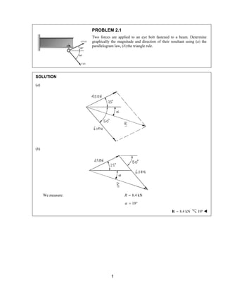
1. PROBLEM 2.1
Two forces are applied to an eye bolt fastened to a beam. Determine
graphically the magnitude and direction of their resultant using (a) the
parallelogram law, (b) the triangle rule.
SOLUTION
(a)
(b)
We measure: R = 8.4 kN
α = 19°
R = 8.4 kN 19°W
1
2. PROBLEM 2.2
The cable stays AB and AD help support pole AC. Knowing that the
tension is 500 N in AB and 160 N in AD, determine graphically the
magnitude and direction of the resultant of the forces exerted by the stays
at A using (a) the parallelogram law, (b) the triangle rule.
SOLUTION
We measure: α = 51.3°, β = 59°
(a)
(b)
We measure: R = 575 N,α = 67°
R = 575 N 67°W
2
3. PROBLEM 2.3
Two forces P and Q are applied as shown at point A of a hook support.
Knowing that P = 15 lb and Q = 25 lb, determine graphically the
magnitude and direction of their resultant using (a) the parallelogram law,
(b) the triangle rule.
SOLUTION
(a)
(b)
We measure: R = 37 lb,α = 76°
R = 37 lb 76°W
3
4. PROBLEM 2.4
Two forces P and Q are applied as shown at point A of a hook support.
Knowing that P = 45 lb and Q = 15 lb, determine graphically the
magnitude and direction of their resultant using (a) the parallelogram law,
(b) the triangle rule.
SOLUTION
(a)
(b)
We measure: R = 61.5 lb,α = 86.5°
R = 61.5 lb 86.5°W
4
5. PROBLEM 2.5
Two control rods are attached at A to lever AB. Using trigonometry and
knowing that the force in the left-hand rod is F1 = 120 N, determine
(a) the required force F2 in the right-hand rod if the resultant R of the
forces exerted by the rods on the lever is to be vertical, (b) the
corresponding magnitude of R.
SOLUTION
Graphically, by the triangle law
We measure: F2 ≅ 108 N
R ≅ 77 N
By trigonometry: Law of Sines
F R
α β
2 = =
120
sin sin 38 °
sin
α = 90° − 28° = 62°, β = 180° − 62° − 38° = 80°
Then:
F = R =
2 120 N
sin 62 sin 38 sin80
° ° °
or (a) F2 = 107.6 N W
(b) R = 75.0 NW
5
6. PROBLEM 2.6
Two control rods are attached at A to lever AB. Using trigonometry and
knowing that the force in the right-hand rod is F2 = 80 N, determine
(a) the required force F1 in the left-hand rod if the resultant R of the
forces exerted by the rods on the lever is to be vertical, (b) the
corresponding magnitude of R.
SOLUTION
Using the Law of Sines
F R
α β
1 = =
80
sin sin 38 °
sin
α = 90° − 10° = 80°, β = 180° − 80° − 38° = 62°
Then:
F = R =
1 80 N
sin80 sin 38 sin 62
° ° °
or (a) F1 = 89.2 N W
(b) R = 55.8 N W
6
7. PROBLEM 2.7
The 50-lb force is to be resolved into components along lines a-a′ and
b-b′. (a) Using trigonometry, determine the angle α knowing that the
component along a-a′ is 35 lb. (b) What is the corresponding value of
the component along b-b′?
SOLUTION
Using the triangle rule and the Law of Sines
(a) sin sin 40
β °
=
35 lb 50 lb
sinβ = 0.44995
β = 26.74°
Then: α + β + 40° = 180°
α = 113.3°W
(b) Using the Law of Sines:
50 lb
Fbb
α
′ =
sin sin 40
°
Fbb′ = 71.5 lb W
7
8. PROBLEM 2.8
The 50-lb force is to be resolved into components along lines a-a′ and
b-b′. (a) Using trigonometry, determine the angle α knowing that the
component along b-b′ is 30 lb. (b) What is the corresponding value of
the component along a-a′?
SOLUTION
Using the triangle rule and the Law of Sines
(a) sin sin 40
α °
=
30 lb 50 lb
sinα = 0.3857
α = 22.7°W
(b) α + β + 40° = 180°
β = 117.31°
50 lb
Faa
β
′ =
sin sin 40
°
50 lb sin
β
Faa
′
= sin 40
° Faa′ = 69.1 lbW
8
9. PROBLEM 2.9
To steady a sign as it is being lowered, two cables are attached to the sign
at A. Using trigonometry and knowing that α = 25°, determine (a) the
required magnitude of the force P if the resultant R of the two forces
applied at A is to be vertical, (b) the corresponding magnitude of R.
SOLUTION
Using the triangle rule and the Law of Sines
Have: α = 180° − (35° + 25°)
= 120°
P = R =
Then: 360 N
sin 35 sin120 sin 25
° ° °
or (a) P = 489 N W
(b) R = 738 NW
9
10. PROBLEM 2.10
To steady a sign as it is being lowered, two cables are attached to the sign
at A. Using trigonometry and knowing that the magnitude of P is 300 N,
determine (a) the required angle α if the resultant R of the two forces
applied at A is to be vertical, (b) the corresponding magnitude of R.
SOLUTION
Using the triangle rule and the Law of Sines
(a) Have: 360 N =
300 N
sinα sin 35
°
sinα = 0.68829
α = 43.5°W
(b) β = 180 − (35° + 43.5°)
= 101.5°
R =
Then: 300 N
sin101.5 sin 35
° °
or R = 513 NW
10
11. PROBLEM 2.11
Two forces are applied as shown to a hook support. Using trigonometry
and knowing that the magnitude of P is 14 lb, determine (a) the required
angle α if the resultant R of the two forces applied to the support is to be
horizontal, (b) the corresponding magnitude of R.
SOLUTION
Using the triangle rule and the Law of Sines
(a) Have: 20 lb =
14 lb
sinα sin 30
°
sinα = 0.71428
α = 45.6°W
(b) β = 180° − (30° + 45.6°)
= 104.4°
R =
Then: 14 lb
sin104.4 sin 30
° °
R = 27.1 lbW
11
12. PROBLEM 2.12
For the hook support of Problem 2.3, using trigonometry and knowing
that the magnitude of P is 25 lb, determine (a) the required magnitude of
the force Q if the resultant R of the two forces applied at A is to be
vertical, (b) the corresponding magnitude of R.
Problem 2.3: Two forces P and Q are applied as shown at point A of a
hook support. Knowing that P = 15 lb and Q = 25 lb, determine
graphically the magnitude and direction of their resultant using (a) the
parallelogram law, (b) the triangle rule.
SOLUTION
Using the triangle rule and the Law of Sines
Q =
(a) Have: 25 lb
sin15 sin 30
° °
Q = 12.94 lbW
(b) β = 180° − (15° + 30°)
= 135°
R =
Thus: 25 lb
sin135 sin 30
° °
25 lb sin135 35.36 lb
R ° = = sin 30
°
R = 35.4 lbW
12
13. PROBLEM 2.13
For the hook support of Problem 2.11, determine, using trigonometry,
(a) the magnitude and direction of the smallest force P for which the
resultant R of the two forces applied to the support is horizontal,
(b) the corresponding magnitude of R.
Problem 2.11: Two forces are applied as shown to a hook support. Using
trigonometry and knowing that the magnitude of P is 14 lb, determine
(a) the required angle α if the resultant R of the two forces applied to the
support is to be horizontal, (b) the corresponding magnitude of R.
SOLUTION
(a) The smallest force P will be perpendicular to R, that is, vertical
P = (20 lb)sin 30°
= 10 lb P = 10 lb W
(b) R = (20 lb)cos30°
= 17.32 lb R = 17.32 lbW
13
14. PROBLEM 2.14
As shown in Figure P2.9, two cables are attached to a sign at A to steady
the sign as it is being lowered. Using trigonometry, determine (a) the
magnitude and direction of the smallest force P for which the resultant R
of the two forces applied at A is vertical, (b) the corresponding magnitude
of R.
SOLUTION
We observe that force P is minimum when α is 90°, that is, P is horizontal
Then: (a) P = (360 N)sin 35°
or P = 206 N W
And: (b) R = (360 N)cos35°
or R = 295 NW
14
15. PROBLEM 2.15
For the hook support of Problem 2.11, determine, using trigonometry, the
magnitude and direction of the resultant of the two forces applied to the
support knowing that P = 10 lb and α = 40°.
Problem 2.11: Two forces are applied as shown to a hook support. Using
trigonometry and knowing that the magnitude of P is 14 lb, determine
(a) the required angle α if the resultant R of the two forces applied to the
support is to be horizontal, (b) the corresponding magnitude of R.
SOLUTION
Using the force triangle and the Law of Cosines
R2 = (10 lb)2 + (20 lb)2 − 2(10 lb)(20 lb)cos110°
= 100 + 400 − 400(−0.342) lb2
= 636.8 lb2
R = 25.23 lb
Using now the Law of Sines
10 lb =
25.23 lb
sinβ sin110
°
sin 10 lb sin110
β = °
25.23 lb
= 0.3724
So: β = 21.87°
Angle of inclination of R, φ is then such that:
φ + β = 30°
φ = 8.13°
Hence: R = 25.2 lb 8.13°W
15
16. PROBLEM 2.16
Solve Problem 2.1 using trigonometry
Problem 2.1: Two forces are applied to an eye bolt fastened to a beam.
Determine graphically the magnitude and direction of their resultant
using (a) the parallelogram law, (b) the triangle rule.
SOLUTION
Using the force triangle, the Law of Cosines and the Law of Sines
We have: α = 180° − (50° + 25°)
= 105°
Then: R2 = (4.5 kN)2 + (6 kN)2 − 2(4.5 kN)(6 kN)cos105°
= 70.226 kN2
or R = 8.3801 kN
Now: 8.3801 kN =
6 kN
sin105 °
sin β
sin 6 kN sin105
β = °
8.3801 kN
= 0.6916
β = 43.756°
R = 8.38 kN 18.76°W
16
17. PROBLEM 2.17
Solve Problem 2.2 using trigonometry
Problem 2.2: The cable stays AB and AD help support pole AC. Knowing
that the tension is 500 N in AB and 160 N in AD, determine graphically
the magnitude and direction of the resultant of the forces exerted by the
stays at A using (a) the parallelogram law, (b) the triangle rule.
SOLUTION
From the geometry of the problem:
tan 1 2 38.66
α = − = °
2.5
tan 1 1.5 30.96
β = − = °
2.5
Now: θ = 180° − (38.66 + 30.96°) = 110.38
And, using the Law of Cosines:
R2 = (500 N)2 + (160 N)2 − 2(500 N)(160 N)cos110.38°
= 331319 N2
R = 575.6 N
Using the Law of Sines:
160 N =
575.6 N
sinγ sin110.38
°
sin 160 N sin110.38
γ = °
575.6 N
= 0.2606
γ = 15.1°
φ = (90° −α ) + γ = 66.44°
R = 576 N 66.4°W
17
18. PROBLEM 2.18
Solve Problem 2.3 using trigonometry
Problem 2.3: Two forces P and Q are applied as shown at point A of a
hook support. Knowing that P = 15 lb and Q = 25 lb, determine
graphically the magnitude and direction of their resultant using (a) the
parallelogram law, (b) the triangle rule.
SOLUTION
Using the force triangle and the Laws of Cosines and Sines
We have:
γ = 180° − (15° + 30°)
= 135°
Then: R2 = (15 lb)2 + (25 lb)2 − 2(15 lb)(25 lb)cos135°
= 1380.3 lb2
or R = 37.15 lb
and
25 lb =
37.15 lb
sinβ sin135
°
sin 25 lb sin135
β = °
37.15 lb
= 0.4758
β = 28.41°
Then: α + β + 75° = 180°
α = 76.59°
R = 37.2 lb 76.6°W
18
19. PROBLEM 2.19
Two structural members A and B are bolted to a bracket as shown.
Knowing that both members are in compression and that the force is
30 kN in member A and 20 kN in member B, determine, using
trigonometry, the magnitude and direction of the resultant of the forces
applied to the bracket by members A and B.
SOLUTION
Using the force triangle and the Laws of Cosines and Sines
We have: γ = 180° − (45° + 25°) = 110°
Then: R2 = (30 kN)2 + (20 kN)2 − 2(30 kN)(20 kN)cos110°
= 1710.4 kN2
R = 41.357 kN
and
20 kN =
41.357 kN
sinα sin110
°
sin 20 kN sin110
α = °
41.357 kN
= 0.4544
α = 27.028°
Hence: φ = α + 45° = 72.028°
R = 41.4 kN 72.0°W
19
20. PROBLEM 2.20
Two structural members A and B are bolted to a bracket as shown.
Knowing that both members are in compression and that the force is
20 kN in member A and 30 kN in member B, determine, using
trigonometry, the magnitude and direction of the resultant of the forces
applied to the bracket by members A and B.
SOLUTION
Using the force triangle and the Laws of Cosines and Sines
We have: γ = 180° − (45° + 25°) = 110°
Then: R2 = (30 kN)2 + (20 kN)2 − 2(30 kN)(20 kN)cos110°
= 1710.4 kN2
R = 41.357 kN
and
30 kN =
41.357 kN
sinα sin110
°
sin 30 kN sin110
α = °
41.357 kN
= 0.6816
α = 42.97°
Finally: φ = α + 45° = 87.97°
R = 41.4 kN 88.0°W
20
21. PROBLEM 2.21
Determine the x and y components of each of the forces shown.
SOLUTION
20 kN Force:
Fx = +(20 kN)cos 40°, Fx = 15.32 kN W
Fy = +(20 kN)sin 40°, Fy = 12.86 kNW
30 kN Force:
Fx = −(30 kN)cos70°, Fx = −10.26 kN W
Fy = +(30 kN)sin 70°, Fy = 28.2 kNW
42 kN Force:
Fx = −(42 kN)cos 20°, Fx = −39.5 kNW
Fy = +(42 kN)sin 20°, Fy = 14.36 kNW
21
22. PROBLEM 2.22
Determine the x and y components of each of the forces shown.
SOLUTION
40 lb Force:
Fx = −(40 lb)sin 50°, Fx = −30.6 lbW
Fy = −(40 lb)cos50°, Fy = −25.7 lbW
60 lb Force:
Fx = +(60 lb)cos60°, Fx = 30.0 lbW
Fy = −(60 lb)sin 60°, Fy = −52.0 lbW
80 lb Force:
Fx = +(80 lb)cos 25°, Fx = 72.5 lbW
Fy = +(80 lb)sin 25°, Fy = 33.8 lb W
22
23. PROBLEM 2.23
Determine the x and y components of each of the forces shown.
SOLUTION
We compute the following distances:
2 2
( ) ( )
( ) ( )
( ) ( )
48 90 102 in.
56 2 90 2
106 in.
80 2 60 2
100 in.
OA
OB
OC
= + =
= + =
= + =
Then:
204 lb Force:
(102 lb) 48 ,
x 102 F = − Fx = −48.0 lbW
(102 lb) 90 ,
y 102 F = + Fy = 90.0 lb W
212 lb Force:
(212 lb) 56 ,
x 106 F = + Fx = 112.0 lbW
(212 lb) 90 ,
y 106 F = + Fy = 180.0 lbW
400 lb Force:
(400 lb) 80 ,
x 100 F = − Fx = −320 lb W
(400 lb) 60 ,
y 100 F = − Fy = −240 lbW
23
24. PROBLEM 2.24
Determine the x and y components of each of the forces shown.
SOLUTION
We compute the following distances:
( )2 ( )2 OA = 70 + 240 = 250 mm
( )2 ( )2 OB = 210 + 200 = 290 mm
( )2 ( )2 OC = 120 + 225 = 255 mm
500 N Force:
500 N 70
x 250 F = −
Fx = −140.0 N W
500 N 240
y 250 F = +
Fy = 480 N W
435 N Force:
435 N 210
x 290 F = +
Fx = 315 N W
435 N 200
y 290 F = +
Fy = 300 NW
510 N Force:
510 N 120
x 255 F = +
Fx = 240 NW
510 N 225
y 255 F = −
Fy = −450 N W
24
25. PROBLEM 2.25
While emptying a wheelbarrow, a gardener exerts on each handle AB a
force P directed along line CD. Knowing that P must have a 135-N
horizontal component, determine (a) the magnitude of the force P, (b) its
vertical component.
SOLUTION
(a)
P = Px
cos 40
°
135 N
cos 40
=
°
or P = 176.2 NW
(b) Py = Px tan 40° = Psin 40°
= (135 N)tan 40°
or Py = 113.3 NW
25
26. PROBLEM 2.26
Member BD exerts on member ABC a force P directed along line BD.
Knowing that P must have a 960-N vertical component, determine (a) the
magnitude of the force P, (b) its horizontal component.
SOLUTION
(a)
Py
sin 35
P =
°
960 N
sin 35
=
°
or P = 1674 N W
(b)
y
tan 35
x
P
P =
°
960 N
tan 35
=
°
or Px = 1371N W
26
27. PROBLEM 2.27
Member CB of the vise shown exerts on block B a force P directed along
line CB. Knowing that P must have a 260-lb horizontal component,
determine (a) the magnitude of the force P, (b) its vertical component.
SOLUTION
We note:
CB exerts force P on B along CB, and the horizontal component of P is Px = 260 lb.
Then:
(a) Px = Psin 50°
P = Px
sin 50
°
260 lb
sin50
=
°
= 339.4 lb P = 339 lbW
(b) Px = Py tan 50°
P = P
x
tan 50
y
°
260 lb
tan 50
=
°
= 218.2 lb Py = 218 lb W
27
28. PROBLEM 2.28
Activator rod AB exerts on crank BCD a force P directed along line AB.
Knowing that P must have a 25-lb component perpendicular to arm BC of
the crank, determine (a) the magnitude of the force P, (b) its component
along line BC.
SOLUTION
Using the x and y axes shown.
(a) Py = 25 lb
Then:
Py
sin 75
P =
°
25 lb
sin 75
=
°
or P = 25.9 lbW
(b)
y
tan 75
x
P
P =
°
25 lb
tan 75
=
°
or Px = 6.70 lb W
28
29. PROBLEM 2.29
The guy wire BD exerts on the telephone pole AC a force P directed
along BD. Knowing that P has a 450-N component along line AC,
determine (a) the magnitude of the force P, (b) its component in a
direction perpendicular to AC.
SOLUTION
Note that the force exerted by BD on the pole is directed along BD, and the component of P along AC
is 450 N.
Then:
(a) P = 450 N =
549.3 N
cos35
°
P = 549 NW
(b) Px = (450 N)tan 35°
= 315.1N
Px = 315 N W
29
30. PROBLEM 2.30
The guy wire BD exerts on the telephone pole AC a force P directed
along BD. Knowing that P has a 200-N perpendicular to the pole AC,
determine (a) the magnitude of the force P, (b) its component along
line AC.
SOLUTION
(a)
P = Px
sin 38
°
200 N
sin 38
=
°
= 324.8 N or P = 325 NW
(b)
P = P
x
tan 38
y
°
200 N
tan 38
=
°
= 255.98 N
or Py = 256 N W
30
31. PROBLEM 2.31
Determine the resultant of the three forces of Problem 2.24.
Problem 2.24: Determine the x and y components of each of the forces
shown.
SOLUTION
From Problem 2.24:
F500 = −(140 N)i + (480 N) j
( ) ( ) F425 = 315 N i + 300 N j
( ) ( ) F510 = 240 N i − 450 N j
R = ΣF = (415 N)i + (330 N) j
Then:
tan 1 330 38.5
α = − = °
415
( )2 ( )2 R = 415 N + 330 N = 530.2 N
Thus: R = 530 N 38.5°W
31
32. PROBLEM 2.32
Determine the resultant of the three forces of Problem 2.21.
Problem 2.21: Determine the x and y components of each of the forces
shown.
SOLUTION
From Problem 2.21:
F20 = (15.32 kN)i + (12.86 kN) j
( ) ( ) F30 = − 10.26 kN i + 28.2 kN j
( ) ( ) F42 = − 39.5 kN i + 14.36 kN j
R = ΣF = −(34.44 kN)i + (55.42 kN) j
Then:
tan 1 55.42 58.1
α = − = °
34.44
−
( )2 ( )2 R = 55.42 kN + −34.44 N = 65.2 kN
R = 65.2 kN 58.2°W
32
33. PROBLEM 2.33
Determine the resultant of the three forces of Problem 2.22.
Problem 2.22: Determine the x and y components of each of the forces
shown.
SOLUTION
The components of the forces were determined in 2.23.
R = Rxi + Ry j
= (71.9 lb)i − (43.86 lb) j
tan 43.86
71.9
α =
α = 31.38°
( )2 ( )2 R = 71.9 lb + −43.86 lb
= 84.23 lb
R = 84.2 lb 31.4°W
Force x comp. (lb) y comp. (lb)
40 lb −30.6 −25.7
60 lb 30 −51.96
80 lb 72.5 33.8
Rx = 71.9 Ry = −43.86
33
34. PROBLEM 2.34
Determine the resultant of the three forces of Problem 2.23.
Problem 2.23: Determine the x and y components of each of the forces
shown.
SOLUTION
The components of the forces were
determined in Problem 2.23.
F204 = −(48.0 lb)i + (90.0 lb) j
( ) ( ) F212 = 112.0 lb i + 180.0 lb j
( ) ( ) F400 = − 320 lb i − 240 lb j
Thus
R = Rx + Ry
R = −(256 lb)i + (30.0 lb) j
Now:
tan 30.0
256
α =
tan 1 30.0 6.68
α = − = °
256
and
( )2 ( )2 R = −256 lb + 30.0 lb
= 257.75 lb
R = 258 lb 6.68°W
34
35. PROBLEM 2.35
Knowing that α = 35°, determine the resultant of the three forces
shown.
SOLUTION
300-N Force:
Fx = (300 N)cos 20° = 281.9 N
Fy = (300 N)sin 20° = 102.6 N
400-N Force:
Fx = (400 N)cos55° = 229.4 N
Fy = (400 N)sin 55° = 327.7 N
600-N Force:
Fx = (600 N)cos35° = 491.5 N
Fy = −(600 N)sin 35° = −344.1 N
and
Rx = ΣFx = 1002.8 N
Ry = ΣFy = 86.2 N
( )2 ( )2 R = 1002.8 N + 86.2 N = 1006.5 N
Further:
tan 86.2
1002.8
α =
tan 1 86.2 4.91
α = − = °
1002.8
R = 1007 N 4.91°W
35
36. PROBLEM 2.36
Knowing that α = 65°, determine the resultant of the three forces
shown.
SOLUTION
300-N Force:
Fx = (300 N)cos 20° = 281.9 N
Fy = (300 N)sin 20° = 102.6 N
400-N Force:
Fx = (400 N)cos85° = 34.9 N
Fy = (400 N)sin85° = 398.5 N
600-N Force:
Fx = (600 N)cos5° = 597.7 N
Fy = −(600 N)sin 5° = −52.3 N
and
Rx = ΣFx = 914.5 N
Ry = ΣFy = 448.8 N
( )2 ( )2 R = 914.5 N + 448.8 N = 1018.7 N
Further:
tan 448.8
914.5
α =
tan 1 448.8 26.1
α = − = °
914.5
R = 1019 N 26.1°W
36
37. PROBLEM 2.37
Knowing that the tension in cable BC is 145 lb, determine the resultant of
the three forces exerted at point B of beam AB.
SOLUTION
Cable BC Force:
(145 lb) 84 105 lb
x 116 F = − = −
(145 lb) 80 100 lb
y 116 F = =
100-lb Force:
(100 lb) 3 60 lb
x 5 F = − = −
(100 lb) 4 80 lb
y 5 F = − = −
156-lb Force:
(156 lb)12 144 lb
x 13 F = =
(156 lb) 5 60 lb
y 13 F = − = −
and
Rx = ΣFx = −21 lb, Ry = ΣFy = −40 lb
( )2 ( )2 R = −21 lb + −40 lb = 45.177 lb
Further:
tan 40
21
α =
tan 1 40 62.3
α = − = °
21
Thus: R = 45.2 lb 62.3°W
37
38. PROBLEM 2.38
Knowing that α = 50°, determine the resultant of the three forces
shown.
SOLUTION
The resultant force R has the x- and y-components:
Rx = ΣFx = (140 lb)cos50° + (60 lb)cos85° − (160 lb)cos50°
Rx = −7.6264 lb
and
Ry = ΣFy = (140 lb)sin 50° + (60 lb)sin85° + (160 lb)sin 50°
Ry = 289.59 lb
Further:
tan 290
7.6
α =
tan 1 290 88.5
α = − = °
7.6
Thus: R = 290 lb 88.5°W
38
39. PROBLEM 2.39
Determine (a) the required value of α if the resultant of the three forces
shown is to be vertical, (b) the corresponding magnitude of the resultant.
SOLUTION
For an arbitrary angle α, we have:
Rx = ΣFx = (140 lb)cosα + (60 lb)cos(α + 35°) − (160 lb)cosα
(a) So, for R to be vertical:
Rx = ΣFx = (140 lb)cosα + (60 lb)cos(α + 35°) − (160 lb)cosα = 0
Expanding,
−cosα + 3(cosα cos35° − sinα sin 35°) = 0
Then:
1
3 cos35
tan
sin 35
α
° −
=
°
or
cos35
° − 1
α = tan − 1 3 = 40.265
° sin 35
°
α = 40.3°W
(b) Now:
R = Ry = ΣFy = (140 lb)sin 40.265° + (60 lb)sin 75.265° + (160 lb)sin 40.265°
R = R = 252 lbW
39
40. PROBLEM 2.40
For the beam of Problem 2.37, determine (a) the required tension in cable
BC if the resultant of the three forces exerted at point B is to be vertical,
(b) the corresponding magnitude of the resultant.
Problem 2.37: Knowing that the tension in cable BC is 145 lb, determine
the resultant of the three forces exerted at point B of beam AB.
SOLUTION
We have:
84 12 (156 lb) 3 (100 lb)
x x 116 BC 13 5 R = ΣF = − T + −
or Rx = −0.724TBC + 84 lb
and
80 5 (156 lb) 4 (100 lb)
y y 116 BC 13 5 R = ΣF = T − −
Ry = 0.6897TBC − 140 lb
(a) So, for R to be vertical,
Rx = −0.724TBC + 84 lb = 0
TBC = 116.0 lbW
(b) Using
TBC = 116.0 lb
R = Ry = 0.6897(116.0 lb) − 140 lb = −60 lb
R = R = 60.0 lbW
40
41. PROBLEM 2.41
Boom AB is held in the position shown by three cables. Knowing that the
tensions in cables AC and AD are 4 kN and 5.2 kN, respectively,
determine (a) the tension in cable AE if the resultant of the tensions
exerted at point A of the boom must be directed along AB,
(b) the corresponding magnitude of the resultant.
SOLUTION
Choose x-axis along bar AB.
Then
(a) Require
Ry = ΣFy = 0: (4 kN)cos 25° + (5.2 kN)sin 35° − TAE sin 65° = 0
or TAE = 7.2909 kN
TAE = 7.29 kN W
(b) R = ΣFx
= −(4 kN)sin 25° − (5.2 kN)cos35° − (7.2909 kN)cos65°
= −9.03 kN
R = 9.03 kN W
41
42. PROBLEM 2.42
For the block of Problems 2.35 and 2.36, determine (a) the required value
of α of the resultant of the three forces shown is to be parallel to the
incline, (b) the corresponding magnitude of the resultant.
Problem 2.35: Knowing that α = 35°, determine the resultant of the
three forces shown.
Problem 2.36: Knowing that α = 65°, determine the resultant of the
three forces shown.
SOLUTION
Selecting the x axis along aa′, we write
Rx = ΣFx = 300 N + (400 N)cosα + (600 N)sinα (1)
Ry = ΣFy = (400 N)sinα − (600 N)cosα (2)
(a) Setting Ry = 0 in Equation (2):
Thus tan α = 600 =
1.5
400
α = 56.3°W
(b) Substituting for α in Equation (1):
Rx = 300 N + (400 N)cos56.3° + (600 N)sin 56.3°
Rx = 1021.1 N
R = Rx = 1021 N W
42
43. PROBLEM 2.43
Two cables are tied together at C and are loaded as shown. Determine the
tension (a) in cable AC, (b) in cable BC.
SOLUTION
Free-Body Diagram
From the geometry, we calculate the distances:
( )2 ( )2 AC = 16 in. + 12 in. = 20 in.
( )2 ( )2 BC = 20 in. + 21 in. = 29 in.
Then, from the Free Body Diagram of point C:
0: 16 21 0
x 20 AC 29 BC ΣF = − T + T =
or 29 4
BC 21 5 AC T = × T
and 0: 12 20 600 lb 0
y 20 AC 29 BC ΣF = T + T − =
or 12 20 29 4 600 lb 0
20 AC 29 21 5 AC T + × T − =
Hence: TAC = 440.56 lb
(a) TAC = 441 lbW
(b) TBC = 487 lb W
43
44. PROBLEM 2.44
Knowing that α = 25°, determine the tension (a) in cable AC, (b) in
rope BC.
SOLUTION
Free-Body Diagram Force Triangle
Law of Sines:
5 kN
TAC = TBC =
sin115 sin 5 sin 60
° ° °
(a) 5 kN sin115 5.23 kN
T AC = °=
sin 60 °
TAC = 5.23 kN W
(b) 5 kN sin 5 0.503 kN
T BC = °=
sin 60 °
TBC = 0.503 kN W
44
45. PROBLEM 2.45
Knowing that α = 50° and that boom AC exerts on pin C a force
directed long line AC, determine (a) the magnitude of that force, (b) the
tension in cable BC.
SOLUTION
Free-Body Diagram Force Triangle
Law of Sines:
400 lb
FAC = TBC =
sin 25 sin 60 sin 95
° ° °
(a) 400 lb sin 25 169.69 lb
F AC = °=
sin 95 °
FAC = 169.7 lbW
(b) 400 sin 60 347.73 lb
T BC = °=
sin 95 °
TBC = 348 lbW
45
46. PROBLEM 2.46
Two cables are tied together at C and are loaded as shown. Knowing that
α = 30°, determine the tension (a) in cable AC, (b) in cable BC.
SOLUTION
Free-Body Diagram Force Triangle
Law of Sines:
2943 N
TAC = TBC =
sin 60 sin 55 sin 65
° ° °
(a) 2943 N sin 60 2812.19 N
T AC = °=
sin 65 °
TAC = 2.81 kN W
(b) 2943 N sin 55 2659.98 N
T BC = °=
sin 65 °
TBC = 2.66 kNW
46
47. PROBLEM 2.47
A chairlift has been stopped in the position shown. Knowing that each
chair weighs 300 N and that the skier in chair E weighs 890 N, determine
that weight of the skier in chair F.
SOLUTION
Free-Body Diagram Point B
Force Triangle
Free-Body Diagram Point C
Force Triangle
In the free-body diagram of point B, the geometry gives:
tan 1 9.9 30.51
AB 16.8 θ = − = °
tan 1 12 22.61
BC 28.8 θ = − = °
Thus, in the force triangle, by the Law of Sines:
1190 N
TBC =
sin 59.49 sin 7.87
° °
TBC = 7468.6 N
In the free-body diagram of point C (with W the sum of weights of chair
and skier) the geometry gives:
tan 1 1.32 10.39
CD 7.2 θ = − = °
Hence, in the force triangle, by the Law of Sines:
7468.6 N
W =
sin12.23 sin100.39
° °
W = 1608.5 N
Finally, the skier weight = 1608.5 N − 300 N = 1308.5 N
skier weight = 1309 N W
47
48. PROBLEM 2.48
A chairlift has been stopped in the position shown. Knowing that each
chair weighs 300 N and that the skier in chair F weighs 800 N, determine
the weight of the skier in chair E.
SOLUTION
Free-Body Diagram Point F
Force Triangle
Free-Body Diagram Point E
Force Triangle
In the free-body diagram of point F, the geometry gives:
tan 1 12 22.62
EF 28.8 θ = − = °
tan 1 1.32 10.39
DF 7.2 θ = − = °
Thus, in the force triangle, by the Law of Sines:
1100 N
TEF =
sin100.39 sin12.23
° °
TBC = 5107.5 N
In the free-body diagram of point E (with W the sum of weights of chair
and skier) the geometry gives:
tan 1 9.9 30.51
AE 16.8 θ = − = °
Hence, in the force triangle, by the Law of Sines:
5107.5 N
W =
sin 7.89 sin 59.49
° °
W = 813.8 N
Finally, the skier weight = 813.8 N − 300 N = 513.8 N
skier weight = 514 NW
48
49. PROBLEM 2.49
Four wooden members are joined with metal plate connectors and are in
equilibrium under the action of the four fences shown. Knowing that
FA = 510 lb and FB = 480 lb, determine the magnitudes of the other two
forces.
SOLUTION
Free-Body Diagram
Resolving the forces into x and y components:
ΣFx = 0: FC + (510 lb)sin15° − (480 lb)cos15° = 0
or FC = 332 lb W
ΣFy = 0: FD − (510 lb)cos15° + (480 lb)sin15° = 0
or FD = 368 lbW
49
50. PROBLEM 2.50
Four wooden members are joined with metal plate connectors and are in
equilibrium under the action of the four fences shown. Knowing that
FA = 420 lb and FC = 540 lb, determine the magnitudes of the other two
forces.
SOLUTION
Resolving the forces into x and y components:
ΣFx = 0: − FB cos15° + (540 lb) + (420 lb)cos15° = 0 or FB = 671.6 lb
FB = 672 lb W
ΣFy = 0: FD − (420 lb)cos15° + (671.6 lb)sin15° = 0
or FD = 232 lb W
50
51. PROBLEM 2.51
Two forces P and Q are applied as shown to an aircraft connection.
Knowing that the connection is in equilibrium and the P = 400 lb and
Q = 520 lb, determine the magnitudes of the forces exerted on the rods
A and B.
SOLUTION
Free-Body Diagram
Resolving the forces into x and y directions:
R = P + Q + FA + FB = 0
Substituting components:
R = −(400 lb) j + (520 lb)cos55° i − (520 lb)sin 55° j
+ FBi − (FA cos55°)i + (FA sin 55°) j = 0
In the y-direction (one unknown force)
−400 lb − (520 lb)sin 55° + FA sin 55° = 0
Thus,
400 lb (520 lb)sin 55
1008.3 lb
+ °
A sin 55 F
= =
°
FA = 1008 lbW
In the x-direction:
(520 lb)cos55° + FB − FA cos55° = 0
Thus,
FB = FA cos55° − (520 lb)cos55°
= (1008.3 lb)cos55° − (520 lb)cos55°
= 280.08 lb
FB = 280 lbW
51
52. PROBLEM 2.52
Two forces P and Q are applied as shown to an aircraft connection.
Knowing that the connection is in equilibrium and that the magnitudes of
the forces exerted on rods A and B are FA = 600 lb and FB = 320 lb,
determine the magnitudes of P and Q.
SOLUTION
Free-Body Diagram
Resolving the forces into x and y directions:
R = P + Q + FA + FB = 0
Substituting components:
R = (320 lb)i − (600 lb)cos55° i + (600 lb)sin 55° j
+ Pi + (Qcos55°)i − (Qsin 55°) j = 0
In the x-direction (one unknown force)
320 lb − (600 lb)cos55° + Qcos55° = 0
Thus,
320 lb (600 lb)cos55
42.09 lb
cos55
Q
− + °
= =
°
Q = 42.1 lbW
In the y-direction:
(600 lb)sin 55° − P − Qsin 55° = 0
Thus,
P = (600 lb)sin 55° − Qsin 55° = 457.01 lb
P = 457 lb W
52
53. PROBLEM 2.53
Two cables tied together at C are loaded as shown. Knowing that
W = 840 N, determine the tension (a) in cable AC, (b) in cable BC.
SOLUTION
Free-Body Diagram
From geometry:
The sides of the triangle with hypotenuse CB are in the ratio 8:15:17.
The sides of the triangle with hypotenuse CA are in the ratio 3:4:5.
Thus:
0: 3 15 15 (680 N) 0
x 5 CA 17 CB 17 ΣF = − T + T − =
or
1 5 200 N
5 CA 17 CB − T + T = (1)
and
( ) 0: 4 8 8 680 N 840 N 0
y 5 CA 17 CB 17 ΣF = T + T − − =
or
1 2 290 N
5 CA 17 CB T + T = (2)
Solving Equations (1) and (2) simultaneously:
(a) TCA = 750 NW
(b) TCB = 1190 N W
53
54. PROBLEM 2.54
Two cables tied together at C are loaded as shown. Determine the range
of values of W for which the tension will not exceed 1050 N in either
cable.
SOLUTION
Free-Body Diagram
From geometry:
The sides of the triangle with hypotenuse CB are in the ratio 8:15:17.
The sides of the triangle with hypotenuse CA are in the ratio 3:4:5.
Thus:
0: 3 15 15 (680 N) 0
x 5 CA 17 CB 17 ΣF = − T + T − =
or
1 5 200 N
5 CA 17 CB − T + T = (1)
and
( ) 0: 4 8 8 680 N 0
y 5 CA 17 CB 17 ΣF = T + T − − W =
or
1 2 80 N 1
5 17 4
TCA + TCB = + W (2)
Then, from Equations (1) and (2)
680 N 17
T W
28
25
28
CB
T W
CA
= +
=
Now, withT ≤ 1050 N
: 1050 N 25
CA CA 28 T T = = W
or W = 1176 N
and
: 1050 N 680 N 17
CB CB 28 T T = = + W
or W = 609 N ∴ 0 ≤ W ≤ 609 N W
54
55. PROBLEM 2.55
The cabin of an aerial tramway is suspended from a set of wheels that can
roll freely on the support cable ACB and is being pulled at a constant
speed by cable DE. Knowing that α = 40° and β = 35°, that the
combined weight of the cabin, its support system, and its passengers is
24.8 kN, and assuming the tension in cable DF to be negligible,
determine the tension (a) in the support cable ACB, (b) in the traction
cable DE.
SOLUTION
Note: In Problems 2.55 and 2.56 the cabin is considered as a particle. If
considered as a rigid body (Chapter 4) it would be found that its center of
gravity should be located to the left of the centerline for the line CD to be
vertical.
Now
ΣFx = 0: TACB (cos35° − cos 40°) − TDE cos 40° = 0
or
0.0531TACB − 0.766TDE = 0 (1)
and
ΣFy = 0: TACB (sin 40° − sin 35°) + TDE sin 40° − 24.8 kN = 0
or
0.0692TACB + 0.643TDE = 24.8 kN (2)
From (1)
TACB = 14.426TDE
Then, from (2)
0.0692(14.426TDE ) + 0.643TDE = 24.8 kN
and
(b) TDE = 15.1 kNW
(a) TACB = 218 kN W
55
56. PROBLEM 2.56
The cabin of an aerial tramway is suspended from a set of wheels that can
roll freely on the support cable ACB and is being pulled at a constant
speed by cable DE. Knowing that α = 42° and β = 32°, that the tension
in cable DE is 20 kN, and assuming the tension in cable DF to be
negligible, determine (a) the combined weight of the cabin, its support
system, and its passengers, (b) the tension in the support cable ACB.
SOLUTION
Free-Body Diagram
First, consider the sum of forces in the x-direction because there is only one unknown force:
ΣFx = 0: TACB (cos32° − cos 42°) − (20 kN)cos 42° = 0
or
0.1049TACB = 14.863 kN
(b) TACB = 141.7 kN W
Now
ΣFy = 0: TACB (sin 42° − sin 32°) + (20 kN)sin 42° − W = 0
or
(141.7 kN)(0.1392) + (20 kN)(0.6691) − W = 0
(a) W = 33.1 kN W
56
57. PROBLEM 2.57
A block of weight W is suspended from a 500-mm long cord and two
springs of which the unstretched lengths are 450 mm. Knowing that the
constants of the springs are kAB = 1500 N/m and kAD = 500 N/m,
determine (a) the tension in the cord, (b) the weight of the block.
SOLUTION
Free-Body Diagram At A
First note from geometry:
The sides of the triangle with hypotenuse AD are in the ratio 8:15:17.
The sides of the triangle with hypotenuse AB are in the ratio 3:4:5.
The sides of the triangle with hypotenuse AC are in the ratio 7:24:25.
Then:
FAB = kAB (LAB − Lo )
and
( )2 ( )2 LAB = 0.44 m + 0.33m = 0.55 m
So:
FAB = 1500 N/m(0.55 m − 0.45 m)
= 150 N
Similarly,
FAD = kAD (LAD − Lo )
Then:
( )2 ( )2 LAD = 0.66 m + 0.32 m = 0.68 m
FAD = 1500 N/m(0.68 m − 0.45 m)
= 115 N
(a)
0: 4 (150 N) 7 15 (115 N) 0
x 5 25 AC 17 ΣF = − + T − =
or
TAC = 66.18 N TAC = 66.2 NW
57
58. PROBLEM 2.57 CONTINUED
(b) and
0: 3 (150 N) 24 (66.18 N) 8 (115 N) 0
y 5 25 17 ΣF = + + − W =
or W = 208 N W
58
59. PROBLEM 2.58
A load of weight 400 N is suspended from a spring and two cords which
are attached to blocks of weights 3W and W as shown. Knowing that the
constant of the spring is 800 N/m, determine (a) the value of W, (b) the
unstretched length of the spring.
SOLUTION
Free-Body Diagram At A
First note from geometry:
The sides of the triangle with hypotenuse AD are in the ratio 12:35:37.
The sides of the triangle with hypotenuse AC are in the ratio 3:4:5.
The sides of the triangle with hypotenuse AB are also in the ratio
12:35:37.
Then:
0: 4 (3 ) 35 ( ) 12 0
x 5 37 37 s ΣF = − W + W + F =
or
Fs = 4.4833W
and
( ) ( ) 0: 3 3 12 35 400 N 0
y 5 37 37 s ΣF = W + W + F − =
Then:
3 (3 W ) + 12 ( W ) + 35 (4.4833 W ) − 400 N =
0
5 37 37
or
W = 62.841N
and
Fs = 281.74 N
or
(a) W = 62.8 NW
59
60. PROBLEM 2.58 CONTINUED
(b) Have spring force
Fs = k (LAB − Lo )
Where
FAB = kAB (LAB − Lo )
and
( )2 ( )2 LAB = 0.360 m + 1.050 m = 1.110 m
So:
( ) 281.74 N = 800 N/m 1.110 − L0 m
or L0 = 758 mm W
60
61. PROBLEM 2.59
For the cables and loading of Problem 2.46, determine (a) the value of α
for which the tension in cable BC is as small as possible, (b) the
corresponding value of the tension.
SOLUTION
The smallest TBC is when TBC is perpendicular to the direction of TAC
Free-Body Diagram At C Force Triangle
(a) α = 55.0°W
(b) TBC = (2943 N)sin 55°
= 2410.8 N
TBC = 2.41 kN W
61
62. PROBLEM 2.60
Knowing that portions AC and BC of cable ACB must be equal, determine
the shortest length of cable which can be used to support the load shown
if the tension in the cable is not to exceed 725 N.
SOLUTION
Free-Body Diagram: C
(For T = 725 N) ΣFy = 0: 2Ty − 1000 N = 0
Ty = 500 N
2 2 2
Tx + Ty = T
Tx2 + (500 N)2 = (725 N)2
Tx = 525 N
By similar triangles:
1.5 m
BC =
725 525
∴ BC = 2.07 m
L = 2(BC) = 4.14 m
L = 4.14 mW
62
63. PROBLEM 2.61
Two cables tied together at C are loaded as shown. Knowing that the
maximum allowable tension in each cable is 200 lb, determine (a) the
magnitude of the largest force P which may be applied at C, (b) the
corresponding value of α.
SOLUTION
Free-Body Diagram: C Force Triangle
Force triangle is isoceles with
2β = 180° − 85°
β = 47.5°
(a) P = 2(200 lb)cos 47.5° = 270 lb
Since P > 0, the solution is correct. P = 270 lbW
(b) α = 180° − 55° − 47.5° = 77.5° α = 77.5°W
63
64. PROBLEM 2.62
Two cables tied together at C are loaded as shown. Knowing that the
maximum allowable tension is 300 lb in cable AC and 150 lb in cable BC,
determine (a) the magnitude of the largest force P which may be applied
at C, (b) the corresponding value of α.
SOLUTION
Free-Body Diagram: C Force Triangle
(a) Law of Cosines:
P2 = (300 lb)2 + (150 lb)2 − 2(300 lb)(150 lb)cos85°
P = 323.5 lb
Since P > 300 lb, our solution is correct. P = 324 lbW
(b) Law of Sines:
sin sin85
300 323.5
β °
=
°
sinβ = 0.9238
or β = 67.49°
α = 180° − 55° − 67.49° = 57.5°
α = 57.5°W
64
65. PROBLEM 2.63
For the structure and loading of Problem 2.45, determine (a) the value of
α for which the tension in cable BC is as small as possible, (b) the
corresponding value of the tension.
SOLUTION
TBC must be perpendicular to FAC to be as small as possible.
Free-Body Diagram: C Force Triangle is
a right triangle
(a) We observe: α = 55° α = 55°W
(b) TBC = (400 lb)sin 60°
or TBC = 346.4 lb TBC = 346 lbW
65
66. PROBLEM 2.64
Boom AB is supported by cable BC and a hinge at A. Knowing that the
boom exerts on pin B a force directed along the boom and that the tension
in rope BD is 70 lb, determine (a) the value of α for which the tension in
cable BC is as small as possible, (b) the corresponding value of the
tension.
SOLUTION
Free-Body Diagram: B (a) Have: TBD + FAB + TBC = 0
where magnitude and direction of TBD are known, and the direction
of FAB is known.
Then, in a force triangle:
By observation, TBC is minimum when α = 90.0°W
(b) Have TBC = (70 lb)sin (180° − 70° − 30°)
= 68.93 lb
TBC = 68.9 lbW
66
67. PROBLEM 2.65
Collar A shown in Figure P2.65 and P2.66 can slide on a frictionless
vertical rod and is attached as shown to a spring. The constant of the
spring is 660 N/m, and the spring is unstretched when h = 300 mm.
Knowing that the system is in equilibrium when h = 400 mm, determine
the weight of the collar.
SOLUTION
Free-Body Diagram: Collar A
Have: Fs = k (L′AB − LAB )
where:
( )2 ( )2 L′AB = 0.3 m + 0.4 m LAB = 0.3 2 m
= 0.5 m
Then: Fs = 660 N/m(0.5 − 0.3 2 )m
= 49.986 N
For the collar:
0: 4 (49.986 N) 0
y 5 ΣF = −W + =
or W = 40.0 N W
67
68. PROBLEM 2.66
The 40-N collar A can slide on a frictionless vertical rod and is attached
as shown to a spring. The spring is unstretched when h = 300 mm.
Knowing that the constant of the spring is 560 N/m, determine the value
of h for which the system is in equilibrium.
SOLUTION
Free-Body Diagram: Collar A
F W h F
0: 0
Σ = − + =
y s
( 0.3
)2 +
h
2
or hFs = 40 0.09 + h2
Now.. Fs = k (L′AB − LAB )
where L′AB = (0.3)2 + h2 m LAB = 0.3 2 m
Then: h 560( 0.09 + h2 − 0.3 2 ) = 40 0.09 + h2
or (14h − 1) 0.09 + h2 = 4.2 2h h∼m
Solving numerically,
h = 415 mm W
68
69. PROBLEM 2.67
A 280-kg crate is supported by several rope-and-pulley arrangements as
shown. Determine for each arrangement the tension in the rope. (Hint:
The tension in the rope is the same on each side of a simple pulley. This
can be proved by the methods of Chapter 4.)
SOLUTION
Free-Body Diagram of pulley
(a)
(b)
(c)
(d)
(e)
ΣFy = 0: 2T − (280 kg)(9.81 m/s2 ) = 0
1 (2746.8 N)
2
T =
T = 1373 NW
ΣFy = 0: 2T − (280 kg)(9.81 m/s2 ) = 0
1 (2746.8 N)
2
T =
T = 1373 NW
ΣFy = 0: 3T − (280 kg)(9.81 m/s2 ) = 0
1 (2746.8 N)
3
T =
T = 916 NW
ΣFy = 0: 3T − (280 kg)(9.81 m/s2 ) = 0
1 (2746.8 N)
3
T =
T = 916 NW
ΣFy = 0: 4T − (280 kg)(9.81 m/s2 ) = 0
1 (2746.8 N)
4
T =
T = 687 NW
69
70. PROBLEM 2.68
Solve parts b and d of Problem 2.67 assuming that the free end of the
rope is attached to the crate.
Problem 2.67: A 280-kg crate is supported by several rope-and-pulley
arrangements as shown. Determine for each arrangement the tension in
the rope. (Hint: The tension in the rope is the same on each side of a
simple pulley. This can be proved by the methods of Chapter 4.)
SOLUTION
Free-Body Diagram of pulley
and crate
(b)
(d)
ΣFy = 0: 3T − (280 kg)(9.81 m/s2 ) = 0
1 (2746.8 N)
3
T =
T = 916 NW
ΣFy = 0: 4T − (280 kg)(9.81 m/s2 ) = 0
1 (2746.8 N)
4
T =
T = 687 NW
70
71. PROBLEM 2.69
A 350-lb load is supported by the rope-and-pulley arrangement shown.
Knowing that β = 25°, determine the magnitude and direction of the
force P which should be exerted on the free end of the rope to maintain
equilibrium. (Hint: The tension in the rope is the same on each side of a
simple pulley. This can be proved by the methods of Chapter 4.)
SOLUTION
Free-Body Diagram: Pulley A ΣFx = 0: 2Psin 25° − Pcosα = 0
and
cosα = 0.8452 or α = ±32.3°
For α = +32.3°
ΣFy = 0: 2Pcos 25° + Psin 32.3° − 350 lb = 0
or P = 149.1 lb 32.3°W
For α = −32.3°
ΣFy = 0: 2Pcos 25° + Psin −32.3° − 350 lb = 0
or P = 274 lb 32.3°W
71
72. PROBLEM 2.70
A 350-lb load is supported by the rope-and-pulley arrangement shown.
Knowing that α = 35°, determine (a) the angle β, (b) the magnitude of
the force P which should be exerted on the free end of the rope to
maintain equilibrium. (Hint: The tension in the rope is the same on each
side of a simple pulley. This can be proved by the methods of Chapter 4.)
SOLUTION
Free-Body Diagram: Pulley A 0: 2 sin cos 25 0 ΣFx = P β − P ° =
Hence:
(a) sin 1 cos 25
β = ° or β = 24.2°W
2
(b) ΣFy = 0: 2Pcosβ + Psin 35° − 350 lb = 0
Hence:
2Pcos 24.2° + Psin 35° − 350 lb = 0
or P = 145.97 lb P = 146.0 lbW
72
73. PROBLEM 2.71
A load Q is applied to the pulley C, which can roll on the cable ACB. The
pulley is held in the position shown by a second cable CAD, which passes
over the pulley A and supports a load P. Knowing that P = 800 N,
determine (a) the tension in cable ACB, (b) the magnitude of load Q.
SOLUTION
Free-Body Diagram: Pulley C
(a) ΣFx = 0: TACB (cos30° − cos50°) − (800 N)cos50° = 0
Hence TACB = 2303.5 N
TACB = 2.30 kN W
(b) ΣFy = 0: TACB (sin 30° + sin 50°) + (800 N)sin 50° − Q = 0
(2303.5 N)(sin 30° + sin 50°) + (800 N)sin 50° − Q = 0
or Q = 3529.2 N Q = 3.53 kN W
73
74. PROBLEM 2.72
A 2000-N load Q is applied to the pulley C, which can roll on the cable
ACB. The pulley is held in the position shown by a second cable CAD,
which passes over the pulley A and supports a load P. Determine (a) the
tension in the cable ACB, (b) the magnitude of load P.
SOLUTION
Free-Body Diagram: Pulley C
ΣFx = 0: TACB (cos30° − cos50°) − Pcos50° = 0
or P = 0.3473TACB (1)
ΣFy = 0: TACB (sin 30° + sin 50°) + Psin 50° − 2000 N = 0
or 1.266TACB + 0.766P = 2000 N (2)
(a) Substitute Equation (1) into Equation (2):
1.266TACB + 0.766(0.3473TACB ) = 2000 N
Hence: TACB = 1305.5 N
TACB = 1306 NW
(b) Using (1)
P = 0.3473(1306 N) = 453.57 N
P = 454 N W
74
75. z
y
x
θPROBLEM 2.73
Determine (a) the θθx, y, and z components of the 200-lb force, (b) the
angles , , and that the force forms with the coordinate axes.
SOLUTION
(a) Fx = (200 lb)cos30°cos 25° = 156.98 lb
Fx = +157.0 lbW
Fy = (200 lb)sin 30° = 100.0 lb
Fy = +100.0 lb W
Fz = −(200 lb)cos30°sin 25° = −73.1996 lb
Fz = −73.2 lb W
(b) cos 156.98
x 200 θ = or θ x = 38.3°W
cos 100.0
y 200 θ = or θ y = 60.0°W
cos 73.1996
−
= or θ z = 111.5°W
z 200 θ
75
76. z
y
x
θPROBLEM 2.74
Determine (a) the θθx, y, and z components of the 420-lb force, (b) the
angles , , and that the force forms with the coordinate axes.
SOLUTION
(a) Fx = −(420 lb)sin 20°sin 70° = −134.985 lb
Fx = −135.0 lbW
Fy = (420 lb)cos 20° = 394.67 lb
Fy = +395 lb W
Fz = (420 lb)sin 20°cos70° = 49.131 lb
Fz = +49.1 lbW
−
(b) cos =
134.985
x 420 θ
θ x = 108.7°W
cos 394.67
y 420 θ =
θ y = 20.0°W
cos 49.131
z 420 θ =
θ z = 83.3°W
76
77. z
y
PROBLEM 2.75
To stabilize a tree x
θθθpartially uprooted in a storm, cables AB and AC are
attached to the upper trunk of the tree and then are fastened to steel rods
anchored in the ground. Knowing that the tension in cable AB is 4.2 kN,
determine (a) the components of the force exerted by this cable on the
tree, (b) the angles , , and that the force forms with axes at A which
are parallel to the coordinate axes.
SOLUTION
(a) Fx = (4.2 kN)sin 50°cos 40° = 2.4647 kN
Fx = +2.46 kN W
Fy = −(4.2 kN)cos50° = −2.6997 kN
Fy = −2.70 kNW
Fz = (4.2 kN)sin 50°sin 40° = 2.0681 kN
Fz = +2.07 kN W
(b) cos 2.4647
x 4.2 θ =
θ x = 54.1°W
77
78. PROBLEM 2.75 CONTINUED
−
cos =
2.7
y 4.2 θ
θ y = 130.0°W
cos 2.0681
z 4.0 θ =
θ z = 60.5°W
78
79. z
y
PROBLEM 2.76
To stabilize a tree x
θθθpartially uprooted in a storm, cables AB and AC are
attached to the upper trunk of the tree and then are fastened to steel rods
anchored in the ground. Knowing that the tension in cable AC is 3.6 kN,
determine (a) the components of the force exerted by this cable on the
tree, (b) the angles , , and that the force forms with axes at A which
are parallel to the coordinate axes.
SOLUTION
(a) Fx = −(3.6 kN)cos 45°sin 25° = −1.0758 kN
Fx = −1.076 kNW
Fy = −(3.6 kN)sin 45° = −2.546 kN
Fy = −2.55 kNW
Fz = (3.6 kN)cos 45°cos 25° = 2.3071 kN
Fz = +2.31 kN W
−
(b) cos =
1.0758
x 3.6 θ
θ x = 107.4°W
79
80. PROBLEM 2.76 CONTINUED
−
cos =
2.546
y 3.6 θ
θ y = 135.0°W
cos 2.3071
z 3.6 θ =
θ z = 50.1°W
80
81. x
PROBLEM 2.77
θA horizontal circular plate is suspended as shown from three wires which
are attached to a support at D and form 30° angles with the vertical.
Knowing that the x component of the force exerted by wire AD on the
plate is 220.6 N, determine (a) the tension in wire AD, (b) the angles ,
, and θz
θy
that the force exerted at A forms with the coordinate axes.
SOLUTION
(a) Fx = F sin 30°sin 50° = 220.6 N (Given)
220.6 N 575.95 N
sin30 sin50
= =
° °
F
F = 576 NW
(b) cos 220.6 0.3830
θ = x = =
x
575.95
F
F
θ x = 67.5°W
Fy = F cos30° = 498.79 N
cos 498.79 0.86605
575.95
y
y
F
F
θ = = =
θ y = 30.0°W
Fz = −F sin 30°cos50°
= −(575.95 N)sin 30°cos50°
= −185.107 N
cos 185.107 0.32139
575.95
z
z
F
F
θ
−
= = = −
θ z = 108.7°W
81
82. x
PROBLEM 2.78
θA horizontal circular plate is suspended as shown from three wires which
are attached to a support at D and form 30° angles with the vertical.
Knowing that the z component of the force exerted by wire BD on the
plate is –64.28 N, determine (a) the tension in wire BD, (b) the angles ,
, and θz
θy
that the force exerted at B forms with the coordinate axes.
SOLUTION
(a) Fz = −F sin 30°sin 40° = −64.28 N (Given)
64.28 N 200.0 N
sin30 sin40
F = =
F = 200 N W
° °
(b) Fx = −F sin 30°cos 40°
= −(200.0 N)sin 30°cos 40°
= −76.604 N
cos 76.604 0.38302
200.0
x
x
F
F
θ
−
= = = − θ x = 112.5°W
Fy = F cos30° = 173.2 N
cos 173.2 0.866
200
y
y
F
F
θ = = = θ y = 30.0°W
Fz = −64.28 N
cos 64.28 0.3214
200
z
z
F
F
θ
−
= = = − θ z = 108.7°W
82
83. PROBLEM 2.79
A horizontal circular plate is suspended as shown from three wires which
are attached to a support at D and form 30° angles with the vertical.
Knowing that the tension in wire CD is 120 lb, determine (a) the
components of the force exerted by this wire on the plate, (b) the angles
, θy
θx
, and θz
that the force forms with the coordinate axes.
SOLUTION
(a) Fx = −(120 lb)sin 30°cos60° = −30 lb
Fx = −30.0 lbW
Fy = (120 lb)cos30° = 103.92 lb
Fy = +103.9 lb W
Fz = (120 lb)sin 30°sin 60° = 51.96 lb
Fz = +52.0 lb W
(b) cos 30.0 0.25
120
x
x
F
F
θ
−
= = = −
θ x = 104.5°W
cos 103.92 0.866
120
y
y
F
F
θ = = =
θ y = 30.0°W
cos 51.96 0.433
120
z
z
F
F
θ = = =
θ z = 64.3°W
83
84. y
x
PROBLEM 2.80
A horizontal θθcircular plate is suspended as shown from three wires which
are attached to a support at D and form 30° angles with the vertical.
Knowing that the x component of the forces exerted by wire CD on the
plate is –40 lb, determine (a) the tension in wire CD, (b) the angles , ,
and θz
that the force exerted at C forms with the coordinate axes.
SOLUTION
(a) Fx = −F sin 30°cos60° = −40 lb (Given)
40 lb 160 lb
= =
sin30 cos60
° °
F
F = 160.0 lb W
(b) cos 40 0.25
160
x
x
F
F
θ
−
= = = −
θ x = 104.5°W
Fy = (160 lb)cos30° = 103.92 lb
cos 103.92 0.866
160
y
y
F
F
θ = = =
θ y = 30.0°W
Fz = (160 lb)sin 30°sin 60° = 69.282 lb
cos 69.282 0.433
160
z
z
F
F
θ = = =
θ z = 64.3°W
84
85. PROBLEM 2.81
Determine the magnitude and direction of the force
F = (800 lb)i + (260 lb) j − (320 lb)k.
SOLUTION
F = Fx2 + Fy2 + Fz2 = (800 lb)2 + (260 lb)2 + (−320 lb)2 F = 900 lb W
cos 800 0.8889
900
x
x
F
F
θ = = = θ x = 27.3°W
cos 260 0.2889
900
y
y
F
F
θ = = = θ y = 73.2°W
cos 320 0.3555
900
z
z
F
F
θ
−
= = = − θ z = 110.8°W
85
86. PROBLEM 2.82
Determine the magnitude and direction of the force
F = (400 N)i − (1200 N) j + (300 N)k.
SOLUTION
F = Fx2 + Fy2 + Fz2 = (400 N)2 + (−1200 N)2 + (300 N)2 F = 1300 N W
cos 400 0.30769
1300
x
x
F
F
θ = = = θ x = 72.1°W
cos 1200 0.92307
1300
y
y
F
F
θ
−
= = = − θ y = 157.4°W
cos 300 0.23076
1300
z
z
F
F
θ = = = θ z = 76.7°W
86
87. z
PROBLEM 2.83
A force x
θθacts at the origin of a coordinate system in a direction defined by
the angles = 64.5° and = 55.9°. Knowing that the y component of
the force is –200 N, determine (a) the angle θy
, (b) the other components
and the magnitude of the force.
SOLUTION
(a) We have
( )2 ( )2 ( )2 ( )2 ( )2 ( )2 cosθ x + cosθ y + cosθ z = 1 ⇒ cosθ y = 1 − cosθ y − cosθ z
Since Fy < 0 we must have cosθ y < 0
Thus, taking the negative square root, from above, we have:
( )2 ( )2 cosθ y = − 1 − cos64.5° − cos55.9° = −0.70735 θ y = 135.0°W
(b) Then:
200 N 282.73 N
F
y
y
cos 0.70735
F
θ
−
= = =
−
and Fx = F cosθ x = (282.73 N)cos64.5° Fx = 121.7 NW
Fz = F cosθ z = (282.73 N)cos55.9° Fy = 158.5 NW
F = 283 NW
87
88. y
PROBLEM 2.84
A force x
θθacts at the origin of a coordinate system in a direction defined by
the angles = 75.4° and = 132.6°. Knowing that the z component of
the force is –60 N, determine (a) the angle θz
, (b) the other components
and the magnitude of the force.
SOLUTION
(a) We have
( )2 ( )2 ( )2 ( )2 ( )2 ( )2 cosθ x + cosθ y + cosθ z = 1 ⇒ cosθ y = 1 − cosθ y − cosθ z
Since Fz < 0 we must have cosθ z < 0
Thus, taking the negative square root, from above, we have:
( )2 ( )2 cosθ z = − 1 − cos75.4° − cos132.6° = −0.69159 θ z = 133.8°W
(b) Then:
60 N 86.757 N
F F
z
z
cos θ
0.69159
−
= = =
−
F = 86.8 N W
and Fx = F cosθ x = (86.8 N)cos75.4° Fx = 21.9 N W
Fy = F cosθ y = (86.8 N)cos132.6° Fy = −58.8 N W
88
89. PROBLEM 2.85
A force F of magnitude 400 N acts at the origin of a coordinate system.
Knowing that θx
= 28.5°, Fy = –80 N, and Fz > 0, determine (a) the
components Fx and Fz, (b) the angles θy
and θz
.
SOLUTION
(a) Have
Fx = F cosθ x = (400 N)cos 28.5° Fx = 351.5 N W
Then:
2 2 2 2
F = Fx + Fy + Fz
So: (400 N)2 = (352.5 N)2 + (−80 N)2 + Fz2
Hence:
( )2 ( )2 ( )2 Fz = + 400 N − 351.5 N − −80 N Fz = 173.3 NW
(b)
cos 80 0.20
400
y
y
F
F
θ
−
= = = − θ y = 101.5°W
cos 173.3 0.43325
400
z
z
F
F
θ = = = θ z = 64.3°W
89
90. z
θPROBLEM 2.86
A force F of magnitude 600 lb acts at the origin of a coordinate system.
Knowing that Fx = 200 lb, = 136.8°, Fy < 0, determine (a) the
components Fy and Fz, (b) the angles θx
and θy
.
SOLUTION
(a) Fz = F cosθ z = (600 lb)cos136.8°
= −437.4 lb Fz = −437 lbW
Then:
2 2 2 2
F = Fx + Fy + Fz
So: ( ) ( ) ( ) ( ) 2 2 2 2 600 lb = 200 lb + Fy + −437.4 lb
Hence: ( )2 ( )2 ( )2 Fy = − 600 lb − 200 lb − −437.4 lb
= −358.7 lb Fy = −359 lb W
(b)
cos 200 0.333
600
x
x
F
F
θ = = = θ x = 70.5°W
cos 358.7 0.59783
600
y
y
F
F
θ
−
= = = − θ y = 126.7°W
90
91. PROBLEM 2.87
A transmission tower is held by three guy wires anchored by bolts at B,
C, and D. If the tension in wire AB is 2100 N, determine the components
of the force exerted by the wire on the bolt at B.
SOLUTION
JJJG
BA = (4 m)i + (20 m) j − (5 m)k
( )2 ( )2 ( )2 BA = 4 m + 20 m + −5 m = 21 m
2100 N (4 m) (20 m) (5 m)
JJJG
F F BA
F = = = i + j − k
BA BA
21 m
λ
F = (400 N)i + (2000 N) j − (500 N)k
Fx = +400 N, Fy = +2000 N, Fz = −500 NW
91
92. PROBLEM 2.88
A transmission tower is held by three guy wires anchored by bolts at B,
C, and D. If the tension in wire AD is 1260 N, determine the components
of the force exerted by the wire on the bolt at D.
SOLUTION
JJJG
DA = (4 m)i + (20 m) j + (14.8 m)k
( )2 ( )2 ( )2 DA = 4 m + 20 m + 14.8 m = 25.2 m
1260 N (4 m) (20 m) (14.8 m)
JJJG
F F DA
F = = = i + j + k
DA DA
25.2 m
λ
F = (200 N)i + (1000 N) j + (740 N)k
Fx = +200 N, Fy = +1000 N, Fz = +740 NW
93. PROBLEM 2.89
A rectangular plate is supported by three cables as shown. Knowing that
the tension in cable AB is 204 lb, determine the components of the force
exerted on the plate at B.
SOLUTION
JJJG
BA = (32 in.)i + (48 in.) j − (36 in.)k
( )2 ( )2 ( )2 BA = 32 in. + 48 in. + −36 in. = 68 in.
204 lb (32 in.) (48 in.) (36 in.)
JJJG
F F BA
F = = = i + j − k
BA BA
68 in.
λ
F = (96 lb)i + (144 lb) j − (108 lb)k
Fx = +96.0 lb, Fy = +144.0 lb, Fz = −108.0 lbW
93
94. PROBLEM 2.90
A rectangular plate is supported by three cables as shown. Knowing that
the tension in cable AD is 195 lb, determine the components of the force
exerted on the plate at D.
SOLUTION
JJJG
DA = −(25 in.)i + (48 in.) j + (36 in.)k
( )2 ( )2 ( )2 DA = −25 in. + 48 in. + 36 in. = 65 in.
195 lb ( 25 in.) (48 in.) (36 in.)
JJJG
F F DA
F = = = − i + j + k
DA DA
65 in.
λ
F = −(75 lb)i + (144 lb) j + (108 lb)k
Fx = −75.0 lb, Fy = +144.0 lb, Fz = +108.0 lbW
94
95. PROBLEM 2.91
A steel rod is bent into a semicircular ring of radius 0.96 m and is
supported in part by cables BD and BE which are attached to the ring at
B. Knowing that the tension in cable BD is 220 N, determine the
components of this force exerted by the cable on the support at D.
SOLUTION
JJJG
DB = (0.96 m)i − (1.12 m) j − (0.96 m)k
( )2 ( )2 ( )2 DB = 0.96 m + −1.12 m + −0.96 m = 1.76 m
220 N (0.96 m) (1.12 m) (0.96 m)
JJJG
T T DB
T = = = i − j − k
DB DB DB
1.76 m
λ
TDB = (120 N)i − (140 N) j − (120 N)k
( DB )x 120.0 N, ( DB )y 140.0 N, ( DB )z 120.0 N T = + T = − T = − W
95
96. PROBLEM 2.92
A steel rod is bent into a semicircular ring of radius 0.96 m and is
supported in part by cables BD and BE which are attached to the ring at
B. Knowing that the tension in cable BE is 250 N, determine the
components of this force exerted by the cable on the support at E.
SOLUTION
JJJG
EB = (0.96 m)i − (1.20 m) j + (1.28 m)k
( )2 ( )2 ( )2 EB = 0.96 m + −1.20 m + 1.28 m = 2.00 m
250 N (0.96 m) (1.20 m) (1.28 m)
JJJG
T T EB
T = = = i − j + k
EB EB EB
2.00 m
λ
TEB = (120 N)i − (150 N) j + (160 N)k
( EB )x 120.0 N, ( EB )y 150.0 N, ( EB )z 160.0 N T = + T = − T = + W
96
97. PROBLEM 2.93
Find the magnitude and direction of the resultant of the two forces shown
knowing that P = 500 N and Q = 600 N.
SOLUTION
P = (500 lb)[−cos30°sin15°i + sin 30°j + cos30°cos15°k]
= (500 lb)[−0.2241i + 0.50j + 0.8365k]
= −(112.05 lb)i + (250 lb) j + (418.25 lb)k
Q = (600 lb)[cos 40°cos 20°i + sin 40°j − cos 40°sin 20°k]
= (600 lb)[0.71985i + 0.64278j − 0.26201k]
= (431.91 lb)i + (385.67 lb) j − (157.206 lb)k
R = P + Q = (319.86 lb)i + (635.67 lb) j + (261.04 lb)k
( )2 ( )2 ( )2 R = 319.86 lb + 635.67 lb + 261.04 lb = 757.98 lb
R = 758 lbW
cos 319.86 lb 0.42199
757.98 lb
x
x
R
R
θ = = =
θ x = 65.0°W
cos 635.67 lb 0.83864
757.98 lb
y
y
R
R
θ = = =
θ y = 33.0°W
cos 261.04 lb 0.34439
757.98 lb
z
z
R
R
θ = = =
θ z = 69.9°W
97
98. PROBLEM 2.94
Find the magnitude and direction of the resultant of the two forces shown
knowing that P = 600 N and Q = 400 N.
SOLUTION
Using the results from 2.93:
P = (600 lb)[−0.2241i + 0.50j + 0.8365k]
= −(134.46 lb)i + (300 lb) j + (501.9 lb)k
Q = (400 lb)[0.71985i + 0.64278j − 0.26201k]
= (287.94 lb)i + (257.11 lb) j − (104.804 lb)k
R = P + Q = (153.48 lb)i + (557.11 lb) j + (397.10 lb)k
( )2 ( )2 ( )2 R = 153.48 lb + 557.11 lb + 397.10 lb = 701.15 lb
R = 701 lbW
cos 153.48 lb 0.21890
701.15 lb
x
x
R
R
θ = = =
θ x = 77.4°W
cos 557.11 lb 0.79457
701.15 lb
y
y
R
R
θ = = =
θ y = 37.4°W
cos 397.10 lb 0.56637
701.15 lb
z
z
R
R
θ = = =
θ z = 55.5°W
98
99. PROBLEM 2.95
Knowing that the tension is 850 N in cable AB and 1020 N in cable AC,
determine the magnitude and direction of the resultant of the forces
exerted at A by the two cables.
SOLUTION
JJJG
AB = (400 mm)i − (450 mm) j + (600 mm)k
( )2 ( )2 ( )2 AB = 400 mm + −450 mm + 600 mm = 850 mm
JJJG
AC = (1000 mm)i − (450 mm) j + (600 mm)k
( )2 ( )2 ( )2 AC = 1000 mm + −450 mm + 600 mm = 1250 mm
( ) (400 mm) (450 mm) (600 mm)
850 N
T T AB
i j k
AB AB AB AB AB
850 mm
− +
= = =
T
JJJG
λ
(400 N) (450 N) (600 N) AB
T = i − j + k
( ) (1000 mm) (450 mm) (600 mm)
1020 N
T T AC
i j k
AC AC AC AC AC
1250 mm
− +
= = =
T
JJJG
λ
(816 N) (367.2 N) (489.6 N) AC
T = i − j + k
R = TAB + TAC = (1216 N)i − (817.2 N) j + (1089.6 N)k
Then: R = 1825.8 N R = 1826 N W
and cos 1216 0.66601
x 1825.8 θ = = θ x = 48.2°W
cos 817.2 0.44758
−
= = − θ y = 116.6°W
y 1825.8 θ
cos 1089.6 0.59678
z 1825.8 θ = = θ z = 53.4°W
99
100. PROBLEM 2.96
Assuming that in Problem 2.95 the tension is 1020 N in cable AB and
850 N in cable AC, determine the magnitude and direction of the resultant
of the forces exerted at A by the two cables.
SOLUTION
JJJG
AB = (400 mm)i − (450 mm) j + (600 mm)k
( )2 ( )2 ( )2 AB = 400 mm + −450 mm + 600 mm = 850 mm
JJJG
AC = (1000 mm)i − (450 mm) j + (600 mm)k
( )2 ( )2 ( )2 AC = 1000 mm + −450 mm + 600 mm = 1250 mm
( ) (400 mm) (450 mm) (600 mm)
1020 N
T T AB
i j k
AB AB AB AB 850 mm
AB
− +
= = =
T
JJJG
λ
TAB = (480 N)i − (540 N) j + (720 N)k
( ) (1000 mm) (450 mm) (600 mm)
850 N
T T AC
i j k
AC AC AC AC 1250 mm
AC
− +
= = =
T
JJJG
λ
TAC = (680 N)i − (306 N) j + (408 N)k
R = TAB + TAC = (1160 N)i − (846 N) j + (1128 N)k
Then: R = 1825.8 N R = 1826 N W
and cos 1160 0.6353
x 1825.8 θ = = θ x = 50.6°W
−
cos 846 0.4634
= = − θ y = 117.6°W
y 1825.8 θ
cos 1128 0.6178
z 1825.8 θ = = θ z = 51.8°W
100
101. PROBLEM 2.97
For the semicircular ring of Problem 2.91, determine the magnitude and
direction of the resultant of the forces exerted by the cables at B knowing
that the tensions in cables BD and BE are 220 N and 250 N, respectively.
SOLUTION
For the solutions to Problems 2.91 and 2.92, we have
TBD = −(120 N)i + (140 N) j + (120 N)k
TBE = −(120 N)i + (150 N) j − (160 N)k
Then:
RB = TBD + TBE
= −(240 N)i + (290 N) j − (40 N)k
and R = 378.55 N RB = 379 N W
cos 240 0.6340
x 378.55 θ = − = −
θ x = 129.3°W
cos 290 0.7661
y 378.55 θ = =−
θ y = 40.0°W
cos 40 0.1057
z 378.55 θ = − = −
θ z = 96.1°W
101
102. PROBLEM 2.98
To stabilize a tree partially uprooted in a storm, cables AB and AC are
attached to the upper trunk of the tree and then are fastened to steel rods
anchored in the ground. Knowing that the tension in AB is 920 lb and that
the resultant of the forces exerted at A by cables AB and AC lies in the yz
plane, determine (a) the tension in AC, (b) the magnitude and direction of
the resultant of the two forces.
SOLUTION
Have
TAB = (920 lb)(sin 50°cos 40°i − cos50°j + sin 50°sin 40°j)
TAC = TAC (−cos 45°sin 25°i − sin 45°j + cos 45°cos 25°j)
(a)
RA = TAB + TAC
( A )x 0 R =
∴ ( A )x x 0: (920 lb)sin 50 cos 40 AC cos 45 sin 25 0 R = ΣF = ° ° − T ° ° =
or
TAC = 1806.60 lb TAC = 1807 lbW
(b)
( A )y y : (920 lb)cos50 (1806.60 lb)sin 45 R = ΣF − ° − °
( A )y 1868.82 lb R = −
( A )z z : (920 lb)sin 50 sin 40 (1806.60 lb)cos 45 cos 25 R = ΣF ° ° + ° °
( A )z 1610.78 lb R =
∴ RA = −(1868.82 lb) j + (1610.78 lb)k
Then:
RA = 2467.2 lb RA = 2.47 kips W
102
103. PROBLEM 2.98 CONTINUED
and
cos 0 0
x 2467.2 θ = = θ x = 90.0°W
cos 1868.82 0.7560
−
= = − θ y = 139.2°W
y 2467.2 θ
cos 1610.78 0.65288
z 2467.2 θ = = θ z = 49.2°W
103
104. PROBLEM 2.99
To stabilize a tree partially uprooted in a storm, cables AB and AC are
attached to the upper trunk of the tree and then are fastened to steel rods
anchored in the ground. Knowing that the tension in AC is 850 lb and that
the resultant of the forces exerted at A by cables AB and AC lies in the yz
plane, determine (a) the tension in AB, (b) the magnitude and direction of
the resultant of the two forces.
SOLUTION
Have
TAB = TAB (sin 50°cos 40°i − cos50°j + sin 50°sin 40°j)
TAC = (850 lb)(−cos 45°sin 25°i − sin 45°j + cos 45°cos 25°j)
(a)
( A )x 0 R =
∴ ( A )x x 0: AB sin 50 cos 40 (850 lb)cos 45 sin 25 0 R = ΣF = T ° ° − ° ° =
TAB = 432.86 lb TAB = 433 lbW
(b)
( A )y y : (432.86 lb)cos50 (850 lb)sin 45 R = ΣF − ° − °
( A )y 879.28 lb R = −
( A )z z : (432.86 lb)sin 50 sin 40 (850 lb)cos 45 cos 25 R = ΣF ° ° + ° °
( A )z 757.87 lb R =
∴ RA = −(879.28 lb) j + (757.87 lb)k
RA = 1160.82 lb RA = 1.161 kips W
cos 0 0
x 1160.82 θ = = θ x = 90.0°W
cos 879.28 0.75746
−
= = − θ y = 139.2°W
y 1160.82 θ
cos 757.87 0.65287
z 1160.82 θ = = θ z = 49.2°W
104
105. PROBLEM 2.100
For the plate of Problem 2.89, determine the tension in cables AB and AD
knowing that the tension if cable AC is 27 lb and that the resultant of the
forces exerted by the three cables at A must be vertical.
SOLUTION
With:
JJJG
AC = (45 in.)i − (48 in.) j + (36 in.)k
( )2 ( )2 ( )2 AC = 45 in. + −48 in. + 36 in. = 75 in.
27 lb (45 in.) (48 in.) (36 in.)
JJJG
T T AC
T = = = i − j + k
AC AC AC AC AC
75 in.
λ
TAC = (16.2 lb)i − (17.28 lb) j + (12.96)k
and
JJJG
AB = −(32 in.)i − (48 in.) j + (36 in.)k
( )2 ( )2 ( )2 AB = −32 in. + −48 in. + 36 in. = 68 in.
( 32 in.) (48 in.) (36 in.)
JJJG
T T AB T
AB
T = = = − i − j + k
λ
68 in.
TAB = TAB (−0.4706i − 0.7059j + 0.5294k)
AB AB AB AB
AB
and
JJJG
AD = (25 in.)i − (48 in.) j − (36 in.)k
( )2 ( )2 ( )2 AD = 25 in. + −48 in. + 36 in. = 65 in.
(25 in.) (48 in.) (36 in.)
JJJG
T T AD T
AD
T = = = i − j − k
λ
65 in.
TAD = TAD (0.3846i − 0.7385j − 0.5538k)
AD AD AD AD
AD
105
106. PROBLEM 2.100 CONTINUED
Now
R = TAB + TAD + TAD
= TAB (−0.4706i − 0.7059j + 0.5294k) + (16.2 lb)i − (17.28 lb) j + (12.96)k
+ TAD (0.3846i − 0.7385j − 0.5538k)
Since R must be vertical, the i and k components of this sum must be zero.
Hence:
−0.4706TAB + 0.3846TAD + 16.2 lb = 0 (1)
0.5294TAB − 0.5538TAD + 12.96 lb = 0 (2)
Solving (1) and (2), we obtain:
TAB = 244.79 lb, TAD = 257.41 lb
TAB = 245 lbW
TAD = 257 lbW
106
107. PROBLEM 2.101
The support assembly shown is bolted in place at B, C, and D and
supports a downward force P at A. Knowing that the forces in members
AB, AC, and AD are directed along the respective members and that the
force in member AB is 146 N, determine the magnitude of P.
SOLUTION
Note that AB, AC, and AD are in compression.
Have
( )2 ( )2 ( )2 dBA = −220 mm + 192 mm + 0 = 292 mm
( )2 ( )2 ( )2 dDA = 192 mm + 192 mm + 96 mm = 288 mm
( )2 ( )2 ( )2 dCA = 0 + 192 mm + −144 mm = 240 mm
and 146 N ( 220 mm) (192 mm)
BA BA BA 292 mm F = F λ = − i + j
= −(110 N)i + (96 N) j
F = F λ = F CA
(192 mm) j − (144 mm)
k
240 mm
CA CA CA
= FCA (0.80j − 0.60k)
F = F λ = F DA
(192 mm) i + (192 mm) j + (96 mm)
k
288 mm
DA DA DA
= FDA [0.66667i + 0.66667j + 0.33333k]
With P = −Pj
At A: ΣF = 0: FBA + FCA + FDA + P = 0
i-component: −(110 N) + 0.66667FDA = 0 or FDA = 165 N
j-component: 96 N + 0.80FCA + 0.66667(165 N) − P = 0 (1)
k-component: −0.60FCA + 0.33333(165 N) = 0 (2)
Solving (2) for FCA and then using that result in (1), gives P = 279 N W
107
108. PROBLEM 2.102
The support assembly shown is bolted in place at B, C, and D and
supports a downward force P at A. Knowing that the forces in members
AB, AC, and AD are directed along the respective members and that
P = 200 N, determine the forces in the members.
SOLUTION
With the results of 2.101:
F = F λ = F BA
( − 220 mm) i + (192 mm)
j
292 mm
BA BA BA
= FBA [−0.75342i + 0.65753j]N
F = F λ = F CA
(192 mm) j − (144 mm)
k
240 mm
CA CA CA
= FCA (0.80j − 0.60k)
F = F λ = F DA
(192 mm) i + (192 mm) j + (96 mm)
k
288 mm
DA DA DA
= FDA [0.66667i + 0.66667j + 0.33333k]
With: P = −(200 N) j
At A: ΣF = 0: FBA + FCA + FDA + P = 0
Hence, equating the three (i, j, k) components to 0 gives three equations
i-component: −0.75342FBA + 0.66667FDA = 0 (1)
j-component: 0.65735FBA + 0.80FCA + 0.66667FDA − 200 N = 0 (2)
k-component: −0.60FCA + 0.33333FDA = 0 (3)
Solving (1), (2), and (3), gives
FBA = 104.5 N, FCA = 65.6 N, FDA = 118.1 N
FBA = 104.5 NW
FCA = 65.6 NW
FDA = 118.1 NW
108
109. PROBLEM 2.103
Three cables are used to tether a balloon as shown. Determine the vertical
force P exerted by the balloon at A knowing that the tension in cable AB
is 60 lb.
SOLUTION
The forces applied at A are:
TAB, TAC, TAD and P
where P = Pj . To express the other forces in terms of the unit vectors
i, j, k, we write
JJJG
AB = −(12.6 ft)i − (16.8 ft) j
AB = 21 ft
JJJG
AC = (7.2 ft)i − (16.8 ft) j + (12.6 ft)k AC = 22.2 ft
JJJG
AD = −(16.8 ft) j − (9.9 ft)k
AD = 19.5 ft
JJJG
T T AB T
and T AB = AB AB = AB = ( − 0.6 i − 0.8 j
) AB
AB
λ
JJJG
T T AC T
AC AC AC AC (0.3242 0.75676 0.56757 ) AC
T = = = i − j + k
AC
λ
JJJG
T T AD T
AD AD AD AD ( 0.8615 0.50769 ) AD
T = = = − j − k
AD
λ
109
110. PROBLEM 2.103 CONTINUED
Equilibrium Condition
ΣF = 0: TAB + TAC + TAD + Pj = 0
Substituting the expressions obtained for TAB, TAC, and TAD and
factoring i, j, and k:
(−0.6TAB + 0.3242TAC )i + (−0.8TAB − 0.75676TAC − 0.8615TAD + P) j
+ (0.56757TAC − 0.50769TAD )k = 0
Equating to zero the coefficients of i, j, k:
−0.6TAB + 0.3242TAC = 0 (1)
−0.8TAB − 0.75676TAC − 0.8615TAD + P = 0 (2)
0.56757TAC − 0.50769TAD = 0 (3)
Setting TAB = 60 lb in (1) and (2), and solving the resulting set of
equations gives
TAC = 111 lb
TAD = 124.2 lb
P = 239 lb W
110
111. PROBLEM 2.104
Three cables are used to tether a balloon as shown. Determine the vertical
force P exerted by the balloon at A knowing that the tension in cable AC
is 100 lb.
SOLUTION
See Problem 2.103 for the figure and the analysis leading to the linear algebraic Equations (1), (2), and (3)
below:
−0.6TAB + 0.3242TAC = 0 (1)
−0.8TAB − 0.75676TAC − 0.8615TAD + P = 0 (2)
0.56757TAC − 0.50769TAD = 0 (3)
Substituting TAC = 100 lb in Equations (1), (2), and (3) above, and solving the resulting set of equations
using conventional algorithms gives
TAB = 54 lb
TAD = 112 lb
P = 215 lb W
111
112. PROBLEM 2.105
The crate shown in Figure P2.105 and P2.108 is supported by three
cables. Determine the weight of the crate knowing that the tension in
cable AB is 3 kN.
SOLUTION
The forces applied at A are:
TAB, TAC, TAD and P
where P = Pj . To express the other forces in terms of the unit vectors
i, j, k, we write
JJJG
AB = −(0.72 m)i + (1.2 m) j − (0.54 m)k,
AB = 1.5 m
JJJG
AC = (1.2 m) j + (0.64 m)k,
AC = 1.36 m
JJJG
AD = (0.8 m)i + (1.2 m) j − (0.54 m)k,
AD = 1.54 m
JJJG
T T AB T
and T AB = AB AB = AB = ( − 0.48 i + 0.8 j − 0.36 k
) AB
AB
λ
JJJG
T T AC T
AC AC AC AC (0.88235 0.47059 ) AC
T = = = j + k
AC
λ
JJJG
T T AD T
AD AD AD AD (0.51948 0.77922 0.35065 ) AD
T = = = i + j − k
AD
λ
Equilibrium Condition with W = −Wj
ΣF = 0: TAB + TAC + TAD − Wj = 0
Substituting the expressions obtained for TAB, TAC, and TAD and
factoring i, j, and k:
(−0.48TAB + 0.51948TAD )i + (0.8TAB + 0.88235TAC + 0.77922TAD − W) j
+ (−0.36TAB + 0.47059TAC − 0.35065TAD )k = 0
112
113. PROBLEM 2.105 CONTINUED
Equating to zero the coefficients of i, j, k:
−0.48TAB + 0.51948TAD = 0
0.8TAB + 0.88235TAC + 0.77922TAD − W = 0
−0.36TAB + 0.47059TAC − 0.35065TAD = 0
Substituting TAB = 3 kN in Equations (1), (2) and (3) and solving the
resulting set of equations, using conventional algorithms for solving
linear algebraic equations, gives
TAC = 4.3605 kN
TAD = 2.7720 kN
W = 8.41 kN W
113
114. PROBLEM 2.106
For the crate of Problem 2.105, determine the weight of the crate
knowing that the tension in cable AD is 2.8 kN.
Problem 2.105: The crate shown in Figure P2.105 and P2.108 is
supported by three cables. Determine the weight of the crate knowing that
the tension in cable AB is 3 kN.
SOLUTION
See Problem 2.105 for the figure and the analysis leading to the linear algebraic Equations (1), (2), and (3)
below:
−0.48TAB + 0.51948TAD = 0
0.8TAB + 0.88235TAC + 0.77922TAD − W = 0
−0.36TAB + 0.47059TAC − 0.35065TAD = 0
Substituting TAD = 2.8 kN in Equations (1), (2), and (3) above, and solving the resulting set of equations
using conventional algorithms, gives
TAB = 3.03 kN
TAC = 4.40 kN
W = 8.49 kN W
114
115. PROBLEM 2.107
For the crate of Problem 2.105, determine the weight of the crate
knowing that the tension in cable AC is 2.4 kN.
Problem 2.105: The crate shown in Figure P2.105 and P2.108 is
supported by three cables. Determine the weight of the crate knowing that
the tension in cable AB is 3 kN.
SOLUTION
See Problem 2.105 for the figure and the analysis leading to the linear algebraic Equations (1), (2), and (3)
below:
−0.48TAB + 0.51948TAD = 0
0.8TAB + 0.88235TAC + 0.77922TAD − W = 0
−0.36TAB + 0.47059TAC − 0.35065TAD = 0
Substituting TAC = 2.4 kN in Equations (1), (2), and (3) above, and solving the resulting set of equations
using conventional algorithms, gives
TAB = 1.651 kN
TAD = 1.526 kN
W = 4.63 kN W
115
116. PROBLEM 2.108
A 750-kg crate is supported by three cables as shown. Determine the
tension in each cable.
SOLUTION
See Problem 2.105 for the figure and the analysis leading to the linear algebraic Equations (1), (2), and (3)
below:
−0.48TAB + 0.51948TAD = 0
0.8TAB + 0.88235TAC + 0.77922TAD − W = 0
−0.36TAB + 0.47059TAC − 0.35065TAD = 0
Substituting W = (750 kg)(9.81 m/s2 ) = 7.36 kN in Equations (1), (2), and (3) above, and solving the
resulting set of equations using conventional algorithms, gives
TAB = 2.63 kN W
TAC = 3.82 kNW
TAD = 2.43 kNW
116
117. PROBLEM 2.109
A force P is applied as shown to a uniform cone which is supported by
three cords, where the lines of action of the cords pass through the vertex
A of the cone. Knowing that P = 0 and that the tension in cord BE is
0.2 lb, determine the weight W of the cone.
SOLUTION
Note that because the line of action of each of the cords passes through the vertex A of the cone, the cords all
have the same length, and the unit vectors lying along the cords are parallel to the unit vectors lying along the
generators of the cone.
Thus, for example, the unit vector along BE is identical to the unit vector along the generator AB.
λ = λ = i j k
Hence: cos 45 8 sin 45
° + − °
65 AB BE
T λ i j k
It follows that: cos 45 8 sin 45
TBE ° + − °
BE = BE = TBE 65
T λ cos30 i 8 j sin 30
k
TCF ° + + °
CF = CF = TCF 65
T λ cos15 i 8 j sin15
k
TDG − ° + − °
DG = DG = TDG 65
117
118. PROBLEM 2.109 CONTINUED
At A: ΣF = 0: TBE + TCF + TDG + W + P = 0
Then, isolating the factors of i, j, and k, we obtain three algebraic equations:
i TBE ° + TCF ° − TDG ° + P =
: cos 45 cos30 cos15 0
65 65 65
or TBE cos 45° + TCF cos30° − TDG cos15° + P 65 = 0 (1)
: 8 8 8 0
65 65 65 j TBE + TCF + TDG − W =
or 65 0
BE CF DG 8 T + T + T − W = (2)
k − TBE ° + TCF ° − TDG ° =
: sin 45 sin 30 sin15 0
65 65 65
or −TBE sin 45° + TCF sin 30° − TDG sin15° = 0 (3)
With P = 0 and the tension in cord BE = 0.2 lb:
Solving the resulting Equations (1), (2), and (3) using conventional methods in Linear Algebra (elimination,
matrix methods or iteration – with MATLAB or Maple, for example), we obtain:
TCF = 0.669 lb
TDG = 0.746 lb
W = 1.603 lbW
118
119. PROBLEM 2.110
A force P is applied as shown to a uniform cone which is supported by
three cords, where the lines of action of the cords pass through the vertex
A of the cone. Knowing that the cone weighs 1.6 lb, determine the range
of values of P for which cord CF is taut.
SOLUTION
See Problem 2.109 for the Figure and the analysis leading to the linear algebraic Equations (1), (2), and (3)
below:
i: TBE cos 45° + TCF cos30° − TDG cos15° + 65P = 0 (1)
: 65 0
BE CF DG 8 j T + T + T − W = (2)
k: −TBE sin 45° + TCF sin 30° − TDG sin15° = 0 (3)
With W = 1.6 lb , the range of values of P for which the cord CF is taut can found by solving Equations (1),
(2), and (3) for the tension TCF as a function of P and requiring it to be positive (>0).
Solving (1), (2), and (3) with unknown P, using conventional methods in Linear Algebra (elimination, matrix
methods or iteration – with MATLAB or Maple, for example), we obtain:
TCF = (−1.729P + 0.668)lb
Hence, for TCF > 0 −1.729P + 0.668 > 0
or P < 0.386 lb
∴ 0 < P < 0.386 lbW
119
120. PROBLEM 2.111
A transmission tower is held by three guy wires attached to a pin at A and
anchored by bolts at B, C, and D. If the tension in wire AB is 3.6 kN,
determine the vertical force P exerted by the tower on the pin at A.
SOLUTION
The force in each cable can be written as the product of the magnitude of
the force and the unit vector along the cable. That is, with
JJJG
AC = (18 m)i − (30 m) j + (5.4 m)k
( )2 ( )2 ( )2 AC = 18 m + −30 m + 5.4 m = 35.4 m
(18 m) (30 m) (5.4 m)
JJJG
T T AC T
AC
T = = = i − j + k
35.4 m
AC AC AC
AC
λ
TAC = TAC (0.5085i − 0.8475j + 0.1525k)
JJJG
and AB = −(6 m)i − (30 m) j + (7.5 m)k
( )2 ( )2 ( )2 AB = −6 m + −30 m + 7.5 m = 31.5 m
(6 m) (30 m) (7.5 m)
JJJG
T T AB T
AB
T = = = − i − j + k
31.5 m
AB AB AB
AB
λ
TAB = TAB (−0.1905i − 0.9524j + 0.2381k)
JJJG
Finally AD = −(6 m)i − (30 m) j − (22.2 m)k
( )2 ( )2 ( )2 AD = −6 m + −30 m + −22.2 m = 37.8 m
(6 m) (30 m) (22.2 m)
JJJG
T T AD T
AD
T = = = − i − j − k
37.8 m
AD AD AD
AD
λ
TAD = TAD (−0.1587i − 0.7937j − 0.5873k)
120
121. PROBLEM 2.111 CONTINUED
With P = Pj, at A:
ΣF = 0: TAB + TAC + TAD + Pj = 0
Equating the factors of i, j, and k to zero, we obtain the linear algebraic
equations:
i: −0.1905TAB + 0.5085TAC − 0.1587TAD = 0 (1)
j: −0.9524TAB − 0.8475TAC − 0.7937TAD + P = 0 (2)
k: 0.2381TAB + 0.1525TAC − 0.5873TAD = 0 (3)
In Equations (1), (2) and (3), set TAB = 3.6 kN, and, using conventional
methods for solving Linear Algebraic Equations (MATLAB or Maple,
for example), we obtain:
TAC = 1.963 kN
TAD = 1.969 kN
P = 6.66 kN W
121
122. PROBLEM 2.112
A transmission tower is held by three guy wires attached to a pin at A and
anchored by bolts at B, C, and D. If the tension in wire AC is 2.6 kN,
determine the vertical force P exerted by the tower on the pin at A.
SOLUTION
Based on the results of Problem 2.111, particularly Equations (1), (2) and (3), we substitute TAC = 2.6 kN
and solve the three resulting linear equations using conventional tools for solving Linear Algebraic Equations
(MATLAB or Maple, for example), to obtain
TAB = 4.77 kN
TAD = 2.61 kN
P = 8.81 kN W
122
123. PROBLEM 2.113
A rectangular plate is supported by three cables as shown. Knowing that
the tension in cable AC is 15 lb, determine the weight of the plate.
SOLUTION
The (vector) force in each cable can be written as the product of the
(scalar) force and the unit vector along the cable. That is, with
JJJG
AB = (32 in.)i − (48 in.) j + (36 in.)k
( )2 ( )2 ( )2 AB = −32 in. + −48 in. + 36 in. = 68 in.
(32 in.) (48 in.) (36 in.)
JJJG
T T AB T
AB
T = = = − i − j + k
68 in.
AB AB AB
AB
λ
TAB = TAB (−0.4706i − 0.7059j + 0.5294k)
JJJG
and AC = (45 in.)i − (48 in.) j + (36 in.)k
( )2 ( )2 ( )2 AC = 45 in. + −48 in. + 36 in. = 75 in.
(45 in.) (48 in.) (36 in.)
JJJG
T T AC T
AC
T = = = i − j + k
75 in.
AC AC AC
AC
λ
TAC = TAC (0.60i − 0.64j + 0.48k)
JJJG
Finally, AD = (25 in.)i − (48 in.) j − (36 in.)k
( )2 ( )2 ( )2 AD = 25 in. + −48 in. + −36 in. = 65 in.
123
124. PROBLEM 2.113 CONTINUED
(25 in.) (48 in.) (36 in.)
JJJG
T T AD T
AD
T = = = i − j − k
65 in.
AD AD AD
AD
λ
TAD = TAD (0.3846i − 0.7385j − 0.5538k)
With W = Wj, at A we have:
ΣF = 0: TAB + TAC + TAD + Wj = 0
Equating the factors of i, j, and k to zero, we obtain the linear algebraic
equations:
i: −0.4706TAB + 0.60TAC − 0.3846TAD = 0 (1)
j: −0.7059TAB − 0.64TAC − 0.7385TAD + W = 0 (2)
k: 0.5294TAB + 0.48TAC − 0.5538TAD = 0 (3)
In Equations (1), (2) and (3), set TAC = 15 lb, and, using conventional
methods for solving Linear Algebraic Equations (MATLAB or Maple,
for example), we obtain:
TAB = 136.0 lb
TAD = 143.0 lb
W = 211 lb W
124
125. PROBLEM 2.114
A rectangular plate is supported by three cables as shown. Knowing that
the tension in cable AD is 120 lb, determine the weight of the plate.
SOLUTION
Based on the results of Problem 2.111, particularly Equations (1), (2) and (3), we substitute TAD = 120 lb and
solve the three resulting linear equations using conventional tools for solving Linear Algebraic Equations
(MATLAB or Maple, for example), to obtain
TAC = 12.59 lb
TAB = 114.1 lb
W = 177.2 lbW
125
126. PROBLEM 2.115
A horizontal circular plate having a mass of 28 kg is suspended as shown
from three wires which are attached to a support D and form 30° angles
with the vertical. Determine the tension in each wire.
SOLUTION
ΣFx = 0: −TAD sin 30°sin 50° + TBD sin 30°cos 40°
+ TCD sin 30°cos60° = 0
Dividing through by the factor sin 30° and evaluating the trigonometric
functions gives
−0.7660TAD + 0.7660TBD + 0.50TCD = 0 (1)
Similarly,
ΣFz = 0: TAD sin 30°cos50° + TBD sin 30°sin 40°
− TCD sin 30°sin 60° = 0
or 0.6428TAD + 0.6428TBD − 0.8660TCD = 0 (2)
From (1) TAD = TBD + 0.6527TCD
Substituting this into (2):
TBD = 0.3573TCD (3)
Using TAD from above:
TAD = TCD (4)
Now,
ΣFy = 0: − TAD cos30° − TBD cos30° − TCD cos30°
+ (28 kg)(9.81 m/s2 ) = 0
or TAD + TBD + TCD = 317.2 N
126
127. PROBLEM 2.115 CONTINUED
Using (3) and (4), above:
TCD + 0.3573TCD + TCD = 317.2 N
Then: TAD = 135.1 N W
TBD = 46.9 NW
TCD = 135.1 NW
127
128. PROBLEM 2.119
A force P is applied as shown to a uniform cone which is supported by
three cords, where the lines of action of the cords pass through the vertex
A of the cone. Knowing that the cone weighs 2.4 lb and that P = 0,
determine the tension in each cord.
SOLUTION
Note that because the line of action of each of the cords passes through the vertex A of the cone, the cords all
have the same length, and the unit vectors lying along the cords are parallel to the unit vectors lying along the
generators of the cone.
Thus, for example, the unit vector along BE is identical to the unit vector along the generator AB.
Hence:
λ = = cos 45 ° i + 8 j − sin 45
°
k
65 AB λBE
It follows that:
T λ cos 45 i 8 j sin 45
k
TBE ° + − °
BE = BE = TBE 65
T λ cos30 i 8 j sin 30
k
TCF ° + + °
CF = CF = TCF 65
T λ cos15 i 8 j sin15
k
TDG − ° + − °
DG = DG = TDG 65
At A: ΣF = 0: TBE + TCF + TDG + W + P = 0
132
129. PROBLEM 2.119 CONTINUED
Then, isolating the factors if i, j, and k we obtain three algebraic equations:
i TBE ° + TCF ° − TDG ° =
: cos 45 cos30 cos15 0
65 65 65
or TBE cos 45° + TCF cos30° − TDG cos15° = 0 (1)
: 8 8 8 0
65 65 65 j TBE + TCF + TDG − W =
or 2.4 65 0.3 65
BE CF DG 8 T + T + T = = (2)
k − TBE ° + TCF ° − TDG ° − P =
: sin 45 sin 30 sin15 0
65 65 65
or −TBE sin 45° + TCF sin 30° − TDG sin15° = P 65 (3)
With P = 0, the tension in the cords can be found by solving the resulting Equations (1), (2), and (3) using
conventional methods in Linear Algebra (elimination, matrix methods or iteration–with MATLAB or Maple,
for example). We obtain
TBE = 0.299 lbW
TCF = 1.002 lb W
TDG = 1.117 lbW
133
130. PROBLEM 2.120
A force P is applied as shown to a uniform cone which is supported by
three cords, where the lines of action of the cords pass through the vertex
A of the cone. Knowing that the cone weighs 2.4 lb and that P = 0.1 lb,
determine the tension in each cord.
SOLUTION
See Problem 2.121 for the analysis leading to the linear algebraic Equations (1), (2), and (3) below:
TBE cos 45° + TCF cos30° − TDG cos15° = 0 (1)
TBE + TCF + TDG = 0.3 65 (2)
−TBE sin 45° + TCF sin 30° − TDG sin15° = P 65 (3)
With P = 0.1 lb, solving (1), (2), and (3), using conventional methods in Linear Algebra (elimination, matrix
methods or iteration–with MATLAB or Maple, for example), we obtain
TBE = 1.006 lbW
TCF = 0.357 lb W
TDG = 1.056 lb W
134
131. PROBLEM 2.121
Using two ropes and a roller chute, two workers are unloading a 200-kg
cast-iron counterweight from a truck. Knowing that at the instant shown
the counterweight is kept from moving and that the positions of points A,
B, and C are, respectively, A(0, –0.5 m, 1 m), B(–0.6 m, 0.8 m, 0), and
C(0.7 m, 0.9 m, 0), and assuming that no friction exists between the
counterweight and the chute, determine the tension in each rope. (Hint:
Since there is no friction, the force exerted by the chute on the
counterweight must be perpendicular to the chute.)
SOLUTION
From the geometry of the chute:
N = N j + k = N j + k
(2 ) (0.8944 0.4472 )
5
As in Problem 2.11, for example, the force in each rope can be written as
the product of the magnitude of the force and the unit vector along the
cable. Thus, with
JJJG
AB = −(0.6 m)i + (1.3 m) j + (1 m)k
( )2 ( )2 ( )2 AB = −0.6 m + 1.3 m + 1 m = 1.764 m
(0.6 m) (1.3 m) (1 m)
JJJG
T T AB T
AB
T = = = − i + j + k
1.764 m
AB AB AB
AB
λ
TAB = TAB (−0.3436i + 0.7444j + 0.5726k)
JJJG
and AC = (0.7 m)i + (1.4 m) j − (1 m)k
( )2 ( )2 ( )2 AC = 0.7 m + 1.4 m + −1 m = 1.8574 m
(0.7 m) (1.4 m) (1 m)
JJJG
T T AC T
AC
T = = = i + j − k
1.764 m
AC AC AC
AC
λ
TAC = TAC (0.3769i + 0.7537j − 0.5384k)
Then: ΣF = 0: N + TAB + TAC + W = 0
135
132. PROBLEM 2.121 CONTINUED
With W = (200 kg)(9.81 m/s) = 1962 N, and equating the factors of i, j,
and k to zero, we obtain the linear algebraic equations:
i: −0.3436TAB + 0.3769TAC = 0 (1)
j: 0.7444TAB + 0.7537TAC + 0.8944N − 1962 = 0 (2)
k: −0.5726TAB − 0.5384TAC + 0.4472N = 0 (3)
Using conventional methods for solving Linear Algebraic Equations
(elimination, MATLAB or Maple, for example), we obtain
N = 1311 N
TAB = 551 N W
TAC = 503 NW
136
133. PROBLEM 2.122
Solve Problem 2.121 assuming that a third worker is exerting a force
P = −(180 N)i on the counterweight.
Problem 2.121: Using two ropes and a roller chute, two workers are
unloading a 200-kg cast-iron counterweight from a truck. Knowing that at
the instant shown the counterweight is kept from moving and that the
positions of points A, B, and C are, respectively, A(0, –0.5 m, 1 m),
B(–0.6 m, 0.8 m, 0), and C(0.7 m, 0.9 m, 0), and assuming that no friction
exists between the counterweight and the chute, determine the tension in
each rope. (Hint: Since there is no friction, the force exerted by the chute
on the counterweight must be perpendicular to the chute.)
SOLUTION
From the geometry of the chute:
N = N j + k = N j + k
(2 ) (0.8944 0.4472 )
5
As in Problem 2.11, for example, the force in each rope can be written as
the product of the magnitude of the force and the unit vector along the
cable. Thus, with
JJJG
AB = −(0.6 m)i + (1.3 m) j + (1 m)k
( )2 ( )2 ( )2 AB = −0.6 m + 1.3 m + 1 m = 1.764 m
(0.6 m) (1.3 m) (1 m)
JJJG
T T AB T
AB
T = = = − i + j + k
1.764 m
AB AB AB
AB
λ
TAB = TAB (−0.3436i + 0.7444j + 0.5726k)
JJJG
and AC = (0.7 m)i + (1.4 m) j − (1 m)k
( )2 ( )2 ( )2 AC = 0.7 m + 1.4 m + −1 m = 1.8574 m
(0.7 m) (1.4 m) (1 m)
JJJG
T T AC T
AC
T = = = i + j − k
1.764 m
AC AC AC
AC
λ
TAC = TAC (0.3769i + 0.7537j − 0.5384k)
Then: ΣF = 0: N + TAB + TAC + P + W = 0
137
134. PROBLEM 2.122 CONTINUED
Where P = −(180 N)i
and W = − (200 kg)(9.81 m/s2 ) j
= −(1962 N) j
Equating the factors of i, j, and k to zero, we obtain the linear equations:
i: −0.3436TAB + 0.3769TAC − 180 = 0
j: 0.8944N + 0.7444TAB + 0.7537TAC − 1962 = 0
k: 0.4472N − 0.5726TAB − 0.5384TAC = 0
Using conventional methods for solving Linear Algebraic Equations
(elimination, MATLAB or Maple, for example), we obtain
N = 1302 N
TAB = 306 N W
TAC = 756 N W
138
135. PROBLEM 2.123
A piece of machinery of weight W is temporarily supported by cables AB,
AC, and ADE. Cable ADE is attached to the ring at A, passes over the
pulley at D and back through the ring, and is attached to the support at E.
Knowing that W = 320 lb, determine the tension in each cable. (Hint:
The tension is the same in all portions of cable ADE.)
SOLUTION
The (vector) force in each cable can be written as the product of the (scalar) force and the unit vector along
the cable. That is, with
JJJG
AB = −(9 ft)i + (8 ft) j − (12 ft)k
( )2 ( )2 ( )2 AB = −9 ft + 8 ft + −12 ft = 17 ft
(9 ft) (8 ft) (12 ft)
JJJG
T T AB T
AB
T = = = − i + j − k
17 ft
AB AB AB
AB
λ
TAB = TAB (−0.5294i + 0.4706j − 0.7059k)
and
JJJG
AC = (0)i + (8 ft) j + (6 ft)k
( )2 ( )2 ( )2 AC = 0 ft + 8 ft + 6 ft = 10 ft
(0 ft) (8 ft) (6 ft)
JJJG
T T AC T
AC
T = = = i + j + k
10 ft
AC AC AC
AC
λ
TAC = TAC (0.8j + 0.6k)
and
JJJG
AD = (4 ft)i + (8 ft) j − (1 ft)k
( )2 ( )2 ( )2 AD = 4 ft + 8 ft + −1 ft = 9 ft
(4 ft) (8 ft) (1 ft)
JJJG
T T AD T
ADE
T = = = i + j − k
9 ft
AD AD ADE
AD
λ
TAD = TADE (0.4444i + 0.8889j − 0.1111k)
139
136. PROBLEM 2.123 CONTINUED
Finally,
JJJG
AE = (−8 ft)i + (8 ft) j + (4 ft)k
( )2 ( )2 ( )2 AE = −8 ft + 8 ft + 4 ft = 12 ft
( 8 ft) (8 ft) (4 ft)
JJJG
T T AE T
ADE
T = = = − i + j + k
12 ft
AE AE ADE
AE
λ
TAE = TADE (−0.6667i + 0.6667j + 0.3333k)
With the weight of the machinery, W = −Wj, at A, we have:
ΣF = 0: TAB + TAC + 2TAD − Wj = 0
Equating the factors of i, j, and k to zero, we obtain the following linear algebraic equations:
−0.5294TAB + 2(0.4444TADE ) − 0.6667TADE = 0 (1)
0.4706TAB + 0.8TAC + 2(0.8889TADE ) + 0.6667TADE − W = 0 (2)
−0.7059TAB + 0.6TAC − 2(0.1111TADE ) + 0.3333TADE = 0 (3)
Knowing that W = 320 lb, we can solve Equations (1), (2) and (3) using conventional methods for solving
Linear Algebraic Equations (elimination, matrix methods via MATLAB or Maple, for example) to obtain
TAB = 46.5 lbW
TAC = 34.2 lb W
TADE = 110.8 lb W
140
137. PROBLEM 2.124
A piece of machinery of weight W is temporarily supported by cables AB,
AC, and ADE. Cable ADE is attached to the ring at A, passes over the
pulley at D and back through the ring, and is attached to the support at E.
Knowing that the tension in cable AB is 68 lb, determine (a) the tension
in AC, (b) the tension in ADE, (c) the weight W. (Hint: The tension is the
same in all portions of cable ADE.)
SOLUTION
See Problem 2.123 for the analysis leading to the linear algebraic Equations (1), (2), and (3), below:
−0.5294TAB + 2(0.4444TADE ) − 0.6667TADE = 0 (1)
0.4706TAB + 0.8TAC + 2(0.8889TADE ) + 0.6667TADE − W = 0 (2)
−0.7059TAB + 0.6TAC − 2(0.1111TADE ) + 0.3333TADE = 0 (3)
Knowing that the tension in cable AB is 68 lb, we can solve Equations (1), (2) and (3) using conventional
methods for solving Linear Algebraic Equations (elimination, matrix methods via MATLAB or Maple, for
example) to obtain
(a) TAC = 50.0 lb W
(b) TAE = 162.0 lb W
(c) W = 468 lb W
141
138. PROBLEM 2.128
Solve Problem 2.127 assuming y = 550 mm.
Problem 2.127: Collars A and B are connected by a 1-m-long wire and
can slide freely on frictionless rods. If a force P = (680 N)j is applied at
A, determine (a) the tension in the wire when y = 300 mm, (b) the
magnitude of the force Q required to maintain the equilibrium of the
system.
SOLUTION
From the analysis of Problem 2.127, particularly the results:
y2 + z2 = 0.84 m2
680 N
TAB
y
=
Q 680 N z
y
=
With y = 550 mm = 0.55 m, we obtain:
2 0.84 m2 (0.55 m)2
z
z
= −
0.733m
∴ =
and
(a) 680 N 1236.4 N
AB 0.55 T = =
or TAB = 1.236 kN W
and
(b) Q = 1236(0.866)N = 906 N
or Q = 0.906 kN W
147
139. PROBLEM 2.129
Member BD exerts on member ABC a force P directed along line BD.
Knowing that P must have a 300-lb horizontal component, determine
(a) the magnitude of the force P, (b) its vertical component.
SOLUTION
(a) Psin 35° = 3001b
300 lb
sin 35
P =
°
P = 523 lbW
(b) Vertical Component
Pv = Pcos35°
= (523 lb)cos35°
Pv = 428 lb W
148
140. PROBLEM 2.130
A container of weight W is suspended from ring A, to which cables AC
and AE are attached. A force P is applied to the end F of a third cable
which passes over a pulley at B and through ring A and which is attached
to a support at D. Knowing that W = 1000 N, determine the magnitude
of P. (Hint: The tension is the same in all portions of cable FBAD.)
SOLUTION
The (vector) force in each cable can be written as the product of the (scalar) force and the unit vector along
the cable. That is, with
JJJG
AB = −(0.78 m)i + (1.6 m) j + (0 m)k
( )2 ( )2 ( )2 AB = −0.78 m + 1.6 m + 0 = 1.78 m
(0.78 m) (1.6 m) (0 m)
JJJG
T T AB T
AB
T = = = − i + j + k
1.78 m
AB AB AB
AB
λ
TAB = TAB (−0.4382i + 0.8989j + 0k)
and
JJJG
AC = (0)i + (1.6 m) j + (1.2 m)k
( )2 ( )2 ( )2 AC = 0 m + 1.6 m + 1.2 m = 2 m
(0) (1.6 m) (1.2 m)
JJJG
T T AC T
AC
T = = = i + j + k
2 m
AC AC AC
AC
λ
TAC = TAC (0.8j + 0.6k)
and
JJJG
AD = (1.3m)i + (1.6 m) j + (0.4 m)k
( )2 ( )2 ( )2 AD = 1.3m + 1.6 m + 0.4 m = 2.1m
(1.3m) (1.6 m) (0.4 m)
JJJG
T T AD T
AD
T = = = i + j + k
2.1m
AD AD AD
AD
λ
TAD = TAD (0.6190i + 0.7619j + 0.1905k)
149
141. PROBLEM 2.130 CONTINUED
Finally,
JJJG
AE = −(0.4 m)i + (1.6 m) j − (0.86 m)k
( )2 ( )2 ( )2 AE = −0.4 m + 1.6 m + −0.86 m = 1.86 m
(0.4 m) (1.6 m) (0.86 m)
JJJG
T T AE T
AE
T = = = − i + j − k
1.86 m
AE AE AE
AE
λ
TAE = TAE (−0.2151i + 0.8602j − 0.4624k)
With the weight of the container W = −Wj, at A we have:
ΣF = 0: TAB + TAC + TAD − Wj = 0
Equating the factors of i, j, and k to zero, we obtain the following linear algebraic equations:
−0.4382TAB + 0.6190TAD − 0.2151TAE = 0 (1)
0.8989TAB + 0.8TAC + 0.7619TAD + 0.8602TAE − W = 0 (2)
0.6TAC + 0.1905TAD − 0.4624TAE = 0 (3)
Knowing that W = 1000 N and that because of the pulley system at B TAB = TAD = P, where P is the
externally applied (unknown) force, we can solve the system of linear equations (1), (2) and (3) uniquely
for P.
P = 378 NW
150
142. PROBLEM 2.131
A container of weight W is suspended from ring A, to which cables AC
and AE are attached. A force P is applied to the end F of a third cable
which passes over a pulley at B and through ring A and which is attached
to a support at D. Knowing that the tension in cable AC is 150 N,
determine (a) the magnitude of the force P, (b) the weight W of the
container. (Hint: The tension is the same in all portions of cable FBAD.)
SOLUTION
Here, as in Problem 2.130, the support of the container consists of the four cables AE, AC, AD, and AB, with
the condition that the force in cables AB and AD is equal to the externally applied force P. Thus, with the
condition
TAB = TAD = P
and using the linear algebraic equations of Problem 2.131 with TAC = 150 N, we obtain
(a) P = 454 N W
(b) W = 1202 NW
151
143. PROBLEM 2.125
A container of weight W is suspended from ring A. Cable BAC passes
through the ring and is attached to fixed supports at B and C. Two forces
P = Pi and Q = Qk are applied to the ring to maintain the container is
the position shown. Knowing that W = 1200 N, determine P and Q.
(Hint: The tension is the same in both portions of cable BAC.)
SOLUTION
The (vector) force in each cable can be written as the product of the
(scalar) force and the unit vector along the cable. That is, with
JJJG
AB = −(0.48 m)i + (0.72 m) j − (0.16 m)k
( )2 ( )2 ( )2 AB = −0.48 m + 0.72 m + −0.16 m = 0.88 m
(0.48 m) (0.72 m) (0.16 m)
JJJG
T T AB T
AB
T = = = − i + j − k
0.88 m
AB AB AB
AB
λ
TAB = TAB (−0.5455i + 0.8182j − 0.1818k)
and
JJJG
AC = (0.24 m)i + (0.72 m) j − (0.13m)k
( )2 ( )2 ( )2 AC = 0.24 m + 0.72 m − 0.13m = 0.77 m
(0.24 m) (0.72 m) (0.13m)
JJJG
T T AC T
AC
T = = = i + j − k
0.77 m
AC AC AC
AC
λ
TAC = TAC (0.3177i + 0.9351j − 0.1688k)
At A: ΣF = 0: TAB + TAC + P + Q + W = 0
142
144. PROBLEM 2.125 CONTINUED
Noting that TAB = TAC because of the ring A, we equate the factors of
i, j, and k to zero to obtain the linear algebraic equations:
i: (−0.5455 + 0.3177)T + P = 0
or P = 0.2338T
j: (0.8182 + 0.9351)T − W = 0
or W = 1.7532T
k: (−0.1818 − 0.1688)T + Q = 0
or Q = 0.356T
With W = 1200 N:
1200 N 684.5 N
1.7532
T = =
P = 160.0 NW
Q = 240 NW
143
145. PROBLEM 2.126
For the system of Problem 2.125, determine W and P knowing that
Q = 160 N.
Problem 2.125: A container of weight W is suspended from ring A.
Cable BAC passes through the ring and is attached to fixed supports at B
and C. Two forces P = Pi and Q = Qk are applied to the ring to
maintain the container is the position shown. Knowing that W = 1200 N,
determine P and Q. (Hint: The tension is the same in both portions of
cable BAC.)
SOLUTION
Based on the results of Problem 2.125, particularly the three equations relating P, Q, W, and T we substitute
Q = 160 N to obtain
160 N 456.3 N
0.3506
T= =
W = 800 N W
P = 107.0 NW
144
146. PROBLEM 2.127
Collars A and B are connected by a 1-m-long wire and can slide freely on
frictionless rods. If a force P = (680 N)j is applied at A, determine
(a) the tension in the wire when y = 300 mm, (b) the magnitude of the
force Q required to maintain the equilibrium of the system.
SOLUTION
Free-Body Diagrams of collars For both Problems 2.127 and 2.128:
( AB)2 = x2 + y2 + z2
Here (1m)2 = (0.40 m)2 + y2 + z2
or y2 + z2 = 0.84 m2
Thus, with y given, z is determined.
Now
JJJG
AB 1 (0.40 y z )m 0.4
y z
AB
= = i − j + k = i − k + k
AB 1m
λ
Where y and z are in units of meters, m.
From the F.B. Diagram of collar A:
ΣF = 0: Nxi + Nzk + Pj + TABλAB = 0
Setting the j coefficient to zero gives:
P − yTAB = 0
With P = 680 N,
680 N
TAB
y
=
Now, from the free body diagram of collar B:
ΣF = 0: Nxi + Ny j + Qk − TABλAB = 0
145
147. PROBLEM 2.127 CONTINUED
Setting the k coefficient to zero gives:
Q − TABz = 0
And using the above result for TAB we have
680 N
Q TABz z
y
= =
Then, from the specifications of the problem, y = 300 mm = 0.3m
z2 = 0.84 m2 − (0.3m)2
∴ z = 0.866 m
and
(a) 680 N 2266.7 N
AB 0.30 T = =
or TAB = 2.27 kN W
and
(b) Q = 2266.7(0.866) = 1963.2 N
or Q = 1.963 kN W
146
148. PROBLEM 2.116
A transmission tower is held by three guy wires attached to a pin at A and
anchored by bolts at B, C, and D. Knowing that the tower exerts on the
pin at A an upward vertical force of 8 kN, determine the tension in each
wire.
SOLUTION
From the solutions of 2.111 and 2.112:
TAB = 0.5409P
TAC = 0.295P
TAD = 0.2959P
Using P = 8 kN:
TAB = 4.33 kN W
TAC = 2.36 kN W
TAD = 2.37 kN W
128