1. (12) United States Patent
Klopf
US008978669B2
US 8,978,669 B2
b1ar.17,2015
(10) Patent N0.:
(45) Date of Patent:
(54)
(71)
(72)
(*)
(21)
(22)
(65)
(51)
(52)
(58)
(56)
DENTAL FLOSS DISPENSER WITH CLIP
Applicant: Wanda S. Klopf, Naples, FL (US)
Inventor: Wanda S. Klopf, Naples, FL (US)
Notice: Subject to any disclaimer, the term ofthis
patent is extended or adjusted under 35
U.S.C. 154(b) by 0 days.
Appl. No.: 14/251,721
Filed: Apr. 14, 2014
Prior Publication Data
US 2014/0251370 A1 Sep. 11,2014
Int. Cl.
A61C 15/04
US. Cl.
CPC .................................. .. A61C15/043 (2013.01)
USPC ........................................................ .. 132/321
Field of Classi?cation Search
CPC ............................ .. A61C15/04; A61C15/043
USPC ................... 132/321, 324, 325, 329; D28/66;
222/99, 95; 24/3.12, 5454547, 555,
24/563, 570
See application ?le for complete search history.
(2006.01)
References Cited
U.S. PATENT DOCUMENTS
1,439,076 A * 12/1922 Edwards ..................... .. 132/314
1,487,215 A * 3/1924 Dial ............................ .. 132/325
4,788,082 A 11/1988 Schmitt
5,076,302 A 12/1991 Chari
5,332,107 A 7/1994 Williams
5,442,839 A * 8/1995 Miller ........................... .. 24/563
5,449,092 A 9/1995 Bazan
5,732,722 A 3/1998 Mortvedt
6,572,063 B1 6/2003 Gitelman et a1.
6,749,088 B1* 6/2004 Holevas ........................ .. 222/99
7,198,051 B1 4/2007 Festa
8,381,743 B1 2/2013 Thomas et a1.
D686,019 S 7/2013 Lucsko
8,616,411 B1* 12/2013 St. Germain .................. .. 222/99
2003/0140938 A1 7/2003 Evans et a1.
* cited by examiner
Primary Examiner * Rachel SteitZ
(74) Attorney, Agent, or Firm * Livingston Loef?er, P.A.;
Edward M. Livingston, Esq.; Bryan L. Loef?er, Esq.
(57) ABSTRACT
A dental ?oss dispenser (1) having a clip (2) located on a rear
surface (11) of the dispenser for attaching the dispenser to a
tube oftoothpaste (5). The clip attaches to a lower edge of a
tube oftoothpaste and serves a dual purpose. The ?rst purpose
being to remind an individual to ?oss when brushing his or
her teeth and the second purpose being to squeeze the tooth
paste in the tube upward toward the opening ofthe tube as the
toothpaste is dispensed out of the tube. The clip may also be
a planar piece of material that is perpendicular to the dis
penser and has a slot (18) that a lower edge of the tube is
inserted into. The clip may be integrated into the dispenser or
attached to the dispenser by a holder (10).
3 Claims, 3 Drawing Sheets
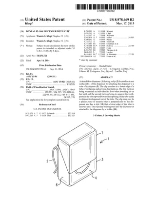
2. US. Patent Mar. 17, 2015 Sheet 1 0f3 US 8,978,669 B2
2 /3
FIG. 1
4
5 )
1 ?
( /7
2
FIG. 2 4
/
g ”’5
r V7 6
1
—_ 4-— K
2 Q | /6
6 8,9 /3
| a FIG. 3
J
3. US. Patent Mar. 17, 2015 Sheet 2 0f3 US 8,978,669 B2
> FIG. 5
5. US 8,978,669 B2
1
DENTAL FLOSS DISPENSER WITH CLIP
FIELD OF THE INVENTION
This invention relates to dental hygiene and, in particular,
to a dental ?oss dispenser with a clip that allows the dental
?oss dispenser to be attached to a tube of toothpaste or to
other articles.
BACKGROUND OF THE INVENTION
Dental ?oss is a bundle of thin ?laments used to remove
food and dental plaque from teeth. The ?oss is gently inserted
between the teeth and scraped along the teeth sides.
Dental ?oss is commonly supplied in plastic dispensers
that contain 10 to 100 meters of?oss wrapped around a spool
located within the dispenser. After pulling out the desired
amount, the ?oss is pulled against a small protected blade in
the dispenser to sever it.
Flossing in addition to tooth brushing can reduce plaque,
gingivitis andhalitosis comparedto toothbrushing alone. The
American Dental Association advises to ?oss thoroughly
once or more per day. However, even with all of the bene?ts
provided by ?ossing, many individuals forget to ?oss on a
regular basis.
Therefore, a need exists for a device to keep dental ?oss
readily available to individuals when brushing teeth so the
individuals are reminded to ?oss.
The relevant prior art includes the following references:
Pat. No. Inventor Issue/Publication Date
(U.S. Patent References)
4,788,082 Vitelle Oct. 18, 1988
5,076,302 Chari Dec. 31, 1991
5,332,107 Williams Jul. 26, 1994
5,449,092 Bazan Sep. 12, 1995
5,732,722 Mortvedt Mar. 31, 1998
6,572,063 Gitelman et al. Jun. 03, 2003
2003/0140938 Evans et al. Jul. 31,2003
7,198,051 Festa Apr. 03, 2007
8,381,743 Thomas et al. Feb. 26, 2013
D686,019 Lucsko Jul. 16,2013
(Foreign Patent References)
CN201261592 N/A Jun. 24, 2009
CN102730256 N/A Oct. 17, 2012
EP2422743 Bosch Cerda Aug. 14, 2013
SUMMARY OF THE INVENTION
The primary object ofthe present invention is to provide a
clip for storing a dental ?oss dispenser on a tube oftoothpaste
to remind individuals to ?oss every time the toothpaste is used
for brushing teeth.
An additional object of the present invention is to provide
a clip for storing a dental ?oss dispenser on a tube of tooth
paste thatprovides the convenience ofkeeping the dental ?oss
together with the toothpaste.
An additional object of the present invention is to provide
a clip for storing a dental ?oss dispenser on a tube of tooth
paste that provides the bene?t of squeezing the toothpaste
toward the opening of the tube.
The present invention ful?lls the above and other objects
by providing a dental ?oss dispenser having a clip located on
a rear surface ofthe dispenser for attaching the dispenser to a
tube oftoothpaste. The clip attaches to a lower edge of a tube
20
25
30
35
40
45
50
55
60
2
of toothpaste and serves a dual purpose. The ?rst purpose
being to remind an individual to ?oss when brushing his or
her teeth and the second purpose being to squeeze the tooth
paste in the tube upward toward the opening ofthe tube as the
toothpaste is dispensed out of the tube. The clip may also be
a planar piece of material that is perpendicular to the dis
penser and has a slot that a lower edge ofthe tube is inserted
into. The clip may be integrated into the dispenser or attached
to the dispenser by a holder that attaches to a conventional
dental ?oss dispenser.
The above and other objects, features and advantages ofthe
present invention should become even more readily apparent
to those skilled in the art upon a reading of the following
detailed description in conjunction with the drawings
wherein there is shown and described illustrative embodi
ments of the invention.
BRIEF DESCRIPTION OF THE DRAWINGS
In the following detailed description, reference will be
made to the attached drawings in which:
FIG. 1 is a front perspective view ofa dental ?oss dispenser
and clip ofthe present invention;
FIG. 2 is a side view ofa dental ?oss dispenser and clip of
the present invention;
FIG. 3 is a rear view of a dental ?oss dispenser and clip of
the present invention;
FIG. 4 is a side view ofa dental ?oss dispenser and clip of
the present invention clipped to a tube oftoothpaste;
FIG. 5 is an exploded front perspective view of a dental
?oss dispenser and holder with a clip ofthe present invention;
FIG. 6 is a front perspective view ofa dental ?oss dispenser
and holder with a clip of the present invention;
FIG. 7 is a side view of a dental ?oss dispenser and holder
with a clip of the present invention clipped to a tube of
toothpaste; and
FIG. 8 is a dental ?oss dispenser having a slotted clip ofthe
present invention.
DESCRIPTION OF THE PREFERRED
EMBODIMENTS
For purposes of describing the preferred embodiment, the
terminology used in reference to the numbered components
in the drawings is as follows:
1. dental ?oss dispenser
2. clip
3. housing of dental ?oss dispenser
4. front surface of dental ?oss dispenser
5. rear surface of dental ?oss dispenser
6. side surface of dental ?oss dispenser
7. lid of dental ?oss dispenser
8. attachment means
9. screw
. holder
. tube of toothpaste
. front panel of holder
. rear panel of holder
. side panel of holder
. opening of holder
. slotted clip
17. slot
Withreference to FIGS. 1, 2 and 3, a front perspective view,
a side view, and a rear view, respectively, of a dental ?oss
dispenser 1 and clip 2 ofthe present invention are illustrated.
The dental ?oss dispenser 1 comprises a housing 3 having a
front surface 4, rear surface 5, and side surfaces 6. Dental ?oss
6. US 8,978,669 B2
3
is stored within the housing 3 and access by opening a lid 7
hingedly attached to the housing 3. The clip 2 is attached to
the housing 3 (preferably on the rear surface 5) via an attach
ment means 8, such a screw 9, rivet, adhesive, welding, pres
sure ?tting, male/female connection, a holder 10 (as illus
trated in FIGS. 5-6) and so forth. When using a screw 9 or
other attachment means 8 that may project into the housing 3,
the screw is preferable centered over a center of a spool
located within the housing 3 so the screw 9 will not interfere
withthe rotationofthe spool when dental ?oss is being pulled
out ofthe housing 3 for use. The clip 2 may also be integral to
the dental ?oss dispenser 1.
With reference to FIG. 4, a side view of a dental ?oss
dispenser 1 and clip 2 of the present invention clipped to a
tube of toothpaste 11, is illustrated. The clip 2 is preferably
substantially U-shaped so it can be slid over the end ofa tube
of toothpaste 11 to squeeze the toothpaste in the tube 11
upward toward the opening ofthe tube 11 as the toothpaste is
dispensed out of the tube 11.
With reference to FIGS. 5 and 6, an exploded front per
spective view and a front perspective view, respectively, of a
dental ?oss dispenser 1 and holder 9 with a clip 2 of the
present invention are illustrated. The holder 9 comprises at
least one front panel 12, a rear panel 13 and side panels 14
creating an opening 15 into which the dental ?oss dispenser 2
is inserted into the holder 9. The clip 2 is attachedto the holder
9 (preferably on the rear panel 5) via an attachment means 8,
such a screw, rivet, adhesive, welding, pressure ?tting, male/
female connection, stud, slot and so forth. The clip 2 may also
be integral to the dental holder 9. The at least one front panel
12 of the holder 9 preferably has a height that is less than a
height ofthe front surface 4 ofthehousing 3, thereby allowing
the lid 7 to be opened without the any interference from the
housing 3. Likewise, the rear panel 13 ofthe holder 9 prefer
ably has a height that is less than a height ofthe rear surface
5 of the housing 3, thereby allowing the lid 7 to be opened
without the any interference from the housing 3
With reference to FIG. 7, a side view of a dental ?oss
dispenser 1 and holder 9 with a clip 2 ofthe present invention
clipped to a tube oftoothpaste 11, is illustrated. The clip 2 is
preferably substantially U-shaped so it can be slid over the
end ofa tube oftoothpaste 11 to squeeze the toothpaste in the
tube 11 upward toward the opening of the tube 11 as the
toothpaste is dispensed out of the tube 11.
Finally, with reference to FIG. 8, a dental ?oss dispenser 1
having a slotted clip 2, 16 of the present invention is illus
trated. The slotted clip 2, 16 comprises a planar piece of
material that is perpendicular to the rear surface 5 of the
dental ?oss dispenser 2 and has a slot 17 that a lower edge of
a tube oftoothpaste 11 may be inserted into. The slotted clip
2, 16 is attached to the housing 3 (preferably on the rear
surface 5) via an attachment means 8, such a screw 9, rivet,
adhesive, welding, pressure ?tting, male/female connection,
20
25
30
35
40
45
50
4
a holder 10 (as illustrated in FIGS. 5-6) and so forth. The
slotted clip 2, 16 may also be integral to the dental ?oss
dispenser 1.
It is to be understood that while a preferred embodiment of
the invention is illustrated, it is not to be limited to the speci?c
form or arrangement of parts herein described and shown. It
will be apparent to those skilled inthe art that various changes
may be made without departing from the scope ofthe inven
tion and the invention is not to be considered limited to what
is shown and described in the speci?cation and drawings.
Having thus described my invention, 1 claim:
1. A dental ?oss dispenser comprising:
an enclosed housing having a rectangular-shaped front sur
face, rectangular-shaped rear surface and rectangular
shaped side surfaces;
dental ?oss stored on a spool within said enclosed housing
and access to said dental ?oss provided by a lid that is
hingedly attached to the enclosed housing;
a clip extending from the rectangular-shaped rear surface
of the enclosed housing;
said clip having a closed end and being open on at least
three sides so said clip can be slid over a tube of tooth
paste and held in place on the tube of toothpaste via a
pressure ?t; and
said clip being in a parallel position in relation to the
rectangular-shaped rear surface ofthe enclosed housing.
2. A dental ?oss dispenser comprising:
an enclosed housing having a rectangular-shaped front sur
face, rectangular-shaped rear surface and rectangular
shaped side surfaces, thereby creating a cuboidal
shaped enclosed housing;
dental ?oss stored on a spool within said enclosed housing;
access to said dental ?oss provided by a lid that is hingedly
attached to the enclosed housing;
a clip extending from the rectangular-shaped rear surface
of the enclosed housing;
said clip having a closed end and being open on at least
three sides so said clip can be slid over a tube of tooth
paste and held in place on the tube of toothpaste via a
pressure ?t; and
said clip being in a parallel position in relation to the
rectangular-shaped rear surface ofthe enclosed housing.
3. A dental ?oss dispenser comprising:
an enclosed housing having a planar front surface, a planar
rear surface and at least one side surface;
dental ?oss stored within said enclosed housing;
a clip extending from the planar rear surface of the
enclosed housing;
said clip having a closed end and being open on at least
three sides so said clip can be slid over a tube of tooth
paste and held in place on the tube of toothpaste via a
pressure ?t; and
said clip being in a parallel position inrelationto the planar
rear surface of the enclosed housing.
* * * * *