1. * GB785473 (A)
Description: GB785473 (A) ? 1957-10-30
Improvements in implements for applying bandages to afflicted parts of the
body
Description of GB785473 (A)
COMPETE SPECIFICATION
Improvements in Implements for applying Bandages to afflicted parts of
the body
We, THE SCHOLL MANUFACTURING COM-
PANY LIMITED, a British Company, of 190
St. John Street, London, E.C.I, England, do hereby declare the
invention, for which we pray that a patent may be granted to us, and
the method by which it is to be performed, to be particularly
described in and by the following statement :
This invention relates to improvements in implements for applying
tubular bandages to parts of the human body to cover various types of
wounds, afflictions or other injuries and ailments, and to cover
similar afflictions on animals.
Implements are known for the application of tubular bandages to parts
of the body, particularly bodily appendages such as fingers, toes, and
in larger sizes to arms, legs, and even the head.
Such implements telescope over the part of the body to which the
bandage is being applied, but in use they have been found by virtue of
their construction to make contact with the portions of the body over
which they are telescoped, and while such contact may have been
strictly unintentional, nevertheless it frequently resulted in
aggravation of the particular injury or affliction being bandaged.
The main object of the present invention is to provide such implements
which during use will enable the user to avoid contact of the
implements with the injured part of the body being bandaged.
According to the invention an implement for applying tubular bandages
to part of the body comprises two elongated outwardly convex members
each having a pair of ears disposed one on each longitudinal edge at
the middle portion thereof, the adjacent ears of the two members being
2. pivotally interconnected by hinge pins passing through borings
therein, the whole presenting an outer contour free of any projection
which would hamper smooth sliding of a tubular bandage over the outer
surface of the instrument.
In a preferred construction the convex members each comprises a hollow
shell, the two shells being disposed so that the ears of one shell
overlap the ears of the other shell, the overlapping ears being
pivoted to gether by a hinge member.
The implement may have one of the ears apertured at the hinge to
provide a slipjoint connection with the hinge means whereby the space
between the shells may be varied.
By means of the invention it is more easily possible to apply a
surgical tubular bandage to the afflicted body part and tc make up a
tubular surgical bandage without touching the body part while the
implement can be adjusted to increase or decrease both the initial
spacing and the possible spread of the shells within the bandage so as
to bandage readily body parts of different sizes.
In order that the invention may be more clearly understood, a number
of constructions in accordance therewith will now be described by way
of example, with reference to the accompanying drawings, in which:
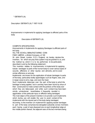
Fig. I is a side elevational view of an implement;
Fig. 2 is a plan view of a tubular bandage with which the implement
may be used:
Fig. 3 is a cross section through the bardage shown in Fig. 2:
Fig. 4 is a fragmentary elevational view showing the first step in the
application of of the bandage shown in Figs. 2 and 3 to a part of the
body employing the implement shown in Fig. 1;
Fig. 5 is a fragmentary elevational view showing a succeeding step in
the application of the bandage:
Fig. 6 is a fragmentary elevational view showing a still further step
in the application of the bandage;
Fig. 7 is an elevational view of the body
part after the application of the bandage
thereto; and
Fig. 8 is a fragmentary side perspective
view of another form of implement.
In the drawings the same numerals have
been used to indicate similar parts.
Referring to the drawings these show the
use of the implement in the application of
tubular surgical bandages to a finger, but
it will be understood that the same method,
with a larger implement, may be employed
for the application of the bandage to a foot,
3. leg, hand, arm, and even other portions of
the human body.
Referring to Fig. 1, the implement includes
a pair of elongated outwardly convex mem
bers in the form of hollow shells 1 and 2.
These shells are transversely arcuate or con
cavo-convex in shape, and the concave faces
confront each other. Intermediate the ends
thereof, the shell 1 is provided with opposed
inwardly extending ears or lugs 3 and 4,
disposed one on each longitudinal edge ,thereof and the shell 2 is
provided with a
pair of similar lugs or ears 5 and 6 disposed
one on each longitudinal edge thereof.
The ears 3 and 4 extend into over
lapping engagement with the ears 5 and 6,
and each pair of overlapping ears is hingedly
connected together as by a hinge rivet 7
extending through the overlapping portions.
The hinge rivets 7, 7 are preferably as flat
as possible on the inside so that the part
of the body over which the implement tele
scopes never comes in contact with the hinge
rivets or the respective ears which the im
plement presents an outer contour free of
any projection which would hamper free
sliding movement of a tubular bandage on
it. The ears of the two shells may however
be pivoted together in any suitable manner,
such as by nuts and bolts.
With this arrangement, it will be seen
that the implement, in effect, provides a
tubular structure with open side portions for
easy telescoping - over the part of the body
to which the bandage is to be applied. Pre
ferably, at its leading end the shell ] is pro
vided with an inward extension on opposite
sides thereof, as indicated at 8 and 9. and
the shell 2 is provided with similar inward
extensions 10 and 11. These extensions are
not arranged for overlapping relationship,
but the extensions 8 and 9 will abut the
extensions 10 and 11, respectively, if the
leading end of the implement is closed to
4. that extent. Thus, the extensions prevent
too great a closing of the implement and
also provide a more complete contact of the
implement with a tubular bandage threaded
thereover, so that the bandage substantially
n7aintains a tubular shape as a result of
spreading the shells I and 2 at the leading erd.
Obviously, in use, compression of the shells at the rear end of the
implement results in a spreading of the shells at the leadend end of
the implement, and vice l erse.
The bandage itself is shown in Figs. 2 and 3, and comprises a tubular
element 12 preferably made of a gauze-like material, inherently
stretchable and elastic to a material extent.
In the use of the invention, a section of bandage 12, substantially
twice as long as the part of the body to be covered. is taken and
threaded over the leading end of the implement as seen in Fig. 4. The
rear portions of the shells 1 and 2 are then compressed, thus
spreading the forward ends of these shells inside the bandage,
stretching the bandage proportionally. The leading end of the loaded
implement is then passed over a part of the body, such as a finger 13,
without the shells coming in contact with the finger. The end of the
bandage at the leading end of the shell is slipped off the implement,
and held in place at the rear portion of the finger, and then the
implement is withdrawn beyond the end of the finger to the position
seen in Fig. 5, and the bandage is pulled or stretched by drawing on
the implement holding the end of the bandage still loaded thereon, so
as to ensure a tight bandage around the finger The implement is then
preferably turned so as to provide a twist 14 in the bandage beyond
the end of the finger, and then the implement is slipped back over the
finger, still without contacting the finger, to substantially the
position seen in Fig. 6. This movement causes a retroverting of that
portion of the bandage still loaded on the implement, over the portion
of the bandage already applied to the finger. When the implement is
fully returned over the finger until all the bandage is stripped from
it, the implement may be removed, and the finger will be bandaged as
indicated in Fig. 7. If a full turn of the implement is made to
provide the twist 14, the end of the resultant double layer bandage
will be closed as indicated at 15 in Fig. 7.
Stretching of the bandage the first time the implement is withdrawn
from the finger is not absolutely essential since in most cases the
bandage will contract into intimate con-tact with the finger. but such
a stretching operation does ensure the bandage being tight around the
finger.
Further, if during the return movement of the partially loaded
5. implement, i.e. the retroverting operation, the implement is turned as
it is slipped over the finger a tension will be imparted to the second
layer of bandage and thus the ultimate tightness of the bandage round
the finger may be effectively governed.
Fig. 8 shows a modified construction of implement in which the spacing
between the shells 1 and 2 may be initially selected, so that the
distance between these shells may be selectively varied in order to
fit body parts of different sizes. For example, if the implement is
sized in general for application of a tubular bandage to a finger, it
is well known that with different patients the sizes of fingers vary
considerably, and so with the structure shown in Fig. 8 the shells may
be set closer together or farther apart as occasion may demand.
In the construction of Fig. 8 the shells are similar to those shown in
the construction shown in Fig. 1, with the same ears 3 and 4 on the
shell 1, and 5 and 6 on the shell 2, in overlapping relationship.
However, one of the shells, and as shown in
Fig. 8 shell 1, is provided with an opening of the general character
of a figure 8, as indicated at 16, through which the shank 17 of a
pivot rivet 7a extends. It will be noted that the shank is flattened
on opposed sides so that it is not perfectly round, but when disposed
in a certain location will pass through the neck portion of the
opening 16, so that either circular portion of that opening may be
engaged around the rivet, one rounded portion of the opening providing
a greater spread between the shells 1 and 2 than the other. The same
is true with the ears 4 and 6 on the opposite side of the structure.
Thus, with such a slip-joint pivot connection, the spacing between the
shells may be selectively varied at will.
It will be seen that the implement is very simple in construction,
highly durable, and easily manipulated, since the leading end may be
compressed while threading on the bandage, and then expanded after the
bandage has been loaded thereon, for application to the finger or
other body part. Thus, if reasonable care is utilized there is no need
for the implement intentionally or accidentally to be made to contact
the body part at any time during the application of the bandage. Also,
the implement may be readilv adjusted to accommodate body parts of
different sizes within a predetermined range, and the bandage can
slide freely over the outer contour of the implement. By the means
herein described, it is simple to apply the bandage under varying
degrees of tightness.
What we claim is:
I. An implement for use in applying tubular bandages to part of the
body comprising two elongated outwardly convex members each having a
pair of ears disposed one on each longitudinal edge at the middle
portion thereof, the adjacent ears of the two members being pivotally
6. interconnected by hinge pins passing through borings therein, the
whole presenting an outer contour free of any projection which would
hamper smooth sliding of a tubular bandage over the outer surface of
the instrument.
2. An implement according to Claim 1 wherein outwardly convex members
are in the form of transversely concavo-convex shells with their
concave surfaces facing each other.
3. An implement according to Claim 2 wherein the ears are inwardly
extending and are disposed one on each side of each shell, the two
shells being disposed so that the ears of one shell overlap the ears
of the other shell, and the overlapping ears are pivoted together by
the hinge member.
4. An implement according to Claim 2 or 3 wherein inward extensions
are provided on the sides of each shell adjacent one end of the
implement and disposed so that when that end of implement is
compressed the extensions will move into abutting relationship.
5. An implement according to any one of Claims 2 to 4 wherein the
cross-sectional area can be varied at will.
6. An implement according to Claim 3 wherein one of the ears is
apertured at the hinge to provide a slip-joint connection with the
hinge means whereby the space between the shells may be varied.
7. An implement for applying tubular surgical bandages to afflicted
body parts substantially as hereinbefore described with reference to
Figs. 1, 4, 5 and 6 or Fig. 8 of the accompanying drawings.
* GB785474 (A)
Description: GB785474 (A) ? 1957-10-30
Process for the production of polyalkylene oxide-polybasic carboxylic acid
condensation products
Description of GB785474 (A)
Translate this text into Tooltip
[75][(1)__Select language]
Translate this text into
The EPO does not accept any responsibility for the accuracy of data
7. and information originating from other authorities than the EPO; in
particular, the EPO does not guarantee that they are complete,
up-to-date or fit for specific purposes.
PATENT SPECIFICATION
Date of Application and Filing Complete Specification: Mar 21, 1 R 55.
Application mode in Germany on Mar 22, 1954.
Application made in Germany on Mar 22, 1954.
Complete Specification Published: Oct 30, i 957.
7853474 No 8090/55,.
Index at Acceptance:-Classes 1 ( 1), J 2 (A: B: C: D: E), J 3 (D: E);
2 ( 5), R 3 C( 4: 6: 9: 1 O: 16: 17, R 3 D( 2 B: 9: 12), R 27 K 2 C(
4: 6: 9: 10: 16: 17), R 27 K( 2 D: 3 MS); and 76, C 2 s(h: 3 B: 6 8).
International Classification:-01 If C 08 g C 14 c.
COMPLETE SPECIFICATION
Process for the production of Polyalkylene Oxide-polybasic Carboxylic
Acid Condensation Products.
We, BOEHME FETICHEMIE G m b HJ, a German Company, of 67,
Henkelstrasse, Duesseldorf, Germany, do hereby declare the invention,
for which we pray that a patent may be granted to us, and the method
by which it is to be performed, to be particularly described in and by
the following statement: -
This invention relates to a process for the production of condensation
products, and in particular of condensation products suitable for use
as dispersing and emulsifying agents.
It has been found that valuable condensation products are obtained
when polyalkylene oxides or their derivatives as herein defined, which
oxide or derivative possesses in addition to a lipophilic group at
least one free hydroxyl group, and has a molecular weight of at least
1000, are condensed at an elevated temperature with polybasic
carboxylic acids which contain at least three carboxyl groups and at
least one lipophilic group According to the choice 23 of starting
materials these products possess a hydrophilic or lipophilic character
and can be produced in both water-soluble and water-insoluble form
They are suitable for various technical applications, for example, for
the production of auxiliary agents for leather and textiles,
thickening agents, dispersing and emulsifying agents, lubricants,
plasticisers, synthetic materials and spongy and cellular plastics
Furthermore, they are useful for the production of surface-protection
agents, for the coating or impregnation of paper, cardboard, wood or
synthetic materials, and for the production of paste-like or solid
vehicles for colouring matters such as colour pastes, printing =
pastes and coloured leads.
-By the term " polyalkylene oxide" as used herein, we imply a compound
8. containing a plurality of alkylene oxide groups.
The term "lipophilic group" means an aliphatic, cycloaliphatic or
aliphatic-aromatic group containing at least 6 carbon atoms.
References to "high molecular weight-" compounds mean compounds
containing at least 6 carbon atoms so The polyalkylene oxides
particularly preferred are polyethylene glycols with a molecular
weight not greater than 10,000, preferably from 5000 to 10,000;
nevertheless polyethylene glycols having higher molecu-55 lar weights
are also applicable Corresponding polymerisation products of other
alkylene oxides, such as, for example, propylene oxide, and of
epichlorhydrin, can also be used, however, and, in addition, those 60
polyalkylene oxides which contain more than two terminal hydroxyl
groups and are obtainable, for example, by addition of alkylene oxides
to polyhydric alcohols such as glycerine and pentaerythritol By "
deriva 65 tives" of these polyalkylene oxides, we mean those
condensation products of alkylene oxides with high molecular weight
compounds, which contain, linked through oxygen, sulphur or nitrogen,
a lipophilic 7 group and at least one free hydroxyl group.
Such derivatives are, for example, the reaction products of higher
molecular weight alcohols, amines or mercaptans with ethylene oxide,
or the esterification products or 75 etherification products of higher
molecular weight carboxylic acids or higher molecular weight alcohols
with polyethylene oxides.
The higher molecular weight polycarboxylic acids containing at least
one lipo-80 philic group and at least three carboxyl groups in the
molecule used as starting materials can be prepared, for example, in
manner known per se by reacting unsaturated fatty acids such as oleic
acid, mixtures of 85 unsaturated fatty acids from marine animal oils,
linoleic acid, ricinoleic acid, erucic acid and brassidic acid with
maleic anhydride at temperatures above 2000 C According to the number
of double bonds and 90 t 785,474 t.ne quantity of maleic anhydride
used, triand penta-carboxylic acids and carboxylic acids of higher
basicities can thereby be obtained Instead of the unsaturated carS
boxylic acids, the corresponding unsaturated hydrocarbons can also be
employed and polycarboxylic acids are then attained which are poorer
by one carboxyl group.
The polycarboxylic acids used according to the invention, however, can
also be obtained in still other ways.
The production of the condensation products from the aforementioned
starting materials takes place by melting together the starting
substances and heating at elevated temperatures, preferably at 150-200
'C, for several hours at normal pressure or in vacuum, and removing
the water formed in the condensation During the process the usual
dehydrating condensing agents can if necessary be co-employed and in
9. certain cases also solvents and diluents can be used.
n addition, instead of the carboxylic acids, their ester-forming
derivatives such as acid halides, esters and anhydrides can be used
Pith suitable adjustment of the reaction conditions.
The relative proportions in which the starting materials are used are
variable Especially high-molecular products are obained when the molar
ratio is so chosen that all the carboxyl or hydroxyl groups present
are neutralised, such as, for examnie, the ratio 2: 3 in the case of
use of a tricarboxylic acid and a hydropolyglycol.
Furthermore, the properties of the condenNation products obtained
depend on the one hand upon the length and number of the lipophilic
groups which are in the molecule and on the other hand on the degree
of polymerisation of the polyalkylene oxide The lipophilic character
of the condensation product increases with increase of the length and
number of the lipophilic groups and the hydrophilic character
increases with increase of the degree of polymerisation of the
polyoxide It is therefore directly possible to produce water-soluble
products in this way The external character of the condensation
products obtained can also be Jetermined by the choice and relative
proportions of the components of the condensation, whereby both
viscous, paste-like products and also solid and partly elastic i 5
products can be attained which are fusible an-d capable of being
poured and can be mechanically manipulated.
The condensation products obtained are, according to their -character,
compatible With natural or synthetic oils, fats, waxes, esjn oils or
resins, natural or synthetic rubberf albumins, and also synthetic
high-polymeric compounds such as vinvl uolv mers as well as polyesters
polvarnides and the like.
652nd can be worked up jointly with these products.
EXAMPLE 1.
parts by weight of a mixture of polycarboxylic acids and their
anhydrides, prepared by heating maleic anhydride and soya 70 fatty
acid at about 220 'C, and having an acid number of 275, are heated at
180 'C.
for 8 hours in vacuum with 210 parts by weight of a polyethylene
glycol with an average molecular weight of 9000 A con 75 densate is
obtained which can be employed for the manufacture of printing pastes.
EXAMPLE 2.
9 parts by weight of a mixture of poly 80 carboxylic acids, such as
are obtained bv reaction of equimolecular amounts of linoleic acid and
maleic anhydride, are heated for 6 hours at 180-1900 C in vacuum with
187 parts by weight of a polyethylene oxide 85 of average molecular
weight 9000 A water-soluble mass is obtained which is suitable for the
manufacture of cloth finishes.
10. If instead of the polyethylene oxide of 90 molecular weight 9000, one
of average molecular weight 1500 is used, a condensate soluble with
difficulty in water is obtained which is likewise useful for cloth
finishing purposes 95 EXA Mii PLE 3.
5.7 parts by weight of a mixture of polycarboxylic acids, such as are
obtained by reaction of equimolecular amounts of oleic acid and maleic
anhydride, are heated, at 10 o 'C in vacuum for 6 hours with stirring,
with 210 parts by weight of a polyethylene oxide of average molecular
weight 9000 A condensate viscously soluble in water is obtained, which
is suitable for use as a thick o 1 s ening agent.
EXAMPLE 4.
40.4 parts by weight of thle polycarboxylic acid prepared from soya
oil fatty acid and maleic anhydride (v Example i), are ester 110 ified
with 187 parts by weight of a polyethylene oxide (molecular weight
9000) by heating in vacuum A solid condensate is obtained which is
suitable for the manufacture of coloured leads IIS Water-soluble
condensation products.
when prepared according to the present invention, make valuable
dispersing and emulsifying agents and can be used with advantage for
the production of dispersions of 120 emulsifiable or suspensible
liquid or solid substances The dispersions therewith obtained are
distinguished by being stable towards electrolytes.
These condensation products are ob 125 tained from polyalkylene oxides
of a molecular weight above 1000, particularly from 5000 to 10,000, or
from their derivatives.
which contain at least one lipophilic groun and at least one free
hydroxyl group, and 130 785,474 3 polycarboxylic acids containing at
least one fipophilic group and at least three carboxyl groups.
The dearee of solubility in water of these nroducts is determined as
stated above on he one hand by the relative proportions of ihe
starting materials which are chosen and cn the other hand by the
molecular size of he lipophilic residues present or the degree J O of
polymerisation of the polyalkylene oxide Fraction In this way
dispersing agents can be obtained which are soluble in water or
colloidally soluble in water.
As dispersible, that is emulsifiable or suspensible, liquid or solid
substances, for which the dispersing agents according to Phe invention
can be used, are first and fore-nost to be mentioned mineral, animal,
vegetable or synthetic oils, fats or waxes, which in certain cases can
also be sulphonated, also natural or synthetic resin oils or resins,
natural or synthetic rubber, albumins, synthetic high-polymeric
compounds such as polyvinyl compounds, polyesters and polyamides and
in addition inorganic or organic pigment substances such as colour
pigments, delustrants, weighting agents, filling materials, as well as
11. solid, pulverulent active materials of all kinds.
The dispersing agents are applicable, for example, in the production
of electrolytecontaining dispersions from such compounds as artificial
resins, starch, cellulose derivatives and fatty substances, for the
flameproofing or filling or weighting of textile materials, wood and
the like, in the production of tanning solutions, which besides fatty
substances have a high content of chromium and aluminium salts and/or
cornmon salt, and in the production of dispersions of pest-control
agents with inorganic salts The dispersions produced with the aid of
these substances may contain considerable amounts of inorganic or
organic, neutral, acid or to a certain extent also alkaline,
electrolytes, without fear of destruction of the dispersions during
processing or on fairly long storage, if the above-mentioned
condensation products are used as dispersing agents Other known
ionogenic or nonionogenic dispersing agents such as alkyl sulphates,
alkyl sulphonates, alkyl-benzenesulphonates, alkylphosphates, ethylene
oxide addition products of fatty acids and cation-active compounds,
can also be coemployed in the dispersions By the addition of the
dispersing agents according to the invention, the dispersions produced
with these known agents likewise become insento sitive to
electrolytes.
EXAMPLE 5.
Q( parts bv weight of sulphonated sperm el' are mixed with 5 parts by
weight of a 655 ( O ' paste of sodium alkyl sulphate (alkyl residues C
1,-C 1 j) and 5 parts by weight of a condensation product which was
obtained from 9 parts by weight of a polycarboxylic acid mixture,
obtained by reaction of linoleic acid with maleic anhydride, and 18770
parts by weight of polyethylene oxide (molecular weight 9000) by
heating for six hours at 180-190 C in vacuum An aqueous emulsion
prepared with this mixture is stable towards the addition of chrome
tanning 75 salts and common salt and can be used with advantage in a
combined oiling and tanning liquor for animal hides and skins.
EXAMPLE 6 80
In 58 parts by weight of water are dissolved 2 parts by weight of a
condensation product which was produced by esterification for 6 hours
in vacuum at 180-190 'C of a polycarboxylic acid mixture (obtained by
85 heating together maleic anhydride and soya fatty acid) with 210 5
parts by weight of polyethylene oxide (molecular weight 9000).
parts by weight of neat's foot oil are stirred into this solution,
after which the 90 mixture is emulsified in a homogenizer or in
another suitable way An emulsion stable on storage is obtained, which
is practically insensitive towards the addition of electrolytes and
can be diluted, for example, with 95 concentrated sodium chloride
solution without breaking down.
12. EXAMPLE 7.
7.5 parts by weight of a condensation 100 product, which was obtained
by esterification for 6 hours in vacuum at 180-190 'C.
of 7 6 parts by weight of a polycarboxylic acid mixture (obtained by
heating together equimolecular amounts of oleic acid and 105 maleic
anhydride) with 280 5 parts by weight of polyethylene oxide (molecular
weight 9000), are dissolved in 55 parts by weight of water 28 parts by
weight of chloro-paraffin and 2 5 Darts by weight of 110 decalin are
firstly stirred into this solution and then in addition 7 0 parts by
weight of very finely powdered chromium oxide A stable suspension is
obtained, which is suitable for the protective impregnation of tex 115
tiles.
EXAMPLE 8.
4 parts by weight of the esterification product from 7 6 parts by
weight of polycarboxylic acid (obtained from sperm oil and 120 maleic
anhydride) and 225 parts by weight of a polyethylene oxide of average
molecular weight 7500, are dissolved in 56 parts by weight of water 2
parts by weight of the addition product from 1 mole of oleyl al 125
cohol and 12 5 moles of ethylene oxide are added to this and then 38
parts by weight of sperm oil are stirred into this solution.
An extremely stable emulsion capable of being stored is obtained,
which is insensi-130 785,474 785,474 tive towards solutions of
electrolytes.
EXAMPLE 9.
7.5 parts by weight of the emulsifier emSployed in Example 7 are
dissolved in 52 5 parts by weight of water, and 40 parts by weight of
melted carnauba wax are stirred into this hot solution A viscous
emulsion, stable on storage, is obtained, which can be diluted with
hot water This emulsion can be used as a smoothing agent in the
dressing of leather.
* Sitemap
* Accessibility
* Legal notice
* Terms of use
* Last updated: 08.04.2015
* Worldwide Database
* 5.8.23.4; 93p
* GB785475 (A)
Description: GB785475 (A) ? 1957-10-30
13. Improvements in or relating to the cleaning of metal parts
Description of GB785475 (A)
PATENT SPECIFICATION
Date of Application and Filing Complete Specification: April 1, 1955.
Application made in Switzerland on April 1, 1954.
Complete Specification Published: Oct 30, 1957.
7859475 No 96 U'5155.
Index at Acceptance-Classes 32 ( 2), E 3; 91, CIA 3; and 139, Al d.
International Classification:-Cl lb C 23 g >G 04 b.
COMPLETE SPECIFICATION.
Improvements in or relating to the Cleaning of Metal Parts.
We, STARAX ETABLISSEMENT DE COMMERCE ET DE CREDIT, a body corporate
org,anised under the laws of the Principality of Liechtenstein, of
Vaduz, Principality of Liechtenstein, do hereby declare the invention,
for which we pray that a patent may be granted to us, and the method
by which it is to be performed, to be particularly described in and by
the following statement:
The present invention relates to a process and apparatus for the
cleaning of metal parts, particularly of loose material It has already
been proposed to use chemical solvents, e g trichlorethylene,
perchloroethylene etc for the removal of impurities on metal surfaces,
as e g fat and oxide-layers The effect of this degreasing method was
considerably improved by the use of supersonic waves Accordingly
soiled parts were exposed to supersonic waves, which have the effect
of detaching layers from the boundary surfaces and consequently have a
cleaning effect In the change from one particular medium to another
the sound resistances at the boundary surfaces are different and at
the resulting points of instability there arise more or less strong
amplitudes of movement, whereupon the impurities are detached from the
surface of the objects to be cleaned.
However the effect is only effective when the thickness of the object
to be cleaned amounts to not quite a quarter of the wavelength or an
uneven multiple of a quarter wavelength At those places, where the
said requirements do not apply, no cleaning can take place, because
the surface of the object is not brought into movement.
Special difficulties occur during the cleaning of loose material as e
g precision watch components The loose material is, as is known,
placed in a sieve basket and the latter dipped into a cleaning liquid,
14. to which supersonic waves are then applied The quantity of the loose
material placed in the sieve basket is limited, so that only
relatively little loose material can be cleaned at one time If the
depth of the layer of loose material exceeds a certain amount, then
the supersonic waves no longer penetrate through the layer, and all
the items of loose material 50 to be cleaned are not brought into
motion and therefore are not cleaned.
It is an object of the invention to provide an improved process and
apparatus for cleaning metal parts 55 According to the invention
therefore, we provide a process for the cleaning of metal parts, in
particular of loose material characterised in that the parts to be
cleaned are subjected to supersonic waves in a cleaning 60 liquid, and
during the treatment with super sonic waves a vacuum is produced in
the treatment chamber.
It is furthermore of advantage if the parts' to be cleaned are kept in
motion mechani 65 cally in the cleaning liquid during the supersonic
irradiation so that during the irradiation a loosening and a
re-arrangement of the parts to be cleaned takes place.
Advantageously the metal parts can be 70 set into a vibrating motion
during the super sonic irradiation Another possibility consists in
that the basket carrying the parts to be cleaned is set into rotary
movement about a horizontal axis, so that again a re-arrange 75 ment
of the metal parts takes place In this manner the metal parts are
effectively e:posed to the supersonic waves.
The apparatus suitable for carrying out the process according to the
invention corm 80 prises a vibrator, which has a sieve basket for
carrying the parts to be cleaned, which sieve basket is placed in a
container, which has a device for the production of supersonic waves
in the container and also 85 vacuum producing means for producing a
vacuum in said container.
By means of such apparatus the individual particles of loose material
not only experience a surface cleaning, but the otherwise 90 785,475
blocked up pores of the particles are comple'tely freed of fat and
other impurities.
Examination under the microscope of particles of loose material
treated in the manner described shows that the said particles have an
entirely different surface character as opposed to particles, which
have been treated in a like manner, but without a vacuum.
l It will be understood that the vacuum is adjusted to suit the vapour
pressure of the cleaning liquid, the vacuum approaching but not
actually reaching the vapour pressure of the cleaning liquid In this
way the onset of boiling of the cleaning liquid is avoided.
There will now be described by way of example only, two preferred
embodiments of the invention with reference to the accompanying
15. drawings in which:
Fig 1 is an elevation showing diagramrmatically apparatus for carrying
out the process according to the invention; and Fig 2 is an elevation
showing diagrammnatically a second embodiment of the invention.
In Fig 1 there is shown a container la.
filled with a cleaning liquid e g water or trichlorethylene, and which
has a sound head 2 a on its bottom for the production of supersonic
waves serves to receive the narticles of loose material to be cleaned.
The loose material to be cleaned is placed in a sieve basket 4 a which
is dipped in the cleaning liquid The container M a is closed in an
air-tight manner by means of a lid 7.
Furthermore a suction pipe 8 with a closure valve 10 is provided which
is connected to a high vacuum pump 9 A further pipe 11 opening into
the container l a communicates with the atmosphere and is closable by
means of a valve 12 Finally a circulating conduit 13 is connected to
the container la in which conduit 13 there is connected circulating
pump 14, and a filter 15 16 and 17 indicate valves by which the
conduit 13 can be closed.
In operation the valve 10 is opened and the valves 12, 16 and 17 are
closed There11, after the vacuum pump 9 is set in operation so that a
vacuum of between 150 mm and mm is produced in the container la At the
same time the material is subjected to the supersonic waves and
cleaning liquid.
In order always to keep the treatment liquid clean it is periodically
passed through conduit 13 in circulation and cleaned by filter 15
Finally the circulating pump 14 is switched off and the valves 16 and
17 are closed The process can also be used in conjuncGoon with a known
cleaning apparatus, in vhich the baskets are dipped in different baths
one after another by a convevor device Such an arrangement is shown in
Fi g 2.
The apparatus comprises a container 18 with a lateral opening 20
through which the containers with loose material can be loaded and
unloaded In the container 18 conveyor 70 rollers 19 are provided over
which a conveyor chain 21 runs The drive of the chains is effected in
the usual manner and is not shown in the drawings Carrier baskets 22,
which are fixed to the conveyor 75 chain by means of carrier arms 27
are provided to receive the loose material to be cleaned The lower
part of the container 18 has baths 23 in which the carrier baskets 22
are dipped one after another In each bath 80 23 a sound head 24 is
disposed for the production of supersonic vibrations Furthermore a
suction opening 25 is provided in each bath which is connected with a
vacuum pump (not shown) In order to be able to 85 produce a vacuum in
chamber 26 each arm 27 is provided with a closure lid 28 which exactly
fits the opening 29 ' of bath 23 For this purpose the opening is made
16. conical.
In order to be able to clean the treatment 90 liquid, inlet and outlet
apertures 29 and 30 are provided in each bath which, similarly to the
example according to Fig 1 are connected to a circulating pipe with a
circulating pump and filter 95 The particles of loose material treated
have an extraordinarily high degree of cleanliness and can be passed
on for further treatment, e g nickel plating, chromium plating,
without any further treatment 100
* Sitemap
* Accessibility
* Legal notice
* Terms of use
* Last updated: 08.04.2015
* Worldwide Database
* 5.8.23.4; 93p
* GB785476 (A)
Description: GB785476 (A) ? 1957-10-30
Improved casein
Description of GB785476 (A)
Translate this text into Tooltip
[75][(1)__Select language]
Translate this text into
The EPO does not accept any responsibility for the accuracy of data
and information originating from other authorities than the EPO; in
particular, the EPO does not guarantee that they are complete,
up-to-date or fit for specific purposes.
PATENT SPE Ci FIMCA Tff
Inventois:-ROBERPT DODD, ALBERT ERNEST JUDD, and GEOFFREY AUSTIN
YOUNG.
Ab, Date, of filint C'omxulete Specification 2: April 9, 1956.
Appiicatiom, Date: April 13,1955 No 10703 '55.
j, ' Comiplete Spscciflcation P 'iished: Oct 30, 1957.
17. Index at Acceptance:-Olass 2 (S), El.
International Classification: A 23 j.
COMPLETE SPECIFICATION.
Improved Casein.
We, ERIN Om LIMITED, a Company organised under the Laws of Great
Britain, of Stroud, Gloucestershire, do hereby declare the invention,
for which we pray that a patent may be granted to us, and the method
by which it is to be performed, to be particularly described in and by
the following statement: -
This invention is a process for the production of improved raw casein.
The term "raw casein" used herein means the proteins which are
obtained from animal or vegetable sources and used as raw materials
for the manufacture of casein products such as plastics and fibres and
the like.
The raw casein of animals origin, that is, obtained from mammals, is
that protein which may be precipitated from the milk of mammals, from
which the fat or cream has already been separated, by the addition of
organic or inorganic acids, by the acid produced by the activity of
miroc-organisms, by rennet, by the addition of certain organic or
inorganic water soluble salts, such as aluminium sulphate, beryllium
sulphate, cadmium acetate, calcium lactate.
zinc chloride or by any combination of these reagents.
i The raw casein of vegetable origin is, for example, the protein
obtained from the seeds of many types of plants Before precipitating
the casein the crushed seeds are first rendered free from oil, starch
and cellulosic 3.5 matter The resultant meal is then dispersed in
water and the casein precipitated by the addition of organic or
inorganic acid and/or of certain organic or inorganic water soluble
salts such as those already mentioned.
lPrice 3 s 6 d l Raw casein is a thermoplastic substance which can be
consolidated or homogenised and shaped under heat and pressure into
sheets, rods, tubes, discs, fibres and the like, after which it may be
subjected to a hardening treatment, for example, with formaldehyde,
when it loses some but not all of its thermoplastic properties Casein
products, which have been manufactured from casein which has been
produced by traditional methods, suffer from certain disadvantages,
such as some degree of opacity and a distinct yellow, orange, or even
a brown coloration.
The object of the present invention is to eliminate or reduce such
capacity and coloration This object is achieved, according to the
invention, by alternately washing the precipitated and coagulated
casein in the presence of one or more surface-active agents or wetting
agents, with water at different temperatures such that the coagulate
or curd swells during one washing and contracts during the next
18. washing The sequence of such alternate washings is desirably repeated
The surface-active agent or wetting agent is preferably introduced
prior to the precipitation and coagulation so that it is intimately
incorporated in the coagulate or curd before washing commences Thus,
as a first step, skimmed milk, which has preferably been separated at
a low temperature such as 32 ' C, or a vegetable product dispersion as
aforesaid, is treated with a surface-active agent or wetting agent or
a mixture of these agents, as a solution in water, preferably
distilled or soft water, before the addition of rennet if a rennet
type of casein is being manufactured, or before the addition of acid
or acid developing substances (serums, starters, or inoculants) if an
acid type of casein is being 785,476 gol I 785,476 produced, or before
the addition of these or any other suitable coagulant or coagulants to
the milk or vegetable product dispersion.
The surface-active agents or wetting agents, which are also sometimes
referred to as detergents or cleansing agents, the use of which we
propose in the preparation of improved raw casein, are water soluble
compounds which possess the property of combining with oils, fatty
substances, natural colouring matter and other impurities present in
the milk, vegetable product dispersion, or suspension of precipitated
casein in water; or which possess the property of forming complexes at
the interfaces between the aqueous phase and the oil, fat solid
impurity phases of the milk, vegetable dispersion or suspension of
Drecipitated casein in water; or which possess both of these
properties In the former case the surface-active agent may be said to
solubilise the impurities and in the latter case the use of the
surface-active agent leads to a reduction in the surface tension
between the various liquid and solid phases present resulting in the
emulsification of the irmpurities.
These surface-active agents exist in three classes which are known as
anion-active and non-ionic Anionic or anion-actvve surface-active
agents ionise in water solutions yielding anions and cations, and the
anion is surface-active Cationic or cationactive surface-active agents
also ionise in water solutions yielding anions and cations, and, in
this class of surface-active agents, the cation is surface-active The
non-ionic surface-active agents do not ionise in aqueous solutions, it
is also known that they form water soluble complexes with calcium and
other heavy metals in which the metal is present in an un-ionised form
All the properties possessed by the non-ionic class of surface-active
agents are particularly desirable when these agents are used for the
preparation of improved raw casein, since the use of this class of
surface-active agent does not modify the resulting casein The anionic
and cationic classes of surfaceactive agents may be used effectively
for the preparation of improved raw casein, but the time of
19. precipitation of the casein is influenced by the agent used and, since
casein forms complexes with anions and with cations, the use of these
two classes of agents is li Uely to be less efficient than the use of
the non-ionic class owing to the absorption of the anions or cations
by the casein and, in addition, the properties of di O the improved
raw casein may be modified.
Although it is desirable that non-ionic surface-active or wetting
agents should be used for the preparation of improved raw casein,
anionic and cationic surface-active f 35 or wetting agents may be
used.
The process of casein coagulation is allowed to proceed by the
addition of the precipitating or coagulating agent or agents needed to
produce the desired raw casein, having first brought the milk or
vegetable 70 product dispersion to a suitable temperature for this
coagulation Whereas this coagulation temperature is not critical for
our purpose and, for the production of a rennet type casein may be
between 200 and 50 C 75 we prefer a temperature between 30 ' and 320 C
and for an acid type of casein the temperature may be between 370 and
C the actual temperature depending on the particular type of acid
casein being So produced and the condition of the skim milk or the
type of vegetable product dispersion used Our process is not confined
to these temperature ranges.
When preparing improved raw casein from 85 milk it is an advantage to
dilute the milk with water before the addition of the surfaceactive or
wetting agent or agents The addition of water to the extent of 10 %NO
by volume of the milk has been found to be 90 effective but the actual
volume of water added may vary from 0 to 25 %' of the volume of milk
used.
In the preferred process, after coagulation of the casein from the
milk or dispersion, 95 the curd is heated with the whey at a rate of
increase of temperature not exceeding 1 C per minute, sufficiently for
it to be handled but not to such a temperature that the curd becomes
ubbery or St ingy il Ioo texture or coagulates into large masses It is
very desirable that at no early stage in the preparation and washing
of the casein, is the milk, dispersion, curd or whey heated above 60 '
C On reaching the maximum O os temperature desired the curd is
separated from the whey as rapidly as possible by any convenient
method The curd is then washed with clean water at 40 ' to 60 ' C.
with efficient agitation for about 10 minutes 110 and is then
preferably separated from the wash water A second washing of the curd
with water at a temperature below 20 " C.
is carried out with agitation for at least 15 minutes A third wash is
carried out 115 similarly to the first, and a fourth similarly to the
second.
20. Casein curd swells in cold water and contracts when immersed in hot
water, thus by washing the curd with alternate cold and; 120 hot
washing water the curd is caused to swell and contract thus absorbing
clean water and expelling water loaded with impurities The impurities
are given up to the washing water the more readily and, in _'25 fact,
mainly due to the solubilisin and emulsifying or stabilising action of
the surface-active agent.
It is not essential that the first wash after the separation of the
whey should be hot, 120 water separated in a centrifuge The curd in
the centrifuge basket was soaked in water at 15 C for 20 minutes and
then centrifuged dry Further 20 minute soakings followed by
centrifuging were carried out at 600 C and 15 ' C using fresh water
each time After the final (cold) wash and centrifuging the curd was
ground and dried in a current of air preheated to 450 C.
The product was used for the manufacture of sheets by the extrusion of
rods followed by pressing in the manner well known to those skilled in
the art When these sheets had been formalised, dried and polished it
was observed that they were practically colourless and possessed a
high clarity The term "formalised" used throughout the Specification,
refers to a process which consists of the treatment of the sheets by
immersion in aqueous formaldehyde solutions, usually referred to as
formalin solutions This treatment results in the production of a
tough, substantially water resistant, casein-formaldehyde plastic
material.
it may be a cold wash-although we prefer a hot wash-but in this case
where the first wash is cold, the next wash should be hot and the
final wash should be cold although, provided that the curd has four
washings, a final warm wash at a temperature preferably not exceeding
450 may be used The separation of whey or washing water from the curd
may be achieved with advantage by means of a centrifuge.
For the highest clarity and least colour in the product it is
preferable that the water used for washing should be soft and that it
should be changed for each washing period.
The surface-active agent or agents may be applied to the coagulated
casein in the washing water instead of being applied to the skim milk
or vegetable product dispersion Casein having improved clarity and
colour is Droduced in this manner, although we prefer the addition of
the surface-active agent or agents to be made to the milk or vegetable
product dispersion before coagulation.
After washing at least four times, as described above, and preferably
six times, the curd is de-watered by pressing in a suitable press or
by means of a centrifuge It may :Su then be ground to a suitable
granule size in a curd mill and dried in a current of air to a
temperature not exceeding 50 C and a relative humidity of 40 to 50 %
21. Alternatively, the casein curd may, with advantage, be dried under
reduced air pressure and with lower temperatures.
In order to facilitate a better under.
standing of the invention and of how it may be carried into effect,
the following Examples are given by way of illustration: EXAMPLE 1.
19 gallons of skimmed milk were brought to a temperature of 310 C and
190 ml of an aqueous solution of an alkylated phenol ethylene oxide
condensate, previously mixed into 1 litre of distilled water, added
with stirring This was followed by the addition of 38 ml rennet mixed
into 200 ml.
5,0 distilled water After these ingredients had been well mixed the
milk was allowed to stand at 310 C until coagulation took place
minutes after the addition of the rennet solution The curd was broken
and the curds and whey stirred whilst heating the whole to 490 C
during a period of 18 minutes, and then the whey was decanted from the
curd Water at 60 C was poured into the curd and the curd washed in
this water with continuous agitation for 2 C minutes The water was
then run off and replaced with water at 150 C and the curd again
washed with agitation for 20 minutes The curd was then washed with
water al 60 C for 20 minutes and the curd and so EXAMPLE 2.
19 gallons of separated milk were stirred and maintained at 31 C
whilst adding 95 grams of an anhydrous condensation product of a
lon,-chain fatty alcohol and ethylene 95 oxide which possesses a
polyethylene glycol chain, -reviously dispersed and dissolved in 500
ml distilled water, and 15 ml rennet mixed into 100 ml distilled water
As soon as the ingredients had been well mixed the 100 agitation was
stopped until the casein was coagulated in 24 minutes, at which moment
agitation was re-started and the curds and whey steadily heated to 49
C in 20 minutes The whey was drained off from 105 the curd, and
replaced by clean water at 57 ' C and the curd washed with agitation
for 20 minutes This water was poured off and replaced with water at 15
C and the curd washed again with agitation for 20 110 minutes Two
further washings, the first at 60 C and the last at 150 C were carried
out with agitation and each being for 20 minutes The casein curd was
Dressed for hour, ground and dried in a current of air 115 preheated
at 450 C.
This casein was mixed with water and manufactured into sheets in the
manner well known to those skilled in the art These sheets were
formalised and dried in the 120 usual manner When polished these
sheets were observed to be clear and almost colourless.
EXAMPLE 3.
6 gallons of separated milk were heated 125 to 38 ' C and 30 grams of
the anhydrous condensation product referred to in Example 2 dispersed
and dissolved in 100 ml distilled water, were added and mixed into the
22. milk The milk was then inoculated with 130 785,476 j lactic starter
and allowed to coagulate by the natural development of acidity without
stirring When coagulated the curds and whey were heated to 43 ^ C at a
rate of increase of temperature not exceeding 15 C per minute, and the
whey poured off Water at 50 ' C.
was poured on to the curd to wash it for 20 minutes with agitation
After pouring off this water three further washings were carried out
at 15 ' C, 50 ' C and 15 ' C.
each being for 20 minutes with agitation.
This curd was then pressed, ground and dried in a current of air at 45
^ C.
This casein after moistening with water was extruded into rods and
pressed into sheets in the manner well known to those skilled in the
art After formalisation and drying the polished sheets were seen to be
transparent and to have only a slight colour.
EXAMPLE 4.
gallons of skimmed milk were heated to 31 ' C and 1 gallon of
distilled water at 31 C was added and stirred in 100 grams of the
anhydrous condensation product referred to in Example 2, dissolved in
1 litre of distilled water was added to the diluted milk and well
stirred 10 ml rennet mixed into 200 ml distilled water was then
stirred into the milk and the casein allowed to coagulate while
stirring The casein coagulated in 17 minutes and the curd was heated
with the whey to 60 ' C during 30 minutes The whey was drained from
the curd and replaced with clean water at 38 ' C.
and the curd washed with agitation for 15 minutes This water was
poured off and replaced with water at 15 ' C and the curd washed for
15 minutes before draining the water off Four further washings, at 60
' C.
at 15 ' C, at 60 ' C and, finally at 15 ' C.
were carried out in the same manner The casein curd was pressed for 15
minutes, ground in a curd mill and dried in a current of air preheated
at 450 C.
This casein was used for plastic manufacture in the same manner as
described in Examples 1 and 2 The casein-forinaldehyde sheets produced
from this batch of casein were clear and practically colourless.
Casein produced according to any of the foregoing Examples is useful
for producing fibres capable, in the form of yarns and fabrics, of
being dyed to any desired colour.
* Sitemap
* Accessibility
* Legal notice
* Terms of use
23. * Last updated: 08.04.2015
* Worldwide Database
* 5.8.23.4; 93p
* GB785477 (A)
Description: GB785477 (A) ? 1957-10-30
An improved joint for use in erecting tubular framework
Description of GB785477 (A)
PATENT SPECIFICATION
7,059477 Date of Application and filing Cornplete Specification April
14, ( 955 No 10744 '55.
Application made in Italy on May It, 1954.
Comnplete Specification Published: Oct 30, 1957.
Index at Accaptan:e:-(Classes 2 ( 2)) S 3; and 44, BE(SA: 6 D 1).
Internationa 2 Classification:-F 04 g FO 6 b.
COMPLETE SPECIFICATION
An improved Joint for use in Eredtiig Tubular Framework.
We, FERROTUBI S p A, an Italian body ferred to as a continuous
element) at an corporate, of 4 Via Lanzone, Milan, Italy, intermediate
point of the same, that is, withdo hereby declare the invention, for
which out interrupting the continuity of the said we pray that a
patent mnay be granted to tubular element inside of the joint, as was
us and the method by which it is to be per the case with the common
joints of the type 50 formed, to be particularly described in and
first described.
by the following statement: Particularly, the joint, according to the
Various and numerous forms of joints for invention is characterised in
that it cornconnecting the tubes of tubular framework prises elements
provided with curved seats Ware known, for facilitating, for example,
the for a continuous tubular element, besides 55 quick and demountable
construction of scaf expandable wings for connection of the foldings,
shelvings and the like Many types joint to the ends of one or more
other tubuof joints are also known for connecting lar elements to be
connected with the first tubular elements and amongst them are tube so
that the axes of these various elesome in which the connection between
24. the ments intersect each other at a common / joint and each tubular
element is obtained point, the expansion, of the wing elements by
sliding the ends of each tubular element of the joint being effected
by mean t over projections belonging to the separate or more screws
adapted -pr"sainst the parts of the joint, and which, after the in otr
wall-tl Cuous tubular element troduction of thetubeared-t a-irm ve
disposed in the hollow seats of the various 65 apart from each other
in such a way as to elements constituting the joint.
exert a great pressure upon the walls of the The joint according to
the invention is also tube, thus ensuring a rigid connection be
suitable for conmecting lattice work or tween joint and tube framework
and particularly for thb mountOther types of joints are, instead, pro
ing of tubes intended to serve as stays N vided with parts arranged to
encircle the the latter case it comprises two part collar tubular
elements to which they are con or part-circle shaped parts engaiiin
each nected -by pressure upon the outside of the other in a plant
parallel to the axis of the wall of the tube The latter type of joint
main tube encircled by the c 6 llar, wherein is commonly applied at
intermediate points the two parts of the collar have extensions 75 of
the tubular elements and therefore the which, when brought together,
form a forcaxes of the tubular elements connected by ing plug for
insertion in the end of tfie tubuthe said joints lie in different
planes and lar stay to be connected Two set screws therefore do not
intersect each other Joints penetrating radially through the collar
down R of the first mentioned type instead, connect to the main tube
are arranged to force the 80 to each other tubular elements in such a
two halves of the plug apart reciprocally.
manner that the axes of the latter intersect thus causing it to
operate as an expander, at a single point, but they are commonly so as
to lock the collar to the tubular stay applied to the extremities of
the tubes as well as to the main tube and consequently The joint that
is the object of the present stabilise the junction between the two
tubes 85 invention is a combination of the two above Some forms of the
invention are illustrated types of joints and can therefore be defined
in the accompanying drawings in which:
as a joint of the first mentioned type pro Fig 1 is a side view of the
elements.
vided, however, with parts capable of en separated from each other, of
a joint aocircling a tubular element (hereinafter re cording to the
invention, and suitable for 90 (Price 3/6) tioc l _ 785,477 ccmnecting
a continuous tubular element, wvith two more tubes at right angles to
each other as well as to the continuous tube.
Fig 2 shows the same joint assembled and connecting the three tubes
above referred to.
25. Fig 3 shows an assembled ioint according to the invention adapted to
connect to each other a continuous tubular element and 10three
elements engageable by their ends.
Fig 4 is an analogous view to the preceding ones, of a joint adapted
to interconnect five tubular elements of which one is continuous, and
the other four are disposed two by two aligned one aligned pair being
at right angles to the other aligned pair and both pairs at right
angles to the first cited continuous element.
Fig 5 is a perspective view of the Fig 4 foint with portions of the
elements connected by it.
Fig 6 is a side view of a joint for assembling tubes intended to serve
as stays.
Fig 7 is a view of the rear end in the direction of the arrow 60 of
Fig 6, which 2 S directed along the axis of the tubular stay to be
connected and shown in chain lines.
Fig 8 is a view of the front end in the direction of the arrow 51 of
Fig 6 also directed along the axis of the tubular stay.
According to Figs I and 2, the joint according to the invention
comprises in its simplest form an element 1 having a semicircular seat
adapted partly to encircle the is continuous tubular element over
which the ntl is to be applied: the said element 1, extending around
three quarters of a circle.
ends at its extremities with two wings 2 and 3 respectively, having a
T-shaped cross section and adapted to be inserted together with
corresponding wings presented by the element 4 of the same joint into
the extremities of the other two tubular elements that the joint is to
connect These wings are indicated by 5 and 6 in Figs 1 and 2, the
element 4 being such as partially to encircle the portion of the
continuous tubular element, that is indicated in Fig 2 by 10, of which
one half only is engaged by the S Oelement 1 The joint is completed by
a screw threaded element or set screw 7 which co-operates with a
corresponding tapped hole provided in the element 4 and whose axis is
oblique with respect to the axes of 55the tubular elements 11 and 12
and therefore of the pairs of wings 2-5 and 3-6.
The assembled joint is clearly illustrated 2 N Fig 2, from which it
can be seen how the continuous element 10 is connected with the other
tubular elements 11 and 12 engaged with the joint by their extremities
The mounting of the above described joint -is very simple and -is as
follows: the element 1, of the joint having been placed around the
tube 10, the element 4 will be put in place and then over the pair of
wings 2-5 and 3-6 will be slid the ends of the tubes 11 and 12
respectively This done, the screw threaded element 7 is screwed into
the corresponding hole 7 ' and tightened by 70 means of a suitable key
thus Dressing against the outer wall surface of the tube 10 and
26. forcing the element 4 and conseouentlv the wings 5 and 6 carried by
the latter, to move away from the element 1 and its respective 75
wings 2 and 3, so as to cause a strong pressure to be exerted upon the
inner wall surfaces of the tubes 11 and 12 respectively.
said pressure being sufficient for rigidly connecting the said joint
and the tubular ele 80 ments 11 and 12 as well as the element 10 which
will be gripped between the inner end of the set screw 7 and the seat
provided for it upon the part 1.
To take these elements apart it will be 85 sufficient to loosen the
set screw 7 and all the elements of the joint will move apart
permitting an easy separation of the tubular elements 10, 11, 12.
The joint illustrated by Fig 3 is analogous 90 to the preceding one,
only it is suitable for connecting an additional member besides those
already considered, i e the continuous tubular element 10 ' with three
tubular elements 11 ', 12 ' and 13 ' connected to the 95 joint by
their ends.
The joint of Fig 3 comprises an element 14 shaped to fit against one
half of the tube ' and ending at its extremities, respectively by the
wings 15 and 16 aligned with 100 each other The joint is completed by
the elements 18 and 19 each provided with a pair of wings 20 and 21,
22 and 23 respectively, at right angles to each other and capable of
coupling to each other in the 105 manner clearly shown in the drawing
after their engagement with the ends of the aforesaid tubular elements
I ', 12 ', 13 '.
The expansion of this joint, intended to guarantee the rigid
connection of the various 110 tubular elements by means of the joint,
is effected by tightening down hard the two screws 17 and 17 ' in a
similar manner to the screw 7 described with reference to Figs.
1 and 2 115 The joint shown in Figs 4 and 5 can interconnect one more
tubular element as compared with Fig 3 It is composed of four elements
30, 31, 32 and 33 equal to each other and equal to the elements 18 and
120 19 of Fig 3 Each of them is provided with two wings 34 and 35, 36
and 37 38 and 39, and 41 respectively, which, when the joint is in the
assembling position, will lie adjacent in pairs as clearly illustrated
in Fig 125 4 and upon each of these pairs of wings there will be slid
an end of each of the elements 24, 25, 26 and 27 These tubular
elements will thus be rigidly connected to each other as well as to
the continuous tubular elerment 130 785,477 28 passing through the
joint just described.
The joint will be put under tension by tightening the screws 42, 43,
44 and 45 and by so doing there will be obtained a rigid connection
between the 5 elements 28, 27, 26, and 24, the first one being a
continuous element projecting from both sides of the joint.
The joint could also comprise but two lodiagonally placed set screws
27. as for instance 42 and 44, in place of four, as in the drawing.
The structures obtainable with this type of joint possess the
advantage of having the indifferent elements connected with axes
converging to a point, and besides, as they permit of one amongst the
connected elements being continuous, have the advantage of possessing
a greater strength especially for shelving and for the laying of
floors or the like.
Lastly the other characteristic of the improved joint is the provision
of T-shaped wines in place of tubular connectors, thus 2 obtaining,
for the same weight, the advantage of a greater strength of the joint.
The joint represented in Figs 6, 7 and 8 is particularly suitable for
the mounting of cross and other stav members intended to impart
rigidity to the structure.
This joint is divided into two semi-circular parts 52 and 52 ', each
of which is formed with at least one projecting tooth 53 and at least
one depression 53 ' reciprocally engaging with the corresponding
depression and tooth of the other half-ring in a direction parallel to
the osculating plane of the other two ends 54, 54 ' Each of these end
portions 54, 54 ' terminates with a T-shaped piece 55, 55 ' forming
when together a crossshaped plug which enters the tube 56 and can be
fixed through two set screws 57, 57 ' which by pressing on to the tube
58, lock the tube 56 upon the plug 55-55 ', whose halves are forced
apart from one another or expanded against the inside of tube 56, in
this way the two tubes 56 and 58 are firmly secured together.
The shape of the elements constituting the halves of the plug 55-55 '
may be that represented in Fig 8, or any other suitable shape just as
their length may vary, according to the strength desired, but the
profiles of the interengaging teeth and depressions should s be shaped
to form a perfectly fitting coupling conforming to the contour of the
adjacent parts of the collar.
It is understood that the materials constituting the different
elements of the joint, 6 O the dimensions and constructional details
may be varied according to necessity, without departing from the field
of the present invention as defined by the appended claims.
* Sitemap
* Accessibility
* Legal notice
* Terms of use
* Last updated: 08.04.2015
* Worldwide Database
* 5.8.23.4; 93p