
Recommended
Recommended
More Related Content
Similar to John deere power tech e 2.4l diesel engines service repair technical manual (ctm101019)
Similar to John deere power tech e 2.4l diesel engines service repair technical manual (ctm101019) (20)
More from ufjjsjekkeemme
More from ufjjsjekkeemme (20)
Recently uploaded
Recently uploaded (20)
John deere power tech e 2.4l diesel engines service repair technical manual (ctm101019)
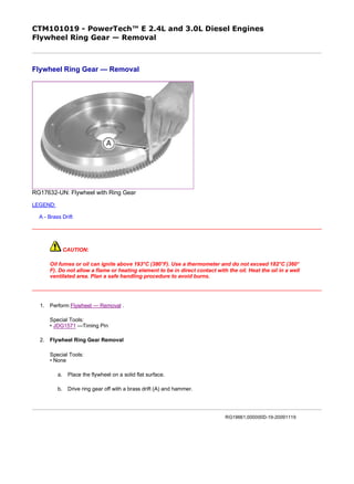
- 1. CTM101019 - PowerTech™ E 2.4L and 3.0L Diesel Engines Flywheel Ring Gear — Removal Flywheel Ring Gear — Removal RG17632-UN: Flywheel with Ring Gear LEGEND: A - Brass Drift CAUTION: Oil fumes or oil can ignite above 193°C (380°F). Use a thermometer and do not exceed 182°C (360° F). Do not allow a flame or heating element to be in direct contact with the oil. Heat the oil in a well ventilated area. Plan a safe handling procedure to avoid burns. 1. Perform Flywheel — Removal . Special Tools: • JDG1571 —Timing Pin 2. Flywheel Ring Gear Removal Special Tools: • None a. Place the flywheel on a solid flat surface. b. Drive ring gear off with a brass drift (A) and hammer. RG19661,000000D-19-20091119 1/1 2019/11/27file:///C:/ProgramData/Service%20ADVISOR/Temp/CTM101019_09001faa8...
- 2. CTM101019 - PowerTech™ E 2.4L and 3.0L Diesel Engines Flywheel Ring Gear — Installation Flywheel Ring Gear — Installation 1. Flywheel Ring Gear Installation Special Tools: • None Consumables: • None IMPORTANT: If flame heat is used, be sure gear is heated uniformly around circumference. DO NOT OVERHEAT. SEE CAUTION. Overheating may also destroy original heat treatment of gear. a. Heat new ring gear to 148°C (300°F) using either heated oil, oven heat, or flame heat. b. Install ring gear against shoulder of flywheel. 2. Perform Flywheel — Installation . Special Tools: • JDG1571 —Timing Pin Consumables: • LOCTITE ® 242 Thread Lock and Sealer (Medium Strength), Flywheel Cap Screws LOCTITE is a trademark of Loctite Corp. MK41968,000001E-19-20090915 1/1 2019/11/27file:///C:/ProgramData/Service%20ADVISOR/Temp/CTM101019_09001faa8...
- 3. CTM101019 - PowerTech™ E 2.4L and 3.0L Diesel Engines Flywheel Housing — Removal Flywheel Housing — Removal RG17652-UN: Flywheel Housing LEGEND: A - Cap Screws 1. Perform Flywheel — Removal . Special Tools: • JDG1571 —Timing Pin 2. Flywheel Housing Removal Special Tools: • None a. Remove starting motor if desired. Starting motor and flywheel housing may be removed as an assembly. b. CAUTION: The flywheel housing is heavy. Plan a proper handling procedure to avoid injuries. Remove flywheel housing-to-cylinder block cap screws (A). Remove flywheel housing from block. RG19661,0000013-19-20090917 1/1 2019/11/27file:///C:/ProgramData/Service%20ADVISOR/Temp/CTM101019_09001faa8...
- 4. CTM101019 - PowerTech™ E 2.4L and 3.0L Diesel Engines Flywheel Housing — Installation Flywheel Housing — Installation RG17652-UN: Flywheel Housing LEGEND: A - Cap Screws 1. Flywheel Housing Installation Special Tools: • None Consumables: • None a. Inspect and clean cylinder block and flywheel housing and mating surfaces. b. CAUTION: The flywheel housing is heavy. Plan a proper handling procedure to avoid injuries. Install flywheel housing on cylinder block and tighten cap screws (A) to specifications. NOTE: Some flywheel housings may use a sheet metal plate as part of the enclosure, install as necessary. 2. Perform Flywheel — Installation . Special Tools: • JDG1571 —Timing Pin Consumables: • LOCTITE ® 242 Thread Lock and Sealant (Medium Strength) Item Measurement Specification Initial Flywheel Housing Cap Screws Torque 35 N•m (26 lb-ft) Final Flywheel Housing Cap Screws Torque 140 N•m (105 lb-ft) LOCTITE is a trademark of Loctite Corp. RG19661,000001F-19-20100601 1/1 2019/11/27file:///C:/ProgramData/Service%20ADVISOR/Temp/CTM101019_09001faa8...
- 5. CTM101019 - PowerTech™ E 2.4L and 3.0L Diesel Engines Flywheel — Installation Flywheel — Installation Special Tools: • JDG1571 —Timing Pin Consumables: • LOCTITE ® 242 Thread Lock and Sealer (Medium Strength), Flywheel Cap Screws 1. CAUTION: Flywheel is heavy. Plan a proper handling procedure to avoid injuries. IMPORTANT: Flywheel MUST BE clean and free of any oil, grease or debris. RG17650-UN: Flywheel and Guide Studs LEGEND: A - Guide Studs Install two guide studs (A) in crankshaft cap screw threaded holes. Place flywheel on studs and slide into position against crankshaft. 2. IMPORTANT: ALWAYS use new flywheel cap screws when flywheel has been removed. Inspect cap screws to insure they have sealant. If required, apply LOCTITE® 242 Thread Lock and Sealer (Medium Strength) to cap screws threads. Start cap screws in crankshaft. Do not tighten until guide studs are removed and all cap screws are started. Insert JDG1571 timing pin to prevent crankshaft rotation. Tighten cap screws in a cross-shaped sequence to specifications. Item Measurement Specification Initial Flywheel Mounting Cap Screws Torque 30 N•m (20 lb-ft) 1/2 2019/11/27file:///C:/ProgramData/Service%20ADVISOR/Temp/CTM101019_09001faa8...
- 6. Final Flywheel Mounting Cap Screws Torque 110 N•m (80 lb-ft) LOCTITE is a trademark of Loctite Corp. RG19661,000000E-19-20090915 2/2 2019/11/27file:///C:/ProgramData/Service%20ADVISOR/Temp/CTM101019_09001faa8...
- 7. CTM101019 - PowerTech™ E 2.4L and 3.0L Diesel Engines Assembled ID of Main Bearing Caps — Measurement Assembled ID of Main Bearing Caps — Measurement RG7537-UN: Measuring Assembled Main Bearing Cap ID RG7405-UN: Cylinder Block to Crankshaft Centerline LEGEND: A - Top Deck-to-Centerline Bearing Bore 1. Remove bearing inserts from caps and cylinder block. Keep inserts in correct order if they are to be reused. 2. Clean and inspect caps for damage. Small burrs or nicks on flat surfaces may be removed with a file. Use a medium- grit polishing cloth to dress curved bearing surfaces. 3. Install bearing caps (without bearings) in cylinder block. Tighten cap screws to specifications. Item Measurement Specification 1/2 2019/11/27file:///C:/ProgramData/Service%20ADVISOR/Temp/CTM101019_09001faa8...
- 8. 4. Measure ID of bearing cap bores. 5. If bearing caps are damaged or bore is not within specification, replace cylinder block. Main Bearing Cap Screws Torque 80 N˙m (59 lb-ft) Item Measurement Specification Crankshaft Main Bearing Bore (Without Bearings) ID 79.892—79.918 mm (3.1454—3.1464 in.) Crankshaft Main Bearing Bore Centerline-to-Top Deck Distance 274.960—275.040 mm (10.8252—10.8283 in.) RG19661,000001C-19-20070109 2/2 2019/11/27file:///C:/ProgramData/Service%20ADVISOR/Temp/CTM101019_09001faa8...
- 9. CTM101019 - PowerTech™ E 2.4L and 3.0L Diesel Engines Essential, Recommended and Fabricated Tools For This Group Essential, Recommended and Fabricated Tools For This Group NOTE: Order tools according to information given in the U.S. SERVICEGARD ™ Catalog or from the European Microfiche Tool Catalog (MTC). • JDG1691 —Balancer Shaft Bushing Service Set • JDG1571 —Timing Pin • JDG1694 —Camshaft Bushing Service Set • JDG1678 —Hydraulic Lifter Bleeddown Tool SERVICEGARD is a trademark of Deere & Company MK41968,000000D-19-20090717 1/1 2019/11/27file:///C:/ProgramData/Service%20ADVISOR/Temp/CTM101019_09001faa8...
- 10. CTM101019 - PowerTech™ E 2.4L and 3.0L Diesel Engines Balancer Shafts — Removal (If Equipped) Balancer Shafts — Removal (If Equipped) RG13037-UN: Balancer Weights Removal RG13039-UN: Balancer Shaft Removal 1. Drain engine oil and engine coolant. 2. Perform Fan Assembly — Removal . Special Tools: • None 3. Perform Fan and Alternator Belt — Removal . Special Tools: • None 4. Perform Fan Pulley — Removal . Special Tools: • None 5. Perform fan bearing removal. See: 1/3 2019/11/27file:///C:/ProgramData/Service%20ADVISOR/Temp/CTM101019_09001faa8...
- 11. Thank you very much for your reading. Please Click Here. Then Get COMPLETE MANUAL. NO WAITING NOTE: If there is no response to click on the link above, please download the PDF document first and then click on it.
- 12. Fan Bearing (Standard-Duty) — Removal . Special Tools: • JDG1679 —Fan Bearing Remover & Installer Kit • JDG10409 —Wrench Adapter or Fan Bearing (Heavy-Duty) — Removal . Special Tools: • JDG10409 —Wrench Adapter 6. Remove the idler pulley below the alternator. See: Idler Pulley(s) with Lift Strap — Removal . Special Tools: • None 7. Perform Automatic (Spring) Belt Tensioner — Removal . Special Tools: • None 8. Perform Coolant Pump — Removal . Special Tools: • None 9. Perform Crankshaft Pulley/Damper — Removal . Special Tools: • JDG1571 —Timing Pin 10. Perform Oil Pan — Removal . Special Tools: • None 11. Perform Oil Pick-up Tube Assembly — Removal . Special Tools: • None 12. Perform Timing Gear Cover — Removal . Special Tools: • None 13. Balancer Shafts Removal Special Tools: • None a. Rotate crankshaft until balancer weight cap screws point straight down into the oil pan. b. Remove weights from balancer shafts. IMPORTANT: Identify left and right balancer shafts for correct assembly. Permanently mark a letter “R” or letter “L” on the thrust plate for identification. 2/3 2019/11/27file:///C:/ProgramData/Service%20ADVISOR/Temp/CTM101019_09001faa8...
- 13. c. Remove two cap screws from balancer shaft thrust plate. NOTE: When removing balancer shafts, use caution to insure shaft journals and bushings are not damaged. d. Carefully remove balancer shafts. MK41968,0000300-19-20100414 3/3 2019/11/27file:///C:/ProgramData/Service%20ADVISOR/Temp/CTM101019_09001faa8...
- 14. CTM101019 - PowerTech™ E 2.4L and 3.0L Diesel Engines Balancer Shaft Bushings and Journals — Inspection and Measurement Balancer Shaft Bushings and Journals — Inspection and Measurement Special Tools: • None Consumables: • None RG17353-UN: Balancer Shaft Bushing Bores Measurement RG17354-UN: Balancer Shaft Journal OD Measurement LEGEND: A - Bushing ID B - Journal OD 1. Inspect, measure and record bushing ID (A) at all locations. 2. Measure balancer shaft journal OD (B). Difference between journal OD and bushing ID is oil clearance. If oil clearance is not within specification, install new bushings and, if necessary, new balancer shaft. Item Measurement Specification Balancer Shaft Bushing (New) ID 30.038—30.104 mm (1.1826—1.1852 in.) 1/2 2019/11/27file:///C:/ProgramData/Service%20ADVISOR/Temp/CTM101019_09001faa8...