
Recommended
Recommended
More Related Content
Similar to John deere 450 clc excavator service repair technical manual (tm1925)
Similar to John deere 450 clc excavator service repair technical manual (tm1925) (13)
More from ufjkskefmsmerty
More from ufjkskefmsmerty (20)
Recently uploaded
Recently uploaded (20)
John deere 450 clc excavator service repair technical manual (tm1925)
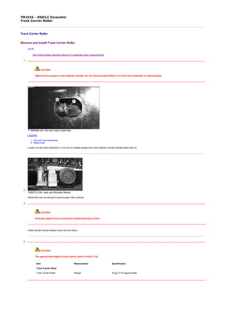
- 1. TM1925 - 450CLC Excavator Track Carrier Roller Track Carrier Roller Remove and Install Track Carrier Roller NOTE: See Undercarriage Appraisal Manual for component wear measurements. 1. CAUTION: High pressure grease in track adjuster cylinder. Do not remove grease fitting or nut and valve assembly to release grease. T138569B-UN: Nut and Valve Assembly LEGEND: 1 - Nut and Valve Assembly 2 - Bleed Hole Loosen nut and valve assembly (1) one turn to release grease from track adjuster cylinder through bleed hole (2). 2. T6557DJ-UN: Jack and Wooden Blocks Raise track link just enough to permit upper roller removal. 3. CAUTION: Securely support track to prevent accidental lowering of track. Install wooden blocks between track link and frame. 4. CAUTION: The approximate weight of track carrier roller is 35 kg (77 lb). Item Measurement Specification Track Carrier Roller Track Carrier Roller Weight 35 kg (77 lb) approximate 1/3 2020/2/17file:///C:/ProgramData/Service%20ADVISOR/Temp/TM1925_09001faa80209...
- 2. T7029AL-UN: Cap Screw and Roller LEGEND: A - Upper Roller B - Cap Screw (4 used) Remove cap screws (B) to remove upper roller (A). 5. Install upper roller (A). Tighten cap screws (B). 6. Check roller oil level by removing plug in cover. Add oil as necessary. (See Track Roller, Front Idler, and Carrier Roller Oil in Operator's Manual.) Approximate oil capacity is 120 mL (4 fl oz). 7. Remove wooden blocks and jack. 8. Check and Adjust Track Sag . (See Operator's Manual.) Disassemble and Assemble Track Carrier Roller T8267AC-UN: Track Carrier Roller Assembly LEGEND: A - Cap Screw (3 used) B - Plug C - Cover D - O-Ring E - Thrust Washer F - Bushing G - Bushing H - Roller I - Cap Screw (3 used) J - Metal Face Seal K - Axle L - Bracket M - Cap Screw (4 used) 1. Remove plug (B) to drain oil. 2. Remove parts (A, C—E and I) to remove roller (H). Item Measurement Specification Track Carrier Roller Roller-to-Frame Cap Screw Torque 393 N˙m (290 lb-ft) 2/3 2020/2/17file:///C:/ProgramData/Service%20ADVISOR/Temp/TM1925_09001faa80209...
- 3. 3. IMPORTANT: Metal face seals can be reused if they are not worn or damaged. A seal must be kept together as a set because of wear patterns on seal ring face. Remove metal face seal (J) from roller (H) and bracket (L). Keep seal rings together as a matched set with faces together to protect lapped surfaces. Inspect metal face seals . (See procedure in this group.) 4. Remove bushings (F and G) if replacement is necessary. 5. Replace parts as necessary. 6. Install bushing (F) in roller so flange is tight against shoulder. Install bushing (G). 7. IMPORTANT: O-rings and seat surfaces must be clean, dry, and oil free so O-rings do not slip when roller is turning. Thoroughly clean the O-rings and seat surfaces in roller, bracket, and seal rings using a volatile, non-petroleum base solvent and lint-free tissues. 8. Install O-ring on seal rings. 9. Install seal rings and O-rings as an assembly into bracket (L) and roller (H). Apply equal pressure with the fingers at four equally spaced points on seal ring face. Seal must “pop” into place so O-ring and seal ring is seated squarely in bore. 10. NOTE: A volatile, non-petroleum base solvent or talcum power may be used as a lubricant. Clean seal ring face using clean oil and lint-free tissues. Apply a thin film of oil to each seal ring face. 11. Install roller (H) and thrust washer (E). Tighten cap screws (I). 12. Install O-ring (D) and cover (C). Tighten cap screws (A). 13. Fill roller with 120 mL (4 fl oz) of clean oil. See Track Roller, Front Idler, and Carrier Roller Oil. (See Operator's Manual.) 14. Apply cure primer and pipe sealant to threads of plug (B). Install plug. Item Measurement Specification Track Carrier Roller Thrust Washer-to-Axle Cap Screw Torque 64 N˙m (47 lb-ft) Item Measurement Specification Track Carrier Roller Cover-to-Roller Cap Screw Torque 64 N˙m (47 lb-ft) LOCTITE is a trademark of Loctite Corp. OUOE003,00000A3-19-20010308 3/3 2020/2/17file:///C:/ProgramData/Service%20ADVISOR/Temp/TM1925_09001faa80209...
- 4. TM1925 - 450CLC Excavator Remove and Install Track Shoe Remove and Install Track Shoe T6557DO-UN: Track Shoe Cap Screws T6794AM-UN: Track Shoe Nuts T6352AH-UN: Tightening Sequence 1/2 2020/2/17file:///C:/ProgramData/Service%20ADVISOR/Temp/TM1925_09001faa80209...
- 5. LEGEND: A - Rounded Edge B - Chamfered Edge 1. Remove nuts, cap screws, and shoe. 2. Apply a light coat of oil to cap screw threads and install shoe. 3. Install all track shoe nuts with rounded edges (A) against the link and chamfered edges (B) away from the link. Be sure nut is properly positioned in the link so there is full contact between the nut and the link. 4. Starting at any cap screw, tighten cap screws in sequence shown. Item Measurement Specification Track Shoe Shoe-to-Chain Cap Screw Torque 1375 N˙m (1015 lb-ft) TX,0130,DV2791-19-19940609 2/2 2020/2/17file:///C:/ProgramData/Service%20ADVISOR/Temp/TM1925_09001faa80209...
- 6. TM1925 - 450CLC Excavator Track Chain Track Chain Remove Track Chain 1. CAUTION: High pressure grease in track adjuster cylinder. Do not remove grease fitting or nut and valve assembly to release grease. T138569B-UN: Nut and Valve Assembly LEGEND: 1 - Nut and Valve Assembly 2 - Bleed Hole Loosen nut and valve assembly (1) one turn to release grease from track adjuster cylinder through bleed hole (2). 2. T7029AN-UN: Cap Screw and Roller LEGEND: A - Master Pin B - Cotter Pin Move track chain so master pin (A) is over front idler. 3. Remove cotter pin (B). 4. Remove nuts and cap screws to remove shoe on each side of master pin. 5. Put a wooden block in front of idler and under chain so chain does not fall when master pin is removed. 6. Raise excavator just enough so bottom of sprocket clears track chain. 1/5 2020/2/17file:///C:/ProgramData/Service%20ADVISOR/Temp/TM1925_09001faa80209...
- 7. 7. T7029AP-UN: Master Pin Removal Using Track Press LEGEND: A - Master Pin Remove master pin (A) using 100 ton track press. 8. Pry apart chain and lower end of track. 9. Slowly turn sprocket in reverse direction to remove track chain from excavator. 10. Remove collars from master link counterbores. 11. Inspect parts and repair as necessary. Install Track Chain 1. Install track chain so section on ground has pin boss on links towards rear of unit. 2. Install end of chain on sprocket and slowly turn sprocket in forward direction to pull chain across top of frame to front idler. 3. T7029AQ-UN: Master Pin Installed LEGEND: A - Collars B - Master Pin C - Cotter Pin Install collars (A) in counterbores. 4. Pull ends of chain together. 5. Install master pin (B) using 100 ton track press. 6. Install cotter pin (C). 7. Lower excavator. 8. Apply a light coat of oil to threads of cap screws. 9. Install shoe on each side of master pin. 2/5 2020/2/17file:///C:/ProgramData/Service%20ADVISOR/Temp/TM1925_09001faa80209...
- 8. 10. T6557DO-UN: Track Shoe Cap Screws T6794AM-UN: Track Shoe Nuts T6352AH-UN: Tightening Sequence LEGEND: A - Rounded Edge B - Chamfered Edge Install all track shoe nuts with rounded edges (A) against the link and chamfered edges (B) away from the link. Be sure nut is properly positioned in the link so there is full contact between the nut and the link. 11. Starting at any cap screw, tighten cap screws in sequence shown. Disassemble and Assemble Track Chain Item Measurement Specification Track Chain Shoe-to-Chain Cap Screw Torque 1375 N˙m (1015 lb-ft) 3/5 2020/2/17file:///C:/ProgramData/Service%20ADVISOR/Temp/TM1925_09001faa80209...
- 9. T7029AG-UN: Track Chain Assembly LEGEND: A - Left Master Track Link B - Right Master Track Link C - Master Bushing D - Collar (2 used) E - Right Track Link (52 used) F - Seal (104 used) G - Bushing (52 used) H - Left Track Link (52 used) I - Shoe (53 used) J - Pin (52 used) K - Cotter Pin L - Master Pin 1. Remove parts (A—L). Inspect and replace parts as necessary. 2. Install parts. Item Measurement Specification Track Chain Master Pin OD 47.30 mm (1.86 in.) new 44.30 mm (1.74 in.) minimum used Master Bushing ID 47.90 mm (1.89 in.) new 50.90 mm (2.00 in.) minimum used Track Pin OD 47.57 mm (1.87 in.) new 44.57 mm (1.75 in.) minimum used 4/5 2020/2/17file:///C:/ProgramData/Service%20ADVISOR/Temp/TM1925_09001faa80209...
- 10. Minimum used is the maximum allowable wear for turning pins and bushings. Measure bushing outer diameter at the two worn places using a caliper such as the D17524C1 100 mm Caliper from JT05518A or JT05523 Undercarriage Inspection Service Tool Kit. NOTE: See Undercarriage Appraisal Manual SP326 for additional information. Bushing ID 48.40 mm (1.91 in.) new 49.43 mm (1.95 in.) minimum used OUOE003,00000A4-19-20010309 5/5 2020/2/17file:///C:/ProgramData/Service%20ADVISOR/Temp/TM1925_09001faa80209...
- 11. Thank you very much for your reading. Please Click Here. Then Get COMPLETE MANUAL. NO WAITING NOTE: If there is no response to click on the link above, please download the PDF document first and then click on it.
- 12. TM1925 - 450CLC Excavator Remove and Install Sprocket Remove and Install Sprocket IMPORTANT: Sprocket must be replaced when the tooth tips become excessively rounded, worn, or chipped to prevent excessive wear to chain. If machine is driven in one direction a majority of the time, wear will be on one side of teeth. To extend service life, change sprockets from one side of machine to the other. 1. Disconnect Track Chain from sprocket. (See procedure in this group.) 2. Lift side of machine so sprocket teeth clear chain. 3. CAUTION: The approximate weight of sprocket is 85 kg (187 lb). Remove sprocket cap screws. 4. Attach sprocket to hoist, remove and move to other side of machine or replace. 5. Install sprocket. Apply thread lock and sealer (high strength) to threads of cap screws and tighten. 6. Check and Adjust Track Sag . (See Operator's Manual.) Item Measurement Specification Sprocket Sprocket Weight 85 kg (187 lb) approximate Item Measurement Specification Sprocket Sprocket-to-Gearbox Cap Screw Torque 740 N˙m (545 lb-ft) LOCTITE is a trademark of Loctite Corp. OUOE003,00000A5-19-20010309 1/1 2020/2/17file:///C:/ProgramData/Service%20ADVISOR/Temp/TM1925_09001faa80209...
- 13. TM1925 - 450CLC Excavator Front Idler Front Idler Remove and Install Front Idler NOTE: See Undercarriage Appraisal Manual for component wear measurements. T7029BB-UN: Front Idler LEGEND: A - Front Idler 1. Disconnect Track Chain . (See procedure in this group.) 2. Slide front idler (A) forward using a pry bar. 3. CAUTION: The approximate weight of front idler is 275 kg (606 lb). Attach front idler to hoist and remove from frame. 4. Replace parts as necessary. 5. Install front idler and slide rearward into frame as far as possible. 6. Connect Track Chain . (See procedure in this group.) Disassemble Front Idler Item Measurement Specification Front Idler Front Idler Weight 275 kg (606 lb) approximate 1/6 2020/2/17file:///C:/ProgramData/Service%20ADVISOR/Temp/TM1925_09001faa80209...
- 14. T8267AD-UN: Front Idler Assembly LEGEND: A - Pin (2 used) B - Bushing (2 used) C - Idler D - Plug (2 used) E - Bracket (2 used) F - Metal Face Seal (2 used) G - Guard H - Cap Screw (3 used) I - Lock Washer (3 used) J - Yoke K - Cap Screw (4 used) L - Lock Washer (4 used) M - O-Ring (2 used) N - Axle 1. Remove cap screws (H). Remove guard (G). 2. Remove cap screws (K). Remove yoke (J). 3. Remove plug (D) to drain oil. Approximate capacity is 450 mL (15 fl oz). 4. IMPORTANT: Metal face seals can be reused if they are not worn or damaged. A used seal must be kept together as a set because of wear patterns on seal ring face. 2/6 2020/2/17file:///C:/ProgramData/Service%20ADVISOR/Temp/TM1925_09001faa80209...