Copper Tube Crimping Lugs Guide
•
1 like•2,170 views

Cembre Cable Lugs LV - Cembre A Copper Cable Lugs

Recommended
Recommended
More Related Content
What's hot
What's hot (20)
Similar to Copper Tube Crimping Lugs Guide
Similar to Copper Tube Crimping Lugs Guide (20)
More from Thorne & Derrick International
More from Thorne & Derrick International (20)
Recently uploaded
Recently uploaded (20)
Copper Tube Crimping Lugs Guide
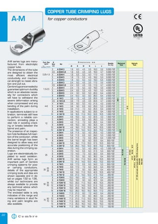
- 1. COPPER TUBE CRIMPING LUGS A-M 22 35 50 50 50 70 70 16,0 16,0 17,0 18,0 19,0 17,0 17,0 18,0 19,0 20,0 26,0 20,5 20,5 21,5 25,0 25,5 29,5 33,5 22,5 26,0 26,5 30,5 34,5 39,5 25,5 29,0 29,5 33,5 37,5 42,5 28,0 31,5 32,0 36,0 40,0 45,0 34,0 34,5 38,5 42,5 47,5 40,5 42,5 46,5 51,5 55,5 59,5 44,0 46,0 50,0 55,0 59,0 63,0 3,2 3,7 4,3 5,3 6,4 3,2 3,7 4,3 5,3 6,4 8,4 3,2 3,7 4,3 5,3 6,4 8,4 10,5 4,3 5,3 6,4 8,4 10,5 13,2 4,3 5,3 6,4 8,4 10,5 13,2 4,3 5,3 6,4 8,4 10,5 13,2 5,3 6,4 8,4 10,5 13,2 6,4 8,4 10,5 13,2 15,0 17,0 6,4 8,4 10,5 13,2 15,0 17,0 5.000/100 5.000/100 5.000/100 5.000/100 5.000/100 4.000/100 4.000/100 4.000/100 4.000/100 4.000/100 2.500/100 2.000/100 2.000/100 2.000/100 2.000/100 2.000/100 1.500/100 1.000/100 1.500/100 1.500/100 1.500/100 1.000/100 1.000/100 1.000/100 1.000/100 1.000/100 1.000/100 500/100 500/100 500/100 1.000/100 500/100 500/100 500/100 500/100 500/100 500/100 500/100 400/100 400/100 300/50 200/50 200/50 200/50 200/50 200/50 200/50 200/50 200/50 200/50 150/50 100/50 100/50 RHU 520 3,5 3,5 4,0 4,5 5,0 3,5 3,5 4,0 4,5 5,0 8,0 3,5 3,5 4,0 6,0 6,0 8,0 10,0 4,0 6,0 6,0 8,0 10,0 12,0 4,0 6,0 6,0 8,0 10,0 12,0 4,0 6,0 6,0 8,0 10,0 12,0 6,0 6,0 8,0 10,0 12,0 7,0 8,0 10,0 12,0 14,0 16,0 7,0 8,0 10,0 12,0 14,0 16,0 ECW-H3D 4,5 4,5 5,0 5,5 6,0 4,5 4,5 5,0 5,5 6,0 9,0 4,5 4,5 5,0 6,5 7,0 9,0 11,0 5,0 6,5 7,0 9,0 11,0 14,0 5,0 6,5 7,0 9,0 11,0 14,0 5,0 6,5 7,0 9,0 11,0 14,0 6,5 7,0 9,0 11,0 14,0 8,0 9,0 11,0 14,0 16,0 18,0 8,0 9,0 11,0 14,0 16,0 18,0 Hydraulic Tools B 51 6,0 6,5 6,5 7,5 9,0 6,0 6,5 7,5 8,5 9,0 12,0 7,5 7,5 8,0 9,0 11,0 14,0 16,5 10,0 10,0 11,0 15,0 18,0 19,0 11,5 11,5 11,5 15,0 18,0 20,0 14,0 14,0 14,0 15,0 18,0 21,0 17,0 17,0 17,0 19,0 21,0 19,0 19,0 20,0 21,0 25,0 26,0 21,0 21,0 21,0 22,0 25,0 26,0 Mechanical Tools RH 50 1,8 1,8 1,8 1,8 1,8 2,4 2,4 2,4 2,4 2,4 2,4 3,6 3,6 3,6 3,6 3,6 3,6 3,6 4,6 4,6 4,6 4,6 4,6 4,6 5,8 5,8 5,8 5,8 5,8 5,8 7,0 7,0 7,0 7,0 7,0 7,0 8,9 8,9 8,9 8,9 8,9 10,0 10,0 10,0 10,0 10,0 10,0 11,3 11,3 11,3 11,3 11,3 11,3 Box/Bag B 15 d HT 120 and tools and heads with 130 kN crimping force 25 35 35 L HT 51 25 N RHU 81 16 Quantity M HT 81-U 10 mm B HT 45-E 4÷6 A 03-M 3 A 03-M 3,5 A 03-M 4 A 03-M 5 A 03-M 6 A 06-M 3 A 06-M 3,5 A 06-M 4 A 06-M 5 A 06-M 6 A 06-M 8 A 1-M 3 A 1-M 3,5 A 1-M 4 A 1-M 5 A 1-M 6 A 1-M 8 A 1-M 10 A 2-M 4 A 2-M 5 A 2-M 6 A 2-M 8 A 2-M 10 A 2-M 12 A 3-M 4 A 3-M 5 A 3-M 6 A 3-M 8 A 3-M 10 A 3-M 12 A 5-M 4 A 5-M 5 A 5-M 6 A 5-M 8 A 5-M 10 A 5-M 12 A 7-M 5 A 7-M 6 A 7-M 8 A 7-M 10 A 7-M 12 A 10-M 6 A 10-M 8 A 10-M 10 A 10-M 12 A 10-M 14 A 10-M 16 A 14-M 6 A 14-M 8 A 14-M 10 A 14-M 12 A 14-M 14 A 14-M 16 Dimensions Øi TN 70 SE 1,5÷2,5 3 3,5 4 5 6 3 3,5 4 5 6 8 3 3,5 4 5 6 8 10 4 5 6 8 10 12 4 5 6 8 10 12 4 5 6 8 10 12 5 6 8 10 12 6 8 10 12 14 16 6 8 10 12 14 16 Ref. TN 120 SE 0,25÷1,5 Ø Stud mm HN 1 Cond. Size sqmm low stranded flexible* HN 5 A-M series lugs are manufactured from electrolytic copper tube. The dimensions of the tube are designed to obtain the most efficient electrical conductivity and mechanical strength to resist vibration and pull out. Cembre lugs are annealed to guarantee optimum ductility which is an absolute necessity for connectors which will have to withstand the severe deformation arising when compressed and any bending of the palm during installation. In applications subject to vibration, terminals still have to perform a reliable connection, annealing plays a vital role in avoiding cracking or breaks between the barrel and palm. The presence of an inspection hole facilitates full insertion of the conductor, whilst the barrel length has been designed to allow easy and accurate positioning of the dies during the crimping operation. Lugs are electrolytically tinplated to avoid oxidation. A-M series lugs form an important part of Cembre crimping systems for power carrying conductors, details of the appropriate crimping tools and dies are shown opposite and in detail on pages 132 to 136, whilst our technicians are always available to provide any technical advice which may be required. The enclosed table is only indicative of the range and many variations in stud fixing and palm lengths are also available. for copper conductors
- 2. COPPER TUBE CRIMPING LUGS A-M for copper conductors 185 240 240 300 240 400 300 500 400 630 500 800 630 1000 800 7,0 8,0 10,0 12,0 14,0 16,0 20,0 8,0 10,0 12,0 14,0 16,0 20,0 11,0 11,0 14,0 16,0 17,0 20,0 11,0 11,0 14,0 16,0 17,0 20,0 11,0 11,0 14,0 16,0 17,0 20,0 11,0 14,0 16,0 19,0 23,0 19,0 19,0 19,0 23,0 19,0 23,0 19,0 23,0 19,0 23,0 19,0 23,0 50,5 52,5 56,5 61,5 65,5 69,5 77,5 54,0 58,0 63,0 67,0 71,0 79,0 69,0 69,0 75,0 79,0 81,0 87,0 76,0 76,0 82,0 86,0 88,0 94,0 82,0 82,0 88,0 92,0 94,0 100,0 96,0 99,0 103,0 106,0 112,0 113,0 113,0 113,0 119,0 117,0 123,0 128,0 134,0 141,0 145,0 158,0 162,0 6,4 8,4 10,5 13,2 15,0 17,0 21,0 8,4 10,5 13,2 15,0 17,0 21,0 8,4 10,5 13,2 15,0 17,0 21,0 8,4 10,5 13,2 15,0 17,0 21,0 8,4 10,5 13,2 15,0 17,0 21,0 10,5 13,2 15,0 17,0 21,0 13,2 15,0 17,0 21,0 17,0 21,0 17,0 21,0 17,0 21,0 17,0 21,0 Box/Bag Mechanical Tools 100/25 100/25 100/25 100/25 100/25 100/25 100/25 100/25 100/25 100/25 50/25 50/25 50/25 50/25 50/25 50/25 50/25 50/25 50/25 50/25 50/25 50/25 50/25 30/15 30/15 30/15 30/15 30/15 30/15 30/15 30/15 20/10 20/10 20/10 20/10 20/10 15/5 20/5 20/5 20/5 15/5 15/5 12/6 15/5 9/3 9/3 6/2 6/2 Hydraulic Tools ECW-H3D 8,0 9,0 11,0 14,0 16,0 18,0 22,0 9,0 11,0 14,0 16,0 18,0 22,0 13,0 13,0 16,0 18,0 19,0 22,0 13,0 13,0 16,0 18,0 19,0 22,0 13,0 13,0 16,0 18,0 19,0 22,0 20,0 20,0 22,0 22,0 24,0 22,0 22,0 22,0 24,0 22,0 24,0 22,0 24,0 24,0 24,0 24,0 24,0 d RHU 520 25,0 25,0 25,0 25,0 25,0 27,0 29,5 28,5 28,5 28,5 28,5 28,5 30,0 31,5 31,5 31,5 31,5 31,5 31,5 35,5 35,5 35,5 35,5 35,5 35,5 39,0 39,0 39,0 39,0 39,0 39,0 44,0 44,0 44,0 44,0 44,0 51,0 51,0 51,0 51,0 56,5 56,5 61,6 61,6 72,0 72,0 80,0 80,0 Quantity L B 51 13,5 13,5 13,5 13,5 13,5 13,5 13,5 15,2 15,2 15,2 15,2 15,2 15,2 16,7 16,7 16,7 16,7 16,7 16,7 19,2 19,2 19,2 19,2 19,2 19,2 21,1 21,1 21,1 21,1 21,1 21,1 23,7 23,7 23,7 23,7 23,7 27,0 27,0 27,0 27,0 30,3 30,3 33,4 33,4 38,0 38,0 44,0 44,0 mm RHU 81 N HT 120 and tools and heads with 130 kN crimping force 150 185 185 M RH 50 120 150 150 B HT 81-U 95 120 120 A 19-M 6 A 19-M 8 A 19-M 10 A 19-M 12 A 19-M 14 A 19-M 16 A 19-M 20 A 24-M 8 A 24-M 10 A 24-M 12 A 24-M 14 A 24-M 16 A 24-M 20 A 30-M 8 A 30-M 10 A 30-M 12 A 30-M 14 A 30-M 16 A 30-M 20 A 37-M 8 A 37-M 10 A 37-M 12 A 37-M 14 A 37-M 16 A 37-M 20 A 48-M 8 A 48-M 10 A 48-M 12 A 48-M 14 A 48-M 16 A 48-M 20 A 60-M 10 A 60-M 12 A 60-M 14 A 60-M 16 A 60-M 20 A 80-M 12 A 80-M 14 A 80-M 16 A 80-M 20 A 100-M 16 A 100-M 20 A 120-M 16 A 120-M 20 A 160-M 16 A 160-M 20 A 200-M 16 A 200-M 20 Dimensions Øi HT 51 70 95 6 8 10 12 14 16 20 8 10 12 14 16 20 8 10 12 14 16 20 8 10 12 14 16 20 8 10 12 14 16 20 10 12 14 16 20 12 14 16 20 16 20 16 20 16 20 16 20 Ref. TN 120 SE 95 Ø Stud mm HT 45-E Cond. Size sqmm low stranded flexible* *Actual conductor section may require a larger lug eg for 120mm2 size use A30-... lug. 23
- 3. 30 4,3 5,5 7,0 8,0 14,5 18,0 20,3 24,5 35,1 41,1 45,0 55,0 500/100 500/100 300/100 200/50 HNN 3 HNN 4 Hydraulic Tools ECW-H3D 8,0 9,2 11,1 13,6 Mechanical Tools Box/Bag L HT 120 and tools and heads with 130 kN crimping force Quantity P TNN 70 ANE 2-P 12 ANE 3-P 14 ANE 5-P 16 ANE 7-P 20 mm B TNN 120 HT 51 RH 50 B 51 10 16 25 35 Dimensions Ø UNINSULATED PIN CONNECTORS Quantity Øi B P L 4,8 5,9 7,0 8,9 10,0 11,5 4,3 5,5 7,0 8,0 9,5 11,0 14,5 18,0 20,3 24,5 26,0 31,0 23,5 28,0 32,0 39,0 45,0 55,0 Box/Bag 1.500/100 1.500/100 1.000/100 500/100 250/50 200/50 Mechanical Tools HN 1 Hydraulic Tools ECW-H3D mm HT 120 and tools and heads with 130 kN crimping force A 2-P 12 A 3-P 14 A 5-P 16 A 7-P 20 A 10-P 25 A 14-P 30 Dimensions HT 45-E 10 16 25 35 50 70 Ref. HT 51 RH 50 B 51 Conductor Size sqmm B 15 A-P series pin connectors are designed to terminate conductors into contact blocks. They are manufactured from copper strip, rolled, brazed and tin plated. Ref. TN 120 SE A-P Conductor Size Flexible sqmm HN 5 ANE-P series terminals are made from electrolytic copper, rolled, tin plated and brazed. The interior of the Nylon insulation sleeve is funnel shaped so as to ensure complete and easy introduction of the conductor strands. In order to achieve the best electrical and mechanical performance it is suggested that they are crimped using dies and tools specifically developed for this purpose by Cembre. TN 70 SE ANE-P NYLON INSULATED PIN TERMINALS