1. 140 141TELE-audiovision International — The World‘s Largest Digital TV Trade Magazine — 03-04/2013 — www.TELE-audiovision.com www.TELE-audiovision.com — 03-04/2013 — TELE-audiovision International — 全球发行量最大的数字电视杂志
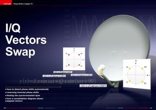
I/Q
Vectors
Swap
• how to detect phase shifts automatically
• reversing inverted phase shifts
• finding the synchronization byte
• how a constellation diagram shows
swapped vectors
FEATURE Phase Shifts in Digital TV
2. ■graph 1.
■graph 3.
■graph 2.
142 TELE-audiovision International — The World‘s Largest Digital TV Trade Magazine — 03-04/2013 — www.TELE-audiovision.com
FEATURE Phase Shifts in Digital TV
Jacek
As satellite signal analyzers become more and more
affordable, many satellite enthusiasts decide to buy
and use them. When they start playing with their new
instruments, they sometimes encounter terms not so
obvious to everybody. Transponder frequency, symbol
rate, FEC or polarization are commonly used and most
of the users have no problem in apprehending their
meaning. But I/Q vectors can be a puzzle for some of
the fans. You can see “I/Q Normal” and “I/Q Inverted”
(or “I/Q Swapped”) options in some analyzer screens.
What does it mean? In fact, it is not anything complex
and we will explain it in a simple way in this feature
article.
Phase
shift
Symbol
45° 00
135° 01
225° 11
315° 10
Let’s consider the simplest
form of modulation used in
satellite TV – QPSK. In this
modulation, the sinusoidal
signal amplitude remains
unchanged but its phase can
change at regular intervals.
For example, if we have a
transponder broadcasting
with a symbol rate of 27.5
Ms/sec, its phase can change
27.5 million times in a sec-
ond. Or we can say that one
symbol lasts for
sec (about 36 nanoseconds).
There are four phase shifts
allowed in QPSK what cor-
responds to four different
symbols.
In the figures below
(graph.1-3), you can see an
example of a QPSK modulat-
ed carrier with all four possi-
ble phase shifts in the order:
45°, 135°, 225°, 315°.
In this example, there are
3. ■graph 4. ■graph 5.
144 TELE-audiovision International — The World‘s Largest Digital TV Trade Magazine — 03-04/2013 — www.TELE-audiovision.com
four symbols sent: 00, 01, 11
and 10. Just to remind you,
in QPSK, a symbol is a pair
of subsequent bits.
Phase shifts are produced
by summing a carrier sig-
nal with the auxiliary signal
of the same frequency but
shifted in phase by 90°. A
QPSK modulated signal can
be defined as:
The resulting y(t) is also a
sine function but its ampli-
tude and phase depends on
the I and Q values. In QPSK
modulation I and Q can be
equal either to 1 or to -1.
Therefore we have four dif-
ferent possibilities for y(t):
or
or
or
A pair of bits is assigned
to each possible state of
y(t) in QPSK. This is shown
graphically in a constella-
tion. (graph 4.)
In other words, if the in-
coming signal is shifted 45°
in phase,
,
your receiver understands
that two zero bits are be-
ing sent to it. If the signal is
shifted by 135°, your box as-
sumes that bits 1 and 0 have
arrived and so on.
And what will happen if we
swap the I and Q vectors?
This may happen if some-
body unintentionally sets
up the headend in a wrong
way or simply will not take
into account the natural vec-
tor swap that takes place
in some frequency conver-
sions.
In such situation the con-
stellation will look differently
– see the graph 5.
The 45° and 225° shifts
produce the same bits as
previously but the remain-
ing two: 135° and 315° are
swapped.
So, in a continuous flow of
bits, some pairs of bits will
stay undistorted (00 and
11) but the other pairs will
take reverse values 10 will
change to 01 and vice versa.
That’s the effect of inverted
I/Q modulation.
Some old timers can still
remember the first genera-
tion of satellite receivers that
in their transponder data re-
quired the user to define I/Q
Normal or I/Q Inverted. More
recent receiver can auto-
matically detect I/Q inversion
and reverse the operation of
their demodulators accord-
ingly. But how is it possible to
detect a I/Q swap?
The transport stream con-
sists of fixed length data
packets. For example the
DVB standard requires the
packet to have 204 bytes.
The very first byte in every
packet is always the same
0x47 in hexadecimal nota-
tion or simply 01000111 in
binary format. It is called
the sync byte as it is used
for synchronization. Your re-
ceiver right after tuning to a
new transponder starts look-
ing for the 0x47 bytes to find
the ones located every 204
bytes in a stream. Only in
this way it can start decod-
ing the content of the pack-
ets. If it is impossible to find
regularly spaced 0x47 bytes,
it is a clear indication that
I/Q vectors are swapped. So,
the receiver also swaps I/Q
signals in its demodulator
because one inversion and
another inversion recreates
the normally modulated sig-
nal again.
The principle described
above applies also to more
complex modulations like
8PSK or QAM. The only dif-
ference is that I and Q can
take more values than 1
and -1 as in QPSK what re-
sults in more phase shifts
and amplitude values of y(t).
The effect of I/Q swap is
the same: some bits remain
unchanged, the others are
reversed (0 becomes 1 and
vice versa). However, as you
already know now, it is not
so difficult to detect such
situation and take counter-
measures - simply apply
additional I/Q swaps in a re-
ceiver.
Signal analyzer can detect
I/Q swap on the same basis
as your receiver does. QPSK
modulators usually offer in
their menu a possibility to
invert I and Q vectors. To-
day, it does not make any
difference to your receiv-
er whether a transponder
transmits with normal or in-
verted I/Q vectors. And the
viewer cannot sense it in any
way either.